Article
Printed in Brazil - ©2015 Sociedade Brasileira de Química0103 - 5053 $6.00+0.00
A
*e-mail: [email protected]
Theoretical Study of Molecular and Electronic Structures of 5
1Knot Systems:
Two-Layered ONIOM Calculations
Aguinaldo R. de Souzaa and Nelson H. Morgon*,b
aDepartamento de Química, Faculdade de Ciências de Bauru, Universidade Estadual Paulista, 17030-360 Bauru-SP, Brazil
bInstituto de Química, Universidade Estadual de Campinas, 13083-970 Campinas-SP, Brazil
In this study we examine the electronic and molecular structures of the [51 knot···(PF6)10]+
pentafoil knot system and report calculated interaction energies that result from halides (X = F, Cl, Br, and I) localized at the center of the [51 knot···(PF6)9]X molecular structure. The equilibrium
geometries were fully optimized at the ONIOM(M06/6-31G(2d,p):PM6) level of theory, starting from an initial geometry for the pentafoil knot obtained from experimental X-ray data. The molecular systems were divided into two layers, for which the M06/6-31G(2d,p) level of theory was used to describe the high layer ([C4H6]5X– structure) and the PM6 semiempirical method was
employed for the low layer. The calculated electronic energies show that the interaction between the fluorine anion and the pentafoil knot produces the most stable structure, whereas an unfavorable interaction is observed for iodide due to the diffuse character of its electronic cloud. Using basis set superposition error (BSSE) correction techniques, the observed values of the interaction are –0.201 hartrees for the fluoride ion and –0.100 hartrees for iodide.
Keywords: electronic and molecular structures, pentafoil knot, ONIOM
Introduction
Knot theory has been developed by mathematicians and physicists since the 18th century and although knotted
chemical structures remain bizarre for chemists, several knots are already well-known and characterized. Knotted structures occur in nature as knotted proteins,1-3 DNA,4 and
organic molecules.5 Knots, links, graphs, and various other
topological isomers have been discussed in monographs on chemical conformation and chirality.6
A knot is a closed, one dimensional, and non-intersecting curve in three dimensional space. From a more mathematical and set-theoretic point of view, a knot is a homeomorphism (an additive and continuous function) that maps a circle into three dimensional space and cannot be reduced to the unknot (a circle).7
In mathematical language, a knot is the embedding of a circle in three-dimensional Euclidean space, 3.7 In 1860,
Lord Kelvin stated that atoms could be represented by knots in the aether, which led Peter Tait to create the first knot table classification. The study of knots is a central subject
in mathematics, particularly in the area of topology and has recently attracted the attention of the chemistry and physics communities, whose goal is to obtain molecules and new materials with such topology. Consequently, knots are being discovered with increasing frequency in both biological and synthetic macromolecules and have been fundamental topological targets for chemical synthesis over the past two decades.7
The pentafoil knot (51) is the knot with the fourth
highest complexity, following the unknot, the trefoil knot and the figure eight knot. Until now, only the trivial knot (the unknot) and the trefoil knot have been obtained in the laboratory via chemical synthesis. The 51 knot, as it is
denoted in Alexander-Briggs notation, has five crossing points and is classified as a torus knot (Figure 1). The 51 knot image in Figure 1 was obtained using the KnotPlot program, a topological drawing tool for knots and links.8
The introduction of knot topology in the field of chemistry was initiated by Frisch and Wasserman,9 who
achieved the first successful synthesis of a molecular knot (a trefoil knot) in 1989.10
The synthesis of biopolymers has also been successfully used in the production of knots.15-18 Additionally, synthetic
molecular knots have been proposed for use as components of potential molecular machines19 or as drug carriers.20 Other
important uses of systems in the area of supramolecular chemistry are in the development of molecular switches, sensors, and mimicking metalloenzymes.21,22
In this study, we examine the electronic and molecular structures of the [51 knot···(PF6)10]+ pentafoil knot system,23
the X-ray crystal structure of which is shown in Figure 2. The “our own n-layered integrated molecular orbital and molecular mechanics” (ONIOM) method was employed to handle the large system, and calculations of the interaction energies were carried out for halides (X = F, Cl, Br, and I) localized at the center of the [51 knot···(P6F9)]X
molecular structure. The objective of this study was to provide an explanation for the experimental results of the conformational aspects of supramolecular systems24
and the pentafoil knot, as well as provide a theoretical prediction of the relative stabilities of pentafoil knots before the replacement of their chloride ion with other halogens such as fluorine, bromine, and iodine. Additionally, we
developed and applied a theoretical model and its validation procedure to the pentafoil system ([51 knot···(PF6)9]Cl),
for which there are available experimental data. The ONIOM(M06/6-31G(2d,p):PM6) strategy described very well the molecular structure of this system.
The other objective of this study was to evaluate how different halides behave within the cavity, hence the need to calculate the interaction energies with them. The interaction energies provide a quantitative basis for our analyses, and we concluded that the diffuse character of the electron clouds should be relevant in this process.
ONIOM method
Theoretical studies of the electronic structure of large molecules are already feasible. For example, it is possible to describe the molecular system in regions of greater or lesser interest. The effect of a given property and/or dependence effects obtained by calculations at the required level is observed in the description of this property. Thus, one can describe the behavior of real molecules from calculations performed at different levels in different regions. This is the basic concept of the approach employed by ONIOM.25
This approach is particularly useful in biochemical,26
organic27 and inorganic28 molecular systems where there
are interactions of interest (active centers) concentrated in a particular region of the real molecule. These systems generally do not exceed more than eight or ten heavy atoms. Complexes of transition metals are common examples of systems studied using this approach, due to their bulky organic ligands, which can be represented more simply by replacing the majority of their atoms with hydrogen atoms.29
The ONIOM method can be illustrated by the superposition of the layers of the “onion.” According to the theoretical framework of ONIOM, any molecular system can be divided into different levels that are connected, producing a more convenient solution. Each level can be handled at any level of accuracy. Integrating the results obtained from these different levels produces an extrapolation that leads to a more accurate energy value over the entire system.30
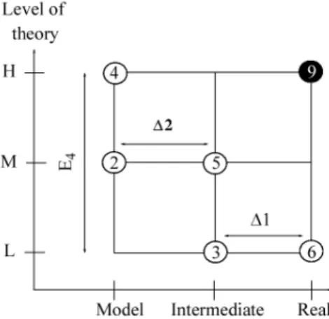
For example, in a three-layer model, ONIOM3, the energy is described in three parts according to the scheme given in Figure 3.
The improved system energy (E9 = EONIOM3) can be
obtained from, for example, three less sophisticated levels that are divided into three parts. The resulting expression is given by equation 1 with the application of the ONIOM method, with three levels of theory on three divisions of the molecule (model, intermediate and real) interest.
EONIOM3 = E6 – E3 + E5 – E2 + E4 (1)
Figure 1. Schematic representation of the “cinquefoil (51) knot”, an
interlaced pentagram.
Computational methods
The initial geometry of the pentafoil knot was obtained from experimental X-ray data.23 The geometry
of the molecule was fully reoptimized without imposing any constraints on the distances between the atoms. The geometry optimization was carried out at the ONIOM(M06/6-31G(2d,p):PM6) level of theory. The molecular system was then divided into two layers, which were treated with different model chemistries. The M06/6-31G(2d,p) level of theory was used to describe the high layer and the PM6 semiempirical method was employed for the low layer. The assignments for the former were defined by considering the atoms near the halide. In defining the two layers, the model system was represented by the structure [C4H6]5X–, where X = F, Cl, Br, and I.
Considering that the system is represented by two layers, the extrapolated energy EONIOM2 is defined as follows:
EONIOM2 = ERS:PM6 – EMOD:PM6 + ERS:M06/6-31G(2d,p) (2)
where ERS:PM6 is the energy of the real system (RS) obtained at
the lowest level of theory (Figure 4), the PM6 semiempirical method, and where EMOD:PM6 and ERS:M06/6-31G(2d,p) are the
energies of the model system (MOD) (Figure 5) determined
at the lower (PM6) and higher (M06/6-31G(2d,p)) levels of theory, respectively. Therefore, EONIOM2 is an approximation
of the calculated energy at the M06/6-31G(2d,p) level of theory for the real system. All of the calculations were performed at the ONIOM(M06/6-31G(2d,p):PM6) level of theory using the Gaussian09 program.31
Results and Discussion
The initial geometry of the [51 knot···(PF6)9]Cl
system was obtained from its experimental X-ray crystal structure.23 To analyze the electronic effects in the gas
phase, the molecular geometry was re-optimized. For X = F, Br, and I, the position of the chlorine atom was used as a reference and replaced by the corresponding halide.
Table 1 shows the calculated and experimental results of select average bond lengths (in Å) and bond angles (in degrees) for the molecular pentafoil knot. Although there is very good agreement between the calculated parameters and experimental data, the calculated values are slightly larger overall because they are obtained in the gas phase, whereas the experimental values come from the X-ray crystal structure.
The mean values of the bond lengths (in Å) and bond angles (in degrees) of [51 knot···(PF6)9]X (where X = F, Cl,
Br, and I) are shown in Table 2. For X = Cl, the available experimental data and calculated values are very similar, indicating a good description provided by the theoretical model. The Fe–X bond length increases in the order of 7.01, 7.33, 7.39, and 7.59 Å for X = F, Cl, Br, and I, respectively, whereas the θ[FeXFe] bond angle varies slightly in the same
sequence upon changing X: 71.44, 70.57, 70.39, and 69.42o.
This seems to indicate that as the electron cloud becomes more diffuse (from fluorine to iodine), there is an expansion of the central ring system to better accommodate the halide.
Considering a plane containing five atoms of Fe (σ5Fe),
the distance between the halide and the plane reflects the Figure 3. A three-layer model, ONIOM3.29
Figure 4. Molecular structure of the [51 knot···(PF6)9]X, X = F, Cl, Br,
and I. (a) Real system and (b) ONIOM model (RS = red + blue and MOD = blue).
Figure 5. Molecular structure of the [(C4H6)5Cl–] (model system). The
capacity of the pentafoil knot structure’s cavity to retain the halide. A measure of the capacity is provided by a structural model defined by a box containing the halide and plane. The calculated cell parameters of the model describing the positions of the five iron atoms and X = F, Cl, Br, and I inside a box of dimensions a, b and c are given in Table 3. The data show that the structure containing a fluorine anion is more compact than the structure with iodide. This effect is illustrated by the c values of fluorine and iodine, 3.11 and 4.21 Å, respectively. The stability of the iodine pentafoil knot is given by examining the process in which the anion
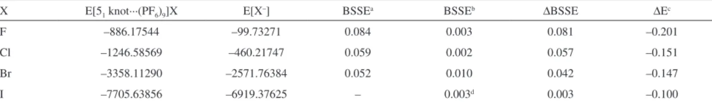
leaves the three-dimensional cavity. The close proximity of the halide anion to the atoms of the pentafoil knot seems to play a key role in determining the stabilization energies of the molecular system. Specifically, the closer the anion can approach, the more stable the molecular system becomes. This result can be observed directly by examining the electronic energies given in Table 4.
The most effective interaction occurs between the F anion and the pentafoil knot (–0.201 hartrees), followed by the systems containing Cl (–0.151 hartrees), Br (–0.147 hartrees), and I (–0.100 hartrees), respectively. This can also be interpreted by considering the Mulliken charges (in atomic units) of the halide atoms in the compounds, the values of which are –0.98,–0.96, –0.88, and –0.80 e for F, Cl, Br, and I, respectively. The Boys and Bernardi counterpoise correction (CP)34 was employed to remove
the “basis set superposition errors” (BSSEs). Considering the [(C4H6)5X–] systems model in which X = F, Cl, Br, and
I, the calculated values of BSSE at M06/6-311++G(2df,p) level of theory are 0.003, 0.002, 0.010, and 0.003 hartrees, respectively. The [(C4H6)5Br–] system model provided
the largest error associated with the deficiency of the function basis set (approximately 6.5 kcal mol-1). The
values associated with the BSSEs were employed for the calculations of the complexation energies and are included in Tables 4 and 5. These corrections to the complexation energies in the [51 knot···(PF6)9]Cl system using the
ONIOM(M06/6-31G(2d,p):PM6) method were considered for only the model system at the M06/6-311++G(2df,p) Table 1. Mean values of the bond lengths (in Å) and bond angles (in
degrees) of [51 knot···(PF6)10]
Parameters Calcd. Exp.21
R[Fe–Fe] 8.45 8.30
R[Fe–N] 2.00 1.96
R[C–O] 1.45 1.44
R[C–N] (ring) 1.34 1.36
R[C–N] 1.45 1.44
θ[NFeN] 88.36 85.28
θ[COC] 114.23 112.42
θ[CNC] (ring) 117.54 118.07
θ[CNC] 114.60 114.37
Table 2. Mean values of the bond lengths (in Å) and bond angles (in degrees) of [51 knot···(PF6)9]Cl
Parameters Calcd. Exp.21
R[Fe–F] 7.01 –
θ[FeFFe] 71.44 –
R[Fe–Cl] 7.33 7.21
θ[FeClFe] 70.57 70.56
R[Fe–Br] 7.39 –
θ[FeBrFe] 70.39 –
R[Fe–I] 7.59 –
θ[FeIFe] 69.42 –
Table 4. Electronic energies, BSSE and ∆E (in hartrees) of the [51 knot···(PF6)9]X; X = F, Cl, Br, and I.
X E[51 knot···(PF6)9]X E[X–] BSSEa BSSEb ∆BSSE ∆Ec
F –886.17544 –99.73271 0.084 0.003 0.081 –0.201
Cl –1246.58569 –460.21747 0.059 0.002 0.057 –0.151
Br –3358.11290 –2571.76384 0.052 0.010 0.042 –0.147
I –7705.63856 –6919.37625 – 0.003d 0.003 –0.100
aBSSE values based on CP method using M06/6-31G(2d,p); bBSSE values based on CP method using M06/6-31++G(2df,p); c∆E = E[51 knot···(PF6)]9X – (E[51 knot···(PF6)9]+ – E[X–]), where E[5
1 knot···(PF6)9]+ = –786.16029 hartrees. The interaction energies were calculated using the procedure described by
Kemp and Gordon,32 and ∆E was corrected with ∆BSSE; dthe basis set for the iodine atom was obtained from Glukhovtsev et al.33
Table 3. Calculated cell parameters (Å) of model describing the positions of the five iron atoms and X (X = F, Cl, Br, and I) inside a box of dimensions a, b and c
X a b c
F 15.37 15.18 3.11
Cl 15.84 15.76 3.84
Br 16.02 15.86 3.94
level of theory. The effects to the real and model systems on PM6 calculations were not included. This is because the molecular system described at the lower level (PM6) caused a similar influence, such as a reaction field.
The representation of the model system defined in the calculation by the high level theory exhibits great similarity to the molecular fragment present in the experimental structure. From the results given in Table 5, we can observe the same behavior in the stability of the model systems. The optimized molecular geometry of the [(C4H6)5Cl] system,
which is employed as the model system, is displayed in Figure 5.
The values of interaction energies reported, for example –0.201 hartrees (–126.130 kcal mol-1) for
E[51 knot···(PF6)]9F – (E[51 knot···(PF6)9]+ – E[F–]),
is similar to the other values considering analogous systems, where there is available information. Kemp and Gordon32 reported the experimental binding energies for
[F···(H2O)6]– and [Cl···(H2O)6]– complexes to be –94.9 and
–68.4 kcal mol-1, respectively. The calculated interaction
energy with [F···(H2O)17]– using the MP2/6-311++G(2df,p)
level of theory is –203.8 kcal mol-1.
The HC···Cl distances in the molecular system in which the chloride ion is located at the center of the X-ray crystal structure of [7Cl](PF6)9 are now considered. The ten HC···Cl
contacts have distances of 2.67, 2.76, 2.70, 2.69, 2.71, 2.71, 2.69, 2.71, 2.75, and 2.76 Å, whereas in the model system using the ONIOM method, the corresponding results are 2.60, 2.62, 2.62, 2.66, 2.60, 2.63, 2.65, 2.61, 2.63, and 2.62 Å.
Conclusions
Using DFT and semiempirical quantum chemical methods with an ONIOM approach (M06/6-31G(2d,p):PM6), we have studied the interactions between the halides X = F, Cl, Br, I and a pentafoil [51 knot···(PF6)10]+. From the equilibrium
geometries fully optimized by the ONIOM method, we have obtained excellent results for values of the bond distance, bond angle, and dihedral angle along the molecular structure when these variables are compared with the results obtained from X-ray data. We discovered trends of increasing distance,
R[FeX], and decreasing bond angle, θ[FeXFe], between
the atoms of iron and the halides, as we go from fluorine to iodine, respectively. These tendencies can be attributed to the increasingly diffuse character of the electronic cloud in the direction of fluorine to iodine, and an expansion of the central ring of the pentafoil knot to accommodate the halogen atom. The calculated relative energies show that of all the halogens, the most stable interaction occurs between the fluorine atom and the knot. The unstable structure that formed between the iodine atom and the pentafoil knot can also be attributed to the diffuse character of the iodine electronic cloud.
Acknowledgements
We thank the Chemistry Institute at UNICAMP and Grid/UNESP for providing computational facilities, and Fundação de Amparo à Pesquisa de São Paulo (FAPESP) and Conselho Nacional de Desenvolvimento Científico e Tecnológico (CNPq) for financial support.
References
1. Siegel, J. S.; Liang, C. Z.; Mislow, K.; Am, J.; Science2012,
338, 1287.
2. Taylor, W. R.; Lin, K.; Nature2003, 421, 25.
3. Ayme, J.; Beves, J. E.; Leigh, D. A.; Mcburney, R. T.; Rissanen, K.; Schultz, D.; J. Am. Chem. Soc.2012, 134, 9488. 4. Liu, L. F.; Depew, R. E.; Wang, J. C.; J. Mol. Biol.1976, 106,
439.
5. Flapan, E.; When Topology Meets Chemistry: A Topological Look at Molecular Chirality, Outlooks Series; Cambridge University Press: New York, NY, 2000.
6. Dobrowolski, J. C.; Mazurek, A. P.; Int. J. Quantum Chem. 1998, 70, 1009.
7. Adams, C. C.; The Knot Book: An Elementary Introduction to the Mathematical Theory of Knots; Henry Holt and Company:
Palo Alto, CA, 2000.
8. Scharein, R. G.; Booth, K. S. In Multimedia Tools for Communicating Mathematics; Borwein, J.; Morales, M. H.; Polthier, K.; Rodrigues, J. F., eds.; Springer: New York, NY,
2002, 17, 277.
Table 5. Electronic energies and ∆E (in hartrees) of the [(C4H6)5X–] model system; X = F, Cl, Br, and I
X E[(C4H6)5X-] E[(C
4H6)5]a E[X–] ∆Ec
F –879.20299 –779.29631 –99.73272 –0.171
Cl –1239.58691 –779.30081 –460.21759 –0.066
Br –3353.17756 –779.29963 –2573.82325 –0.047
I –7698.71419 –779.29869 –6919.37617 –0.037
aValues for the energies at Franck-Condon structures; bBSSE values based on CP method using M06/6-31++G(2df,p); c∆E = E[(C
4H6)5X–] – E[(C4H6)5] –
9. Frisch, H. L.; Wasserman, E.; J. Am. Chem. Soc.1961, 83, 3789. 10. Dietrichbuchecker, C. O.; Sauvage, J. P.; Angew. Chem., Int.
Ed. Engl.1989, 28, 189.
11. Ayme, J. F.; Beves, J. E.; Campbell, C. J.; Leigh, D. A.; Chem. Soc. Rev.2013, 42, 1700.
12. Beves, J. E.; Blight, B. A.; Campbell, C. J.; Leigh, D. A.; Mcburney, R. T.; Angew. Chem., Int. Ed.2011, 50, 9260. 13. Forgan, R. S.; Sauvage, J. P.; Stoddart, J. F.; Chem. Rev.2011,
111, 5434.
14. Krinas, C. S.; Demetropoulos, I. N.; Chem. Phys. Lett.2007, 433, 422.
15. Seeman, N. C.; Angew. Chem., Int. Ed.1998, 37, 3220.
16. Du, S. M.; Stollar, B. D.; Seeman, N. C.; J. Am. Chem. Soc. 1995, 117, 1194.
17. Bucka, A.; Stasiak, A.; Nucleic Acids Res.2002, 30, e24. 18. King, N. P.; Jacobitz, A. W.; Sawaya, M. R.; Goldschmidt, L.;
Yeates, T. O.; Proc. Natl. Acad. Sci. U. S. A.2010, 107, 20732. 19. Lukin, O.; Recker, J.; Bohmer, A.; Muller, W. M.; Kubota, T.;
Okamoto, Y.; Nieger, M.; Frohlich, R.; Vogtle, F.; Angew. Chem., Int. Ed.2003, 42, 442.
20. Craik, D. J.; Cemazar, M.; Daly, N. L.; Curr. Opin. Drug Discovery Dev.2006, 9, 251.
21. Bilbeisi, R. A.; Olsen, J.-C.; Charnonnière, L. J.; Trabolsi, A.;
Inorg. Chim. Acta2014, 417, 79.
22. Spickermann, C.; Felder, T.; Schalley, C. A.; Kirchner, B.;
Chem. - Eur. J. 2008, 14,1216.
23. Ayme, J.-F.; Beves, J. E.; Leigh, D. A.; Mcburney, R. T.; Rissanen, K.; Schultz, D.; Nat. Chem.2012, 4, 15.
24. Lehn, J.-M.; Supramolecular Chemistry, Concepts and Perspectives; VCH: Weinheim, 1995.
25. Svensson, M.; Humbel, S.; Froese, R. D. J.; Matsubara, T.; Sieber, S.; Morokuma, K.; J. Phys. Chem.1996, 100, 19357.
26. Kuno, M.; Hannongbua, S.; Morokuma, K.; Chem. Phys. Lett. 2003, 380, 456.
27. Fukaya, H.; Morokuma, K.; J. Org. Chem.2003, 68, 8170. 28. Kudo, T.; Akiba, S.; Kondo, Y.; Watanabe, H.; Morokuma, K.;
Vreven, T.; Organometallics2003, 22, 4721.
29. Braga, A. A. C.; Morgon, N. H.; Quim. Nova2006, 29, 187.
30. Dapprich, S.; Komaromi, I.; Byun, K. S.; Morokuma, K.; Frisch, M. J.; J. Mol. Struct.: THEOCHEM1999, 461, 1.
31. Frisch, M. J.; Trucks, G. W.; Schlegel, H. B.; Scuseria, G. E.; Robb, M. A.; Cheeseman, J. R.; Scalmani, G.; Barone, V.; Mennucci, B.; Petersson, G. A.; Nakatsuji, H.; Caricato, M.; Li, X.; Hratchian, H. P.; Izmaylov, A. F.; Bloino, J.; Zheng, G.; Sonnenberg, J. L.; Hada, M.; Ehara, M.; Toyota, K.; Fukuda, R.; Hasegawa, J.; Ishida, M.; Nakajima, T.; Honda, Y.; Kitao, O.; Nakai, H.; Vreven, T.; Montgomery, Jr., J. A.; Peralta, J. E.; Ogliaro, F.; Bearpark, M.; Heyd, J. J.; Brothers, E.; Kudin, K. N.; Staroverov, V. N.; Kobayashi, R.; Normand, J.; Raghavachari, K.; Rendell, A.; Burant, J. C.; Iyengar, S. S.; Tomasi, J.; Cossi, M.; Rega, N.; Millam, J. M.; Klene, M.; Knox, J. E.; Cross, J. B.; Bakken, V.; Adamo, C.; Jaramillo, J.; Gomperts, R.; Stratmann, R. E.; Yazyev, O.; Austin, A. J.; Cammi, R.; Pomelli, C.; Ochterski, J. W.; Martin, R. L.; Morokuma, K.; Zakrzewski, V. G.; Voth, G. A.; Salvador, P.; Dannenberg, J. J.; Dapprich, S.; Daniels, A. D.; Farkas, Ö.; Foresman, J. B.; Ortiz, J. V.; Cioslowski, J.; Fox, D. J.; Gaussian 09, Revision A.02; Gaussian, Inc.: Wallingford CT, 2009.
32. Kemp, D. D.; Gordon, M. S.; J. Phys. Chem. A2005, 109, 7688. 33. Glukhovtsev, M. N.; Pross, A.; McGrath, M. P.; Radom, L.;
J. Chem. Phys. 1995,103, 1878.
34. Boys, S. F.; Bernardi, F.; Mol. Phys.1970, 19, 553.
Submitted: October 15, 2014 Published online: March 20, 2015

![Table 5. Electronic energies and ∆E (in hartrees) of the [(C 4 H 6 ) 5 X – ] model system; X = F, Cl, Br, and I](https://thumb-eu.123doks.com/thumbv2/123dok_br/16344484.189120/5.892.66.799.149.256/table-electronic-energies-e-hartrees-model-cl-br.webp)
