50
PERFORMANCE OF ANN BASED INDIRECT VECTOR
CONTROL INDUCTION MOTOR DRIVE
1
A. K. Sharma, 2R. A. Gupta, 3Laxmi Srivastava
1
UCE, RTU, Kota, India
2
MNIT, Jaipur, India
3
MITS, Gwalior, India
Email: [email protected], [email protected], [email protected]
ABSTRACT
Indirect field orientation (IFO) induction machine drives are increasingly employed in industrial drive systems, but the drive performance is often degrades. Motor works on best performance at certain voltage and frequency for certain loads. In this paper artificial neural network is used to predict the operating voltage and frequency when the load torque and speed going changed so motor efficiency is increased. Simulation and experimental results are shown to validate the scheme.
I. INTRODUCTION
Because of their easy implementation and low cost, indirect field oriented (IFO) induction machine drives are finding numerous industrial applications. Most of the industrials motors are
used today are in fact induction motors. Induction
motors have been used in the past mainly in applications requiring a constant speed because conventional methods of their speed control have either been expensive or highly inefficient. Various methods have been designed to achieve the best performance of the motor and the approaches used can be classified into three different types. The first, so called “loss model controller” (LMC). The second type, named “search controller” (SC). The third one uses “look up tables”.
This type of control scheme uses more mathematical calculations and algorithms, which involves heavy computing and needed efficient and costly controllers. Here we introduce a novel theory to improve the performance of the motor running it at optimum voltage and frequency for optimum motor efficiency at different points. This is an offline method and not for online and real-time control.
The present paper proposed the new approach to optimize the efficiency by a control technique with the help of Artificial Neural Network (ANN). The ANN based controller gives the ratio of optimum value of voltage and frequency, which is used to determine the optimum flux operates the motor at
its maximum efficiency for given value of torque and speed.
Like the human brain an NN may be constructed with many artificial neurons. A neuron can be modeled to perform a mathematical function such as a pure linear function, step function, tan-sigmoid function etc. The attractive feature of NN is that it can be trained to solve complex nonlinear function with variable parameter, which may not be attainable, by conventional mathematical tools [5].
A computer mat lab program is developed for getting the ratio of optimum voltage and frequency. Neural Network is automatically trained itself by compare the actual voltage and frequency with the sample corresponding data. The motor flux is in the ratio of the ratio of optimum voltage and frequency. So this flux is compared with the reference flux and generates the error signal and control the action of the induction motor.
II. PERFORMANCE OF INDUCTION MOTOR
51
less internal heat, and run cooler and more quietly [6]. It is also likely to last longer and more reliable than a less efficient motor.
The better performance of the motor is related to the maximum efficiency of the motor. There are different methods to improve the performance of the induction motor. Variable speed drive (VSD) is most applicable technology for the improvement of motor performance. VSD is used to regulate the speed of a motor to suit with the load demand. A VSD offers the reduce power, wider speed, torque and power ranges, and shorter response time. Induction motor efficiency is dependent on many motor parameters; however it is a function of the operating speed and applied voltage, frequency.
So there is need to generate the appropriate values of optimum voltage and frequency for any operating point, and feed to the motor, which maximize the efficiency of motor.
Let’s considered the following definitions:
P : No. of poles
f0 : Base frequency (Hz)
Rs : Stator resistance (ohm)
Xs0 : Stator Leakage reactance at base frequency
(ohm)
R’r : rotor resistance, (ohm)
X’r0 : rotor leakage reactance at base frequency
(ohm)
Rc : core loss equivalent resistance (ohm)
Xm0 : stator to rotor mutual reactance at base
frequency (ohm)
ωm : is the rotor mechanical angular in mech.
(rad/sec)
T : Motor (Load) torque (Nm)
ωo = 2*ω /p = 4*π*ƒo /p
a = ƒ
/ƒo =
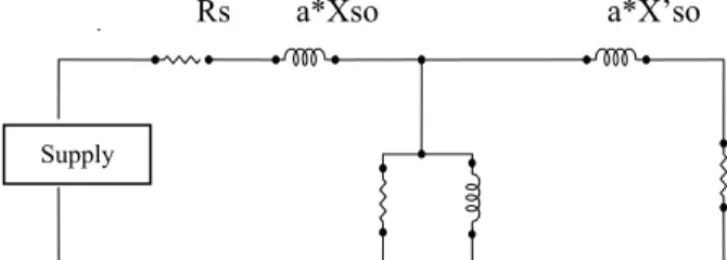
ωm /ωo (1-s)Based on above definition we can draw the
equivalent circuit
on induction motor shown fig. (1)Rs a*Xso a*X’so
Fig. 1. Equivalent circuit of induction motor
Stator Resistance Rs Stator leakage reactance a*Xso
Core Parameters Rm and a*Xmo Rotor Resistance R’r/s
Rotor leakage reactance a*X’so
Fig. (2) Shows an example of torque versus speed characteristics obtained for different sets of V and f
Note that motor parameters may change because of temperature variation or magnetic flux saturation. Thus, the
optimum voltage and frequency values may also change so the performance of the induction motor is also altered. In
this paper we will suppose that the effect of motor parameter variation is negligible and we will consider that motor parameters are constant.
Fig. 2. IM torque-speed characteristics under variable voltage and frequency control
II. ANN MODEL
Artificial Neural networks are relatively crude electronics models based on the neural structure of the human brain. The fundamental processing element of a neural network is a neuron. A neural net is based on layers of neurons. Once a network has been structured for a particular application, then the network is ready to be trained. To start this process the initial weights are chosen randomly. Then the training or learning begins [7].
Here, neural network is used for the compute the appropriate set of voltage and frequency to achieve
themaximum efficiency for any value of operating
torque and motor speed. NN have the two inputs, motor torque and speed and have two outputs, optimum voltage and frequency. The typical
52
layer architecture used for the firing angle calculation is shown in Fig. (3). It has a hidden layer of tansigmoidal neuron, which receives inputs (in this case the speed and the torque) directly, then broadcast their outputs to a layer of linear neurons, which compute the network output
(in this case fop and Vop). Since the optimum
voltage and frequency are highly non-linear function of motor speed and load torque so we preferred the tan-sigmoidal function
The patterns were generated by simulation using the computer program mentioned in fig. (5). The torque and speed were varied simultaneously within a practical range of motor operation. The
corresponding values of fop and Vop were
calculated. The results were saved in a data file in a matrix form with the torque, speed, voltage and frequency in the first, second, third and fourth columns respectively. The back-propagation training algorithm is used for this network. The training is automated with Matlab Simulation program developed for this purpose, which train the network using the back propagation method. At the end of training of network the value of weight and bias are set [8].
Fig. 3. Neural network model
Here are the parameters of the proposed ANN model
Input ωm, Te
Output fop, Vop
Maximum input value ωmax = 1(p.u.) Tmax =
1.5(p.u.)
Minimum input value ωmin = 0(p.u.) Tmin =
0(p.u.)
Maximum output value fmax = 1(p.u) Vmax =
1(p.u.)
Minimum output value fmin = 0(p.u) Vmin =
0(p.u.)
Functions Tansigmoidal + Linear
Hidden nodes 8
Number of samples 7104
Epochs 76
Mean square error 1x10⁻⁴
Network has a capability to learn ortrained from
a given set of input output pattern.. For this purpose we must have the good knowledge of the equivalent circuits of the induction motors parameters and the operating point limitations. The torque and speed should vary with in a practical limit corresponding the value of voltage and frequency is calculated and saved in a data file in matrix form. At the end of the training process (when the target mean squared error is reached), the model obtained consists of the weight and the bias vectors.
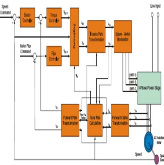
IV. VECTOR CONTROL
Vector control is the most popular control technique of AC induction motors. In special reference frames, the expression for the electromagnetic torque of the smooth-air-gap machine is similar to the expression for the torque of the separately excited DC machine. In the case of induction machines, the control is usually performed in the reference frame (d-q) attached to the rotor flux space vector. That’s why the implementation of vector control requires information on the modulus and the space angle (position) of the rotor flux space vector. The stator currents of the induction machine are separated into flux- and torque-producing components by utilizing transformation to the d-q coordinate
system, whose direct axis (d) is aligned with the
53
Fig. 4 Complete block diagram of Vector Control
To perform vector control, follow these steps:
• Measure the motor quantities (phase voltages and currents)
• Transform them to the 2-phase system (α ,β) using a Clarke transformation
• Calculate the rotor flux space vector magnitude and position angle
• Transform stator currents to the d-q coordinate system using a Park transformation
• The stator current torque- (isq) and flux- (isd)
producing components are separately controlled • The output stator voltage space vector is
calculated using the decoupling block
• An inverse Park transformation transforms the stator voltage space vector back from the d-q coordinate system to the 2-phase system fixed with the stator
• Using the space vector modulation, the output 3-phase voltage is generated
The components isα and isβ, calculated with a
Clarke transformation, are attached to the stator reference frame α,β In vector control, all quantities must be expressed in the same reference frame. The stator reference frame is not suitable for the control process. The space vector is is rotating at a rate equal to the angular frequency of the phase currents. The components isα and isα depend on
time and speed. These components can be transformed from the stator reference frame to the
d-q reference frame rotating at the same speed as the angular frequency of the phase currents. The isd
and isqcomponents do not then depend on time and
speed. The component isd is called the direct axis
component (the flux-producing component) and isq
is called the quadrature axis component (the
torque-producing component). They are time
invariant; flux and torque control with them is
easy.
Knowledge of the rotor flux space vector magnitude and position is key information for AC induction motor vector control. With the rotor magnetic flux space vector, the rotational coordinate system (d-q) can be established. There are several methods for obtaining the rotor magnetic flux space vector. The flux model implemented here utilizes monitored rotor speed and stator voltages and currents. It is calculated in the stationary reference frame (α ,β)attached to the stator. The error in the calculated value of the rotor flux, influenced by the changes in temperature, is negligible for this rotor flux model.
For purposes of the rotor flux-oriented vector control, the direct-axis stator current isd (the rotor
flux-producing component) and the
quadrature-axis stator current isq (the torque producing
component) must be controlled independently. However, the equations of the stator voltage components are coupled. The direct axis
component usd also depends on isd and the
quadrature axis component usqalso depends on isq.
The stator voltage components usd and usq cannot be
considered as decoupled control variables for the rotor flux and electromagnetic torque. The stator
currents isd and isq can only be independently
controlled (decoupled control) if the stator voltage equations are decoupled and controlling the terminal voltages of the induction motor indirectly controls the stator current components isd and isq.
V. SIMULATION AND RESULTS
For the simulation of the induction motor drive simulink model is developed Simulation model of the induction motor drive is shown. Drive model consist of induction motor, the load, the source and the proposed ANN model. Simulink model is run for some operating points only.
54
frequency but there is slight difference in the results because we have not taken the copper losses
in account.
Fig. 5. Flow chart
Start
Initialize variables
Calculated torque for rated voltage
Calculate required Voltage to produced load torque
Calculate ‘a’
Calculate required power to produces load torque
Compare input power to minimum power
Calculated maximum efficiency
55
0 0.5 1 1.5 2 2.5
x 106 -1500 -1000 -500 0 500 1000 1500 Time (Sec.) T o rqu e (N-m )
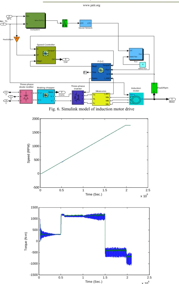
Fig. 6. Simulink model of induction motor drive
Fig. 7. Simulation results
0 0.5 1 1.5 2 2.5
x 106 -500 0 500 1000 1500 2000 Time (Sec.) Sp e e d ( R PM ) Three-phas e inverter Three-phas e diode rectifier 3 Ctrl 2 Conv. 1 Motor 3 C 2 B 1 A .8 rated flux V/F
rated f lux f lux flux Wm To Wm+To*0.1 Subsystem N N* MagC Torque* Ctrl Speed Controller A B C + -ZOH mN Rad2Rpm -K-Rad/s2Rpm
p{1} y {1}
56
In the figure 7 the comparision of actual value of parameter with the desired value of parameter is shown. The desired value is calculated by the ANN controller which is described in the section III. The input values to the ANN controller is the speed command and the torque command. They are called the reference values or the desired values. They are give in the form of pulses. The ANN controller calculated the optimum voltage and frequency corresponding to the maximum efficiency. The desired value of the parameter is shown by a PINK line in the graph.
The calculated values of the voltage and frequency runs the motor at it’s maximum efficiency. This is called the actual values which fluctuates around the desired values, shown by the YELLOW line in the graph. At the starting the electromagmetic torqur must be larger than the mechanical torque so the corresponding value at the starting jumps above the reference value. The motor gets its rated speed and torque after some time. The corresponding stator current is also shown in the graph. As trhe value of torque is changed the value of the stator current is also changed. The corresponding values of the stator current is sligthly damped down asfter some time.
V. CONCLUSION
This paper proposed a advance control theory applied with an ANN model on a induction motor. The proposed scheme requires the information of the motor load torque and speed and generate the optimum value of voltage and frequency. The ANN model is configured and trained with some input output pattern. The ANN model is used is a two layer feed forward network, first layer is a tan-sigmoidal layer and have 8 neurons and another is of linear neuron. Computer matlab program is developed to generate the required pattern for training. The trained network was validated by simulation using Matlab/Simulink. In the simulation of induction motor drive indirect vector control strategy is used. The proposed technique is easily implemented on induction motor. The validity of the proposed control technique has been established both in simulation and experiment at different operating conditions. There is a close agreement between simulation and experimental results and shows the dynamic behavior of the system.
VI. REFERENCES
[1]. F.J.Nola, “Power factor Control System
for AC Induction Motor, “U.S.Patent 4 052 648, Oct 4,1977
[2]. Alexander Kusko, Donald Galler,”Control
Means For Minimization of Losses in AC
and DC Motor Drives”, IEEE Trans. Ind.
Appl., vol. LA-19, No. 4, July/August 1983
[3]. Iordanis Kioskeridis, Nikos Margaris,
“Loss Minimization in Induction Motor
Adjustable-Speed Drives”, IEEE Trans.
Ind. Electron, vol. 43, No. 1, Februry 1996
[4]. Iordanis Kioskeridis, Nikos Margaris,
“Loss Minimization in Scalar- Controlled Induction Motor Drives with Search Controllers, “IEEE Trans. Ind. Electron, vol. 11, No. 2, March 1996
[5]. K.M.Hasan, Li Zhang, B. Singh, “Neural
Network Control of Induction Motor Drives for Energy Efficiency and High Dynamic Performance”.
[6]. D.M.Breathauer, R.L.Doughty and
R.J.Puckett, “The Impact of Efficiency on the Economics of New Motor Purchases, Motor Repair, and Motor Replacement,
“IEEE Trans. Ind. Appl., vol. 30,
Nov./Dec. 1994, pp. 1525-1537.
[7]. H.A.Al-Rashidi, A.Gastli, A.Al-Badi,
“Optimization of Variable Speed Induction Motor Efficiency Using Artificial Neural Network”.
[8]. Howard Demuth, Mark Beal, “Neural
Network Toolbox For Use With Matlab”, User Guide, The Math Work Inc. June 1992
[9]. B.K.Bose, “Modern Power Electronics
and AC Drives”.
[10]. Dan W. Patterson, “Introduction
57
Appendix
The induction motor is ¼ hp having following parameters
P =4 No. of poles
f0 =60 Base frequency (Hz)
Vs=460/1.73 Rated Voltage (V)
T=807 Rated Torque (Nm)
Rs = 0.01485 Stator Resistance (ohm)
R’r=0.009295 Rotor resistance (ohm)
Rc=2000 Core loss equivalent resistance (ohm)
ls:=0.0003027 Stator Leakage Inductance at base frequency (H)
l’r = ls Rotor Leakage Inductance at base frequency (H)
Lm=0.01046 Constant Mutual Inductance (H)