Abstract— In this paper, an Adaptive Neural Network Sliding
Mode Controller (ANNSMC) design approach is proposed. Sliding mode control method is studied for controlling DC motor because of its robustness against model uncertainties and external disturbances, and also its ability in controlling nonlinear and MIMO systems. The main drawback of SMC is a phenomenon, the so-called chattering, which can excite unmodeled dynamics and maybe harm the plan, and sliding mode control cant adapt on desired position against external load torque. Different approaches are used to abate these drawbacks such as adaptive neural network and boundary layers. So the chattering is avoided and response of system is improved against external load torque here. Presented simulations results confirm the above claims and demonstrate the performance improvement in this case.
Index Terms— Adaptive control, DC motor, neural network, robust control, sliding mode.
I. INTRODUCTION
In the industrial processes there are many systems having nonlinear properties. Moreover, these properties are often unknown and time varying. The commonly used proportional-Integral-Derivative (PID) controllers are simple to be realized, but they suffer from poor performance if there are uncertainties and nonlinearities [1].
Recently much research has been devoted to the robust control systems, where the fuzzy logic, neural network and sliding-mode based controllers are applied [2-6].
The sliding mode control is robust to plant uncertainties and insensitive to external disturbances. It is widely used to obtain good dynamic performance of controlled systems. However, the chattering phenomena due to the finite speed of the switching devices can affect the system behavior significantly. Additionally, the sliding control requires the knowledge of mathematical model of the system with bounded uncertainties. Another method, popular in recent years, is based on [7-10].
The neural network controllers have emerged as a tool for difficult control problems of unknown nonlinear systems. Neural networks (NN) are used for modeling and control of complex physical systems because of their ability to handle
Manuscript received January 10, 2009.
Mohsen Fallahi is with the Department of Mechatronics Engineering, Semnan University, Semnan, Iran, (phone:0989173184529; e-mail:[email protected])
Sasan Azadi is with the Department of Electrical Engineering, Semnan University, Semnan, Iran, (e-mail: [email protected], [email protected]).
.
complex input-output mapping without detailed analytical models of the systems [11,12]
There are many types of dc servo motors used in the industries in which rotor inertia is can be very small, and in this result, motors with very high torque – to – inertia ratios are commercially available. Servo systems are generally controlled by conventional Proportional – Integral – Derivative (PID) controllers, since they designed easily, have low cost, inexpensive maintenance and effectiveness. It is necessary to know system’s mathematical model or to make some experiments for tuning PID parameters. However, it has been known that conventional PID controllers generally do not work well for non-linear systems, and particularly complex and vague systems that have no precise mathematical models. To overcome these difficulties, various types of modified conventional PID controllers such as auto-tuning and adaptive PID controllers were developed lately. Also Fuzzy Logic Controller (FLC) can be used for this kind of problems. When compared to the conventional controller, the main advantage of fuzzy logic is that no mathematical modeling is required.
In this paper the combined solution we have proposed and designed a robust and adaptive controller. We have used an adaptive linear neural network and a sliding mode controller with a boundary layer in the control law [13-15].
II. MODEL OF A DC MOTOR
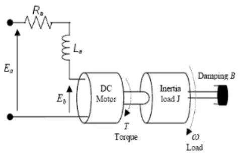
DC motors are widely used in industrial and domestic equipment. The control of the position of a motor with high accuracy is required. The electric circuit of the armature and the free body diagram of the rotor are shown in fig. 1
Fig. 1: The structure of a DC motor
A desired speed may be tracked when a desired shaft position is also required. In fact, a single controller may be required to control both the position and the speed. The reference signal determines the desired position and/or speed. The controller is selected so that the error between the system output and reference signal eventually tends to its minimum
Adaptive Control of a DC Motor Using Neural
Network Sliding Mode Control
value, ideally zero. There are various DC motor types. Depending on type, a DC motor may be controlled by varying the input voltage whilst another motor only by changing the current input.
In this paper a DC motor is controlled via the input voltage. The control design and theory for controlling a DC motor via current is nearly the same. For simplicity, a constant value as a reference signal is injected to the system to obtain a desired position. However, the method works successfully for any reference signal, particularly for any stepwise time-continuous function. This signal may be a periodic signal or any signal to get a desired shaft position, i.e. a desired angle between 0 and 360 degrees from a virtual horizontal line.
The dynamics of a DC motor may be expressed as:
a a a a a t
E
dt
dI
L
I
R
V
=
+
+
(1)l
T
B
dt
d
J
T
=
ω
+
ω
−
(2)a T
I
K
T
=
(3)ω
a a
K
E
=
(4)φ
ω
=
dt
d
(5) With the following physical parameters:Ea: The input terminal voltage (source), (v); Eb: The back emf, (v);
Ra: The armature resistance, (ohm); Ia: The armature current (Amp); La: The armature inductance, (H);
J: The moment inertial of the motor rotor and load, (Kg.m2/s2);
T: The motor torque, (Nm)
ω
: The speed of the shaft and the load (angular velocity),(rad/s);
φ
: The shaft position, (rad);B: The damping ratio of the mechanical system, (Nms); T k: The torque factor constant, (Nm/Amp);
B k : The motor constant (v-s/rad).
Block diagram of a DC motor is shown in fig. 2
Fig. 2: The block diagram of a DC motor
III. SLIDINGMODECONTROL
A Sliding Mode Controller is a Variable Structure Controller (VSC). Basically, a VSC includes several different continuous functions that can map plant state to a control.
Surface and the switching among different functions are determined by plant state that is represented by a switching function. Without lost of generality, consider the design of a sliding mode controller for the following second order system: Here u (t) is the input to the system:
eq s
u
u
u
=
+
(6) Whereu
s=
−
k
.
sat
(
s
/
φ
)
and constant factorφ
defines the thickness of the boundary layer.sat
(
s
/
φ
)
Is a saturation function that is defined as:> ≤ = 1 ) / sgn( 1 ) / ( φ φ φ φ φ s if s s if s s
sat (7)
The function between us and
s
/
φ
is shown in the fig. 3:Fig. 3: Switching surface in the phase plane
The control strategy adopted here will guarantee the system trajectories move toward and stay on the sliding surface s = 0 from any initial condition if the following condition meets:
s
s
s
≤
−
η
.
(8) Where
η
is a positive constant, which guarantees the system trajectories hit the sliding surface in finite time. Using a sign function often causes chattering in practice. One solution is to introduce a boundary layer around the switch surface.This controller is actually a continuous approximation of the ideal relay control. The consequence of this control scheme is that invariance of sliding mode control is lost. The system robustness is a function of the width of the boundary layer.
The principle of designing sliding mode control law for arbitrary-order plants is to make the error and derivative of error of a variable is forced to zero. In the DC motor system, the position error and its derivative are the selected coordinate variables those are forced to zero. Switching surface design consists of the construction of the switching function. The transient response of the system is determined by this switching surface if the sliding mode exists. First, the position error is introduced:
)
(
)
(
)
(
k
k
k
the desired reference track and actual rotor position, at the k the sampling interval and e (k) is the speed error. The sliding surface (s) is defined with the tracking error (e) and its integral (
edt
) and rate of change (.
e
)+
+
=
e
e
edt
s
1 2.
λ
λ
(10) Whereλ
1,
λ
20
are a strictly positive real constant. Thebasic control law of Sliding Mode Controller is given by U=-ksgn(s) (11)
Where K is a constant parameter, sgn (·) is the sign function and S is the switching function.
IV. ADAPTIVE LINEARNEURALNETWORK Adaptive linear networks are very simple artificial neural network that contains just one neuron with a few inputs and additional unit signal. Linear function is used as a transfer function. Due to limited skills of this structure Widrow and Hoff connected more of ADALINE’s together and gave it a name MADALINE (Multiple ADALINE). Block diagram of an adaline network is shown in fig. 4.
Despite the fact that ADALINE is able to solve only linearly separable problems, it has been shown in practice that they can approximate nonlinear functions with sufficient accuracy while using enough number of neurons. Because of their main advantage, that is very fast learning.
The most popular learning method is simple LMS (Least Mean Square) algorithm (Windrow & Hoff, 1960), often called the Widrow-Hoff Delta Rule (Rumelhart et al., 1986), which is adopted in this paper. This method is based on the minimization of Mean Square Error (MSE).
T k k
X
e
k
w
k
w
(
+
1
)
=
(
)
+
η
'
(12)k
e
k
b
k
b
(
+
1
)
=
(
)
+
η
'
(13) Whereη
, gain rate andX
k is network input vector. Where W (k) is previous weighting matrix, b (k) is previous bias vector.Fig. 4: block diagram of an adaline
V. DESIGNOFADAPTIVENEURALNETWORK
SLIDINGMODECONTROLLER
In other to design a neural network sliding mode controller, we combine adaptive linear neural network and sliding mode
controller. We use output of sliding mode controller to train the adaptive linear neural network.
])
([ 2 3
.
1 + +
−
= K sign e e edt
usmc σ
λ
λ
λ
(14)
2
^
)
(
)
1
(
K
W
K
u
smcW
+
=
+
η
(15)]
2
^
)
(
[
[
)
(
smc i a smcnnsmc
u
k
I
f
w
k
u
u
=
−
+
η
(16)Every controller abates drawbacks of another controller and improves the control application of a DC motor, and we can use advantages of both of controllers. The structure of sliding mode controller is shown in fig. 5 and the block diagram of ALNN is shown in fig. 6.
Fig. 5: The block diagram of SMC
Fig. 6: The structure of ALNN
VI. SIMULATIONRESULT
We design the proposed controller in MATLAB/simulink. To show uncertainties in model, we change the parameters of DC motor and to show external disturbances and external load torque, we use “random number” block with variance 10. Fig.7 is shown external disturbance and load torque to force to DC motor.
Fig. 7: external disturbances and load torque
Although high gain rate lead to reduce training time but increase overshoot and settling time, so to compare ALNN and ANNSMC, we use gain rate
η
=
.
1
, so we present the response of a DC motor using ALNN, SMC, PID and ANNSMC. Fig. 8 shows the block diagram of ANNSMC with external load torque to control a DC motor.Fig. 8: block diagram of ANNSMC
Fig. 9 shows the response of ALNN, PID, SMC, ANNSMC without Uncertainties, disturbances and external load torque, fig. 10 shows response of system against uncertainties in the system, fig, 11 shows the disturbance rejection of controllers. Fig. 12 shows the response of the system PID and SMC and fig.13 shows the response of ALNN controller and ANNSMC with a load torque.
Fig. 9: Simulation results comparison between the PID, SMC, ALNN and ANNSMC controller of a DC motor
Fig. 9: Simulation results comparison between the PID, SMC, ALNN and ANNSMC controller of a DC motor with uncertainties
Fig. 9: Simulation results comparison between the PID, SMC, ALNN and ANNSMC controller of a DC motor with external disturbance
Fig. 9: Simulation results comparison between the PID, SMC controller of a DC motor with external load torque
Fig. 9: Simulation results comparison between the ALNN and ANNSMC controller of a DC motor with external load torque
against uncertainties and external load torque but its sensitivity against uncertainties is low and it can adapt on desired position soon but against external load torque is very sensitive and adapt on desired silently. its settle timing is lower than SMC and is the same with proposed controller(ANNSMC). Adaptive neural network sliding mode controller can provide the properties of insensitivity and robustness to uncertainties and external disturbances and can track desired trajectory against external load torque fast.
VII. CONCLUSION
In this paper, the adaptive neural network sliding mode controller proposed to control a DC motor, so we compare proposed controller with PID, classic SMC and ALNN, The simulation results proved that proposed controller is a robust and insensitive controller and is very well suited for systems with uncertain or unknown variations in plant parameters and structure and against disturbances and ANNSMC satisfactory trajectory tracking can be achieved effectively against external load torque, and the high frequency chattering in the control input is eliminated by using the boundary layer technology. The proposed scheme combines the benefits of the adaptive control, NN and Sliding Mode Control.
REFERENCES
[1] Mehmet Karadeniz,, res skender, Selma Yüncü, “ADAPTIVE NEURAL NETWORK CONTROL OF A DC MOTOR”, Gazi University, Faculty of Engineering & Architecture, Department of Electrical & Electronics Engineering, 06570 Maltepe, Ankara TURK YE,
[2] S.S. Ge, J. Zhang, Neural-network control of no affine nonlinear system with zero dynamics by state and output feedback, IEEE Trans. Neural Networks 14 (4) (2003) 900–918.
[3] Seung- Min Baek and Tae-Yong Kuc,"An Adaptive PID Learning Control of DC Motor", Intelligent Control and Dynamic Simulation Lab,440-746,KOREA
[4] Paul I-Hai Lin,Santai Hwang and John Chou, "COMPARISON ON FUZZY LOGIC AND PID CONTROLS FOR A DC MOTOR POSITION CONTROLLER" Indiana-Purdo University Fort Wayne. [5] NORHAZIMI BINTI HAMZAH," ANTILOCK BRAKING
CONTROL USING ROBUST CONTROL APPROACH", Faculty of Electrical Engineering Universiti Teknologi Malaysia, NOVEMBER 2006
[6] Mehmet Karadeniz and res skender and Selma Yüncü," ADAPTIVE NEURAL NETWORK CONTROL OF A DC MOTOR", Gazi University, Faculty of Engineering & Architecture, Department of Electrical & Electronics Engineering,06570 Maltepe, Ankara TURK YE
[7] Koshkouei, A. J. and Zinober, A. S. I., sliding mode controller-observer design for SISO linear systems. Int. J. systems Science, 29, 1363-1373, 1998.
[8] Drakunov, S. V. and Utkin, V. I., Sliding mode control in dynamic systems. Int. J. Control, 55, 1029-1037, 1992.
[9] T.C. Manjunath," Design of Moving Sliding Surfaces in A Variable Structure Plant & Chattering Phenomena", International Journal of Electronics, Circuits and Systems Volume 1 Number 3,
[10] Mohammed Golam Sarwer, Md. Abdur Rafiq and B.C. Ghosh," Sliding Mode Speed Controller of a D.C Motor Drive", Journal of Electrical Engineering, The Institution of Engineers, Bangladesh ,Vol. EE 31, No. I & II, December 2004
[11] M.D. Minkova, D. Minkov , J.L. Rodgerson, R.G. Harley,” Adaptive neural speed controller of a dc motor’, Department of Electrical Engineering, Uni6ersity of Natal, Durban 4014, South Africa
Received 23 February 1998; accepted 30 March 1998
[12] Khaled Nouri , Rached Dhaouadi , Naceur Benhadj Braiek ,” Adaptive control of a nonlinear dc motor drive using recurrent neural networks,
Received 7 May 2006; received in revised form 30 January 2007; accepted 4 March 2007 Available online 7 March 2007, ELSEVIER [13] Ali J. Koshkouei and Keith J. Burnham," CONTROL OF DC
MOTORS USING PROPORTIONAL INTEGRAL SLIDING MODE", Control Theory and Applications Centre, Coventry University, Coventry CV1 5FB, UK
[14] Bogumila Mrozek and Zbigniew Mrozek," Modelling and Fuzzy Control of DC Drive", 14-th European Simulation Multiconference ESM 2000, May 23-26, Ghent, pp186-190