DOI : 10.5121/ijdps.2011.2621 237
Moez ATTIA
1and Rihab CHATTA
2Engineering School of Communication of Tunis (Sup’Com), Ghazala Technopark, 2083, Ariana, Tunisia
1
[email protected], [email protected]
A
BSTRACTWe report a single photon source model which consists on InAs/GaAs pyramidal quantum dot (QD) model based on effective mass theory to calculate the emitted photons energies. We study the choice of geometrics parameters of QD to obtain emission at 1550 nm. This quantum dot must be embedded on a microcavity to improve the live time of photon at 1550 nm and inhibit the others photons to increase the probability to obtain only one emitted photon. We present two kinds of microcavities; the first based on two dimensional photonic crystal over GaAs, we study the geometric parameters choice to obtain a height density of mode (DOM) at 1550 nm; the second microcavity is based on microdisk structure over GaAs we evaluate the impact of radius variation to obtain whispering-gallery mode at 1550 nm. This study can serve for the conception of new quantum communications protocols.
K
EYWORDSSingle photon source, Quantum dots Microcavity, Microdisk, Photonic crystal
1.
I
NTRODUCTIONDeveloping techniques to improve the treatment capacity of computers and building up infrastructures and protocols to increase the bit rate of telecommunications networks and ensure the security of transport, is one of the most important focuses of researchers and engineers. Quantum information is a new area of research that aims to take advantages of the possibilities offered by quantum mechanics to treat information more efficiently. Two main research axes are developed: quantum communications, which provide better security over classic cryptosystem [1], and quantum computing, which are new algorithms based on the principal of quantum mechanics proposed for reducing the time processing to resolve some problems [2].
The philosophy of quantum communications and quantum processing is developed thanks to q-bit, in classical numeric component and communication systems the unit of information is the bit (a bit can have two values 1 or 0), but in quantum system the basic unit of information is the q-bit, it’s a superposition of states of 0 and 1. The quantum element easiest to handle is the photon, the value of q-bit depend of polarization of the photon. To produce quantum application single photon source must be developed. Two kinds of sources can be used a heralded single photon source [3] or on demand single photon source. In this work we focus on the second source kind.
238 absorption measurements on InAs quantum dots show that the dipole is of the order of 9.10-19 cm [5], what is two times higher than typical values of atoms emitting in the same energy range. Second the emission wavelength depends on the size of quantum dot; the size precision cannot be infinitely controlled. Instead of placing one dot in a cavity which is very complicated approach, its more practical to place a hundred dots, where the statically distribution of sizes leads to a statically distribution of emission wavelengths. It will be easy to obtain a desired wavelength. Finally, contrary to atoms, quantum dots can be excited in a no resonant high energy. The presence of phonons provides a relaxation and makes easy the capture in quantum dot of photo created electron-hole pairs.
The quantum dot must be embedded in resonant structure to improve the probability to obtain only one photon emitted, and to eliminate the non desired photons. There are many resonant microcavities structures: micropile, microdisk, cavity based on photonic crystal…Cavities based on photonic crystals are periodic structures of holes over semiconductor substrate. The most characteristic of this kind of structures is photonic band gap (PBG) for the propagation of light. The period of the holes in these structures is of the order of the wavelength of the photon, when we create a default in the periodicity the field will be confined in the default zone of the structure. For photonic crystal cavity a quality factor Q has been measured as Q=2800 [6]. The second component can be used as microcavity is the microdisk: it’s a structure where the whispering gallery modes are established by total reflection on the walls of microdisk. Microdisks can offer a height confinement of lights more important than micropiles [7].
In this paper we present a model of demand single photon source based on InAs quantum dot embedded in GaAs microcavity.
The remain parts of this paper are organized as follow: the first section presents the principal of single photon emission, we present our quantum dot model based on effective mass model to design QD emit a single photon at 1550 nm, in the second section we show two microcavities models the first is a photonic crystal model based on FDTD method we study the performance of this structure to be associated with QD to form our single photon source, the second is a microcavity structure consists on a microdisk. Finally, the fourth part concludes this paper.
2.
Q
UANTUMD
OTSM
ODEL2.1. Basics of quantum dots and effective Mass Model
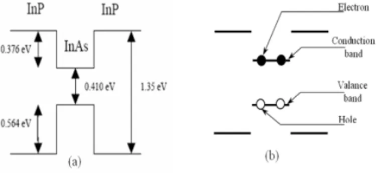
239 Figure 1. a) The diagram band of InAs/InP quantum dot b) The last two excitons in the quantum
dots
When the quantum dot is optically excited, electrons and holes are confined in the quantum dot. They occupy respectively conduction and valance bands. Electrons and holes return out, beginnings by those have the highest energies. Finally, it remains only two pairs of electron-hole. The two last photons to be emitted have a well defined energy: they are the alone to emerge from fundamental state of quantum dot. They correspond to recombination of an excitant, in presence or not of the second excitant in the quantum dot as illustrate by figure 1.b. The Colombian interaction, between load porters makes, this desexcitation products two photons with a little energy difference.
We design a three dimensional InAs pyramidal quantum dot in GaAs cubed matrix as showed in figure 2. The InAs nanostructures can present an important electronic confinement potential, associated with GaAs substrate. In this kind of structures electrons and holes are confined to permit the quantification of energy levels.
Figure 2. InAs pyramidal Quantum dot embedded in GaAs matrix
The goal of this part is to calculate the energies levels of the electrons and holes confined in the quantum dot, to calculate the energies of photons emitted caused by the recombination of electrons and holes. The governing equation is the Schrödinger equation given by equation 1:
(1)
GaAs matrix
240 Where the reduced plank constant, is is is the unknown eigenvalue and u(r) the corresponding eigenfunction. Here the effective mass m(r, ) and the confinement potential V(r) are discontinuous across the heterojonction. In the small wave number limit, m(r, ) can be approximated by the effective mass at the Brillouin zone center. Equation 2 and 3 give respectively the expressions of m(r, ) and V(r), which are both constant functions of r.
(2)
, are the effective mass and the confinement potential in the dot. , are the confinement potential in the matrix. We have a volume contained a pyramid InAs quantum dot embedded in GaAs cube matrix. We descretizate the volume according X,Y and Z axes. We write the Schrödinger equation in different parts of this volume. To resolve discontinuity of
we use Ben Daniel-Duke condition [9]:
(3)
2.2. Our pyramidal quantum dot model based on Schrödinger equation development
The Schrödinger equation given in equation (1) can be rewritten as illustrated in equation 4.
(4)
Where and represent the surface averages of α and the volume average of V over the controlled volume element respectively. To discretize the volume compound by the cube matrix included the quantum dot, we use a spatial discretization with uniform mesh = = . We write the equation 4 in different parts of the volume. Equations 5 to 14 represent the Schrödinger equation in different parts of pyramid.
• In exterior of pyramid
)+
)+
) = (5)
• In interior of pyramid
)+
)+
) = (6)
241 )+
)+
) = (7)
• On southern surface of pyramid
)+
)+
) = (8)
• On bottom surface of pyramid
)+
) = (9)
• On southwestern edge of pyramid
)+
) = (10)
• On western edge at the bottom of pyramid
)+
) = (11)
242
)+
) = (12)
• On Southwestern corner at the bottom of pyramid
)+
)+
) = (13)
• On the tip of pyramid
)+
) = (14)
Equation 15 represent a general shape of the different last equations which i, j,k represent the location on the cubed matrix points, Xm, Yp, Ym, Yp, Zm, Zp, A1, A2, A3, K1and K2 are constants
according to the zone and take care of the boundary conditions of this zone:
)+
)
= (15)
We approximate the effective mass of InAs and GaAs as constant, the same for and . We obtain a linear eigenvalue problem illustrated by equation 16:
(16)
M0 is a sparse matrix with non zero entries located in the main diagonal and six off-diagonals.
M0 is symmetric and positive definite, the eigenvalue are all positive. The matrix size depends
243 = M B B M B C C B M B B M C C C C M B B M B C C B M B B M M 2 1 2 2 2 1 2 1 2 2 1 1 2 1 2 1 1 1 2 1 0 0 0 0 0 0 0 0 0 0 0 0 0 0 0 0 0 0 0 0 0 0 0 0 0 0 0 0 0 0 0 0 0 0 0 0 0
M, B1, B2, C1 and C2 are matrixes T×T:
=
C
Z
Z
C
Z
Z
C
Z
Z
C
M
m p m p m p0
0
0
0
0
0
=
p p p pY
Y
Y
Y
B
0
0
0
0
0
0
0
0
0
0
0
0
1=
m m m mY
Y
Y
Y
B
0
0
0
0
0
0
0
0
0
0
0
0
2=
p p p pX
X
X
X
C
0
0
0
0
0
0
0
0
0
0
0
0
1=
m m m mX
X
X
X
C
0
0
0
0
0
0
0
0
0
0
0
0
2The shape of F is presented as:
[
]
T T S R S R T T S S T T u u u u u u u u u u F , , 1 , , , 1 , 2 1 , 1 , 2 , , 1 1 , , 1 , 2 , 1 1 , 2 , 1 , 1 , 1 1 , 1 , 1 .. .. .. .. .. .. .. =2.3. Simulation and results
In this part, we simulate our model and we study the influence of QD geometric parameters over the eigenvalue corresponding to electrons and holes energy states. We simulate a InAs pyramid structure, the width of the QD base is 12.4 nm and the height of the QD is 6.2 nm, for the constant effective mass model m*n=0.024m0, m*p,h =0.4m0 [10] and (Vin=0.0). This pyramid is
embedded in a GaAs cuboid matrix with a size of (24.8×24.8×18.6) nm, for the constant effective mass model m*n=0.067m0, m*p,h =0.5m0 and (Vout=0.7). x=24.8/R, y=24.8/S and z=18.6/T.We study, the influence of the dimensions of our structure over the eigenvalue. Other the dimensions of last structure (struct 1), we simulate two QD structure with different
S×T
244 size. Struct 2: the cubed matrix dimensions are (12.4×12.4 ×9,3) nm, the width of the pyramid base is 6,2 nm and the height is 3,1 nm. Struct 3: the cubed matrix dimensions are: (49.6×49.6×37.2) nm, the pyramid base width is 24.8 nm the height is 12.4 nm. Results for Ee
and Eh are summarized respectively in table 1 and table 2.
Table 1. Eignevalue corresponding to Ee results over various size of the quantum dot structure
(eV) Size 1 Size 2 Size 3
e1 0.78043 1.3794 0.49257 e2 1.0392 10.017 0.71916 e3 1.0423 10.036 0.72137
Table 2. Eignevalue corresponding to Eh results over various size of the quantum dot structure
(eV) Size 1 Size 2 Size 3
h1 0.28418 0.58726 0.10009 h2 0.44263 0.82266 0.15807 h3 0.44333 0.82554 0.15826
Results show that if we increase the dimension of the QD we decrease the eigenvalue corresponding to electrons and holes energy levels. The spin of electron is Jz =±1/2, the spin of heavy hole is Jz=±3/2, the spin of light hole is Jz =±1/2. The spin of the photon is Jz =±1. We must consider the heavy holes to conserve the angular moment. We obtain two radiative transitions Jz =±1 and two non-radiative transitions with Jz =±2. Each one transitions give one photon with different circular polarization.
(17)
The photon energy caused by the recombination of the electron and hole of the fundamental state is given by equation 17. Where Ex is the photon energy, Ee: the electron energy, Eh is the
hole energy and Jeh is the Colombian interaction between the electron and hole in order to
10 eV. For this different structures with different dimensions the photon energy of the fundamental state are shown in table 3.
Table 3. The photons energy of different structures
Size 1 SSiizzee22 Size 3 Ex(eV) 0.49624 00..7799221133 0.3824
Ex(nm) 2498 11556666 3242
The nearest value to 1550 nm is given by the second structure. The QD cannot form a single photon source, because there are many photons emitted by (the excitant, biexctent…), this quantum dot will be imbedded in microcavity structure, to strengthen the life time of photons at 1550 nm, and filter others photons to obtain a single photon source with probability to obtain a single photon at 1550 nm P1 nearly one value.
3.
M
ICROCAVITIES MODELS245 important demand for these devices to be useful. Thanks to the microelectronics development, now, it is feasible to fabricate high-quality devices.
3.1 Photonic crystal cavity model
A photonic crystal is defined by a refractive index modulation. This periodicity variation must be in order of the wavelength and can be on one or more directions space. The term “photonic” indicates the applications of these structures acting on the light propagation, “crystal” for the periodicity of unities structures. This kind of structures can be applied to develop some optical functions: filtering, multiplexing... and can be used as resonant structures by the presence of default in the periodicity arrangement. The presence of default in the photonic crystal allows the existence of modes with close frequency band. The introduction of default consists on a modification of the periodicity in the structure. For example, if a punctual default is introduced in the periodic arrangement of holes and if we excite this default with frequency throughout the photonic band gap, the energy light cannot escape and will be trapped by the perfect reflective walls formed by the photonic crystal. The energy light is confined in both directions of plane of periodicity. To prevent energy to escape from the structure, we can place the photonic crystal between two metallic structures. In conclusion a photonic crystal with punctual default can be used as a resonant cavity and confine the light energy in close frequency band. A simple modification of material proprieties (application of electric field) will free the light concentrated in the default. For a bidimensional photonic crystal the electric constant can be written as given in equation 18.
)
(
)
(
r
a
iε
r
ε
+
=
{
i=1,2}
(18)Equations 19 and 20 give the Maxwell equations.
{
(
)
}
(
)
)
(
1
2 2r
E
C
r
E
r
ω
ε
∇
×
∇
×
=
(19))
(
)
(
)
(
1
2 2r
H
C
r
H
r
ω
ε
∇
×
=
×
∇
(20)
From equations 18, 19 and 20 we can write
E
kn(
r
)
andH
kn(
r
)
as given in equations 21 and22, where is the pulsation of fields
E
kn(
r
)
andH
kn(
r
)
.{
(
'
)
(
'
)
}
(
)
)
'
)(
'
(
2 2 'G
E
C
G
E
G
k
G
k
G
G
kn kn G knω
κ
−
+
×
+
×
=
−
(21){
(
'
)
(
'
)
}
(
)
)
'
)(
'
(
2 2 'G
H
C
G
H
G
k
G
k
G
G
kn kn G knω
κ
−
+
×
+
×
=
−
246 serial development of electromagnetic fields and of dielectric constant appointed planes wavelengths method. It is a referential method for calculate bands structures of photonics crystals, the precision of this method depends directly of the number of plans waves P, for the Fourier serial development of the different functions. Of corse, if the number P is important we obtain a height level of precision of bands calculation. For example, for the bidimensional photonic crystal with an hexagonal periodicity for error ratio less than 1% we must use more than hundred planes waves.
One of the greatest challenges in photonic crystal research is the construction of optical microcavities with large quality factors, for efficient localization of light. Beside standard applications of these structures (such as lasers or filters), they can potentially be used for cavity. Although three-dimensional (3-D) photonic crystals offer the opportunity to manipulate light in all three dimensions in space, many research groups have focused their efforts on planar photonic crystals (2D photonic crystals) [11, 12]. The fabrication procedures of planar photonic crystals are much simple than those of their 3D counterparts, but their light confinement is only “quasi-3D” and resulting from the combined action of the 2D photonic crystal and internal reflection. The imperfect confinement in the third dimension produces some unwanted out-of-plane loss (radiation loss), which is usually a limiting factor in the performance of these structures. This part presents a first kind of cavity which can be use on association with quantum dot, to form a single photon source.
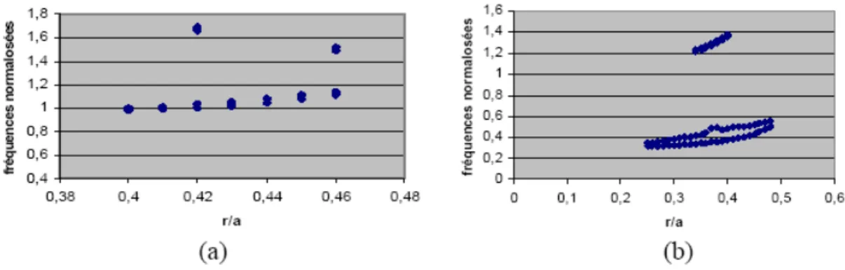
Our goal is to model a microcavity based on bidimensional photonic crystal over GaAs substrate with hexagonal periodicity with height quality factor of resonance at 1550 nm. First we study the photonic band gap width function of r/a ratio (r: holes radius and a: the period) for TE and TM modes. The results are illustrated in Figure 3.
Figure 3. The width of PBG with different values of r/a in TE mode (a) and TM mode (b)
247 Figure 4. (a) 2D photonic crystal model 11 × 7 holes over GaAs substrate r/a=0.4, (b) band
diagram of the structure
Figure 5. (a) the 1550 nm mode, (b) the density of 1550 nm mode.
(a) (b)
(a)
248 On the PBG diagram we have on standard frequency a/ . We calculate the radius and the period to obtain the wavelength 1550 nm on the middle of the PBG. To obtain a resonance and height quality factor Q in the default for this wavelength.
(23) (24) The density of mode showed in figure 5.a (DOM) is an indicator about light conservation by the cavity. We calculate the quality factor Q in equation 20 and we represent the resonant mode in the photonic crystal structure in figure 5.b:
45 (25)
In the next section, we study a microdisk microcavity model, to compare it with photonic crystal cavity, and we will choose the structure with height quality factor Q.
3.2 Mocrodisk model
Microdisk uses TIR both for z-direction and in-plane direction confinement. Light is circulating around the disk as whisperling gallery modes (WGM) [13, 14, 15, 16]. Much of the laser characteristics [17, 18, 19, 20, 21, 22, 23], and cavity QED applications [24, 25] were demonstrated. Since microdisk is a traveling wave resonator, it is possible to couple the light by a waveguide if WGM and waveguide is phase matched. The radiation profile is in the in-plane direction, so that it might be suitable for lateral waveguide coupling and scalability. Microdisks supporting high-Q whispering-gallery resonances were first studied in the context of semiconductor micro lasers in the early 1990s [26]. Since that time there has been extensive work on incorporating self-assembled InAs QD active regions within semiconductor microdisks for studying quantum interactions of light and matter [27]. We can express the harmonic filed hz,q in homogenous layer by the equation 26.
(26)
With the following equation, we will determine an equivalent relationship with the harmonic component e,q in equation 27.
(27)
We can write Hankel derivate in form of equation 28.
(28)
Equation 27 can write with form of equation 29.
(29)
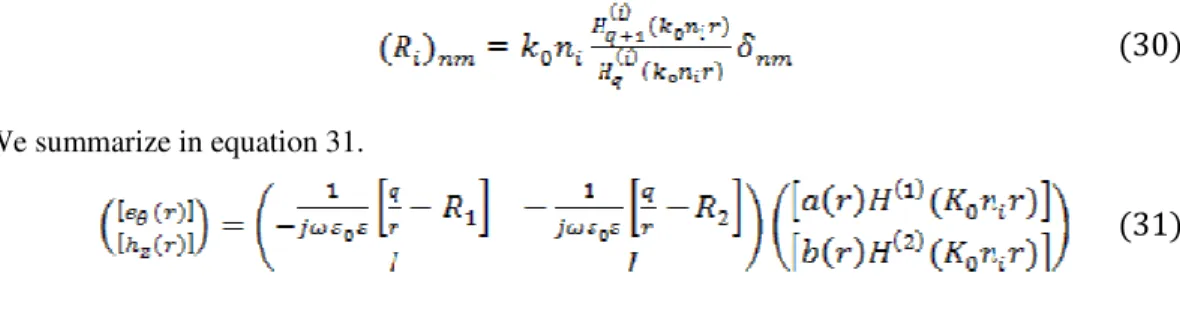
We can write a matrix form introducing Ri matrix with i=1 or i=2, Ri is presented in equation
249
(30)
We summarize in equation 31.
(31)
We obtain transition matrix which allows connecting harmonic to amplitudes. At each interface we can use this matrix to obtain amplitude transition matrix TA(S) rather than harmonic transmission matrix M(S). In our case, we are intressed on the interior interface characterized by homogenous refractive index nint and on the exterior interface characterized by homogenous
refractive index next. The final transition harmonic matrix is MT.
(32)
(33)
(34)
Calculate determinant of TA matrix equal 0 gives resonance complex wavelengths values as solution of this system. We can use on SVD method developed by Andrea. But, Newton Raphson method is ample.
We design a microdisk with r=3,56 µm of GaAs, we vary and we calculate det( (r)).
250 We detect some modes illustrated in figure 6, we are interested by the mode near 1550 nm, to calculate the exactly wavelength of resonant mode we use a Newton-Raphson method. For the described structure we obtain res=15534 nm and Q=7226. The advantage of microdisk structure is the simplicity of the fabrication process, counter to the photonic crystal structure. But with photonic crystal structure we obtain a quality factor Q highest then microdisk structure, the second asset of the first structure is that we have only resonant mode around 1550 nm (figure 5.b) that permit to eliminate other non resonant photons and it increases the probability to obtain a single photon emitted.
4.
C
ONCLUSIONSIn this paper we are interested in studying a announced single photon source model, it consists on pyramidal quantum dot conception based on effective mass model, to calculate the photons energies emitted, the optimum dimensions of pyramid selected to obtain one photon at 1550 nm. We have developed a comparative study between photonic crystal and microdisk microcavities. We remark that the quality factor of photonic crystal microcavity Q= 45 is higher than quality factor of microdisk microcavity Q=7226. The second deduction is with the photonic crystal we have only one mode at 1550 nm but with microdisk structure we have others modes nearly than 1550 nm. These two points indicate that the photonic crystal microcavity is more appropriate to be used with quantum dot to form a announced single photon source. There is other kind of single photon source a heralded single photon source it consists on 2D active photonic crystal to generate photons at 1310 nm and 1550 nm with height coefficient efficiency around 70% of laser photons are converted at 1310 nm and 1550 nm. Where photons at 1310 nm and 1550 nm will be spatially separated; the photon at 1310 nm is the trigger to announce the photon at 1550 nm.
R
EFERENCES[1] C.Benett and al, (1999) “Teleporting an unknown quantum state via dual classical and Einstein-Podolsky-Rosen channels”, Phys Rev, Vol. 70, No. 13, pp 1895-1899.
[2] E. Knill, R. Laflamme and G.J Milburn, (2001) “A scheme for efficient quantum computation with linear optics”, Nature, Vol. 409, pp 46-52.
[3] M.Attia and R.Chatta, (2010) “Photon Pair Generation 1310 – 1550 nm Based on Active Photonic Crystal: Heralded Single Photon Source Model”, International Conference on Transparent Optical Networks ICTON.
[4] J.Y. Marzin, J.M. G¶erard, A. IzraÄel, D. Barrier, and G. Bastard, (1994) “Photoluminescence of Single InAs Quantum Dots Obtained by Self-Organized Growth on GaAs”, Phys Rev, Vol. 73, pp 716.
[5] T. Yoshie, J. Vuckovic, A. Scherer, H. Chen and G. Deppe, (2001) “High quality two-dimensional photonic crystal slab cavities”, Appl Phys, Vol. 79, pp 4289.
[6] T. Yoshie, J. Vuckovic, A. Scherer, H. Chen and G. Deppe, (2001) “High quality two-dimensional photonic crystal slab cavities”, Appl Phys, Vol. 79, pp 4289.
[7] J.-M. Gerard, B. Sermage, B. Gayral, B. Legrand, E. Costard and V. Thierry-Mieg, (1999) “Enhanced Spontaneous Emission by Quantum Boxes in a Monolithic Optical Microcavity”, Phys Rev, Vol. 81, pp 1110.
[8] M.B.Ward, O.Z. Karimov, D.C.Unit et al, (2005) “Telecom wavelength quantum dot single photon source”, Quantum electronics and laser science confererence, Vol. 1, pp 134-136.
[9] T. Hwang, W. Lin, W Chang et al, (2004) “Numerical simulation of three dimensional pyramid quantum dot”, J of Comp phys, pp 208-232.
251 [11] T.F. Krauss, (2003) “Planar photonic crystal waveguide devices for integrated optics”, Phys Rev,
Vol. 197, No. 3, pp 608-702.
[12] R.Hillerand et al, (2000) “Theorical band gaps studies for two-dimensionnel photonic crystals with varying column roundness”, Phys Stat, Vol. (b) 217, pp 981.
[13] S.L McCall, A. F. J. Levi, R. E. Slusher, S. J. Pearton and R. A. Logan, (1992) “Whispering-gallery mode microdisk lasers”, Appl Phys Lett, Vol. 60, pp 289.
[14] Mohideen, W. S. Hobson, S. J. Pearton, F. Ren, and R. E. Slusher, (1994) “GaAs/AlGaAs microdisk lasers”, Appl Phys Lett, Vol. 64, pp 1911.
[15] B. Gayral, J. M. Gerard, A. Lemaitre, C. Dupuis, L. Manin, and J. L. Pelouard, (1999) “High-Q wet-etched GaAs microdisks containing InAs quantum dots”, Appl Phys Lett, Vol. 75, pp 1908.
[16] A. Rastelli, A. Ulhaq, Ch. Deneke, L. Wang, M. Benyoucef, E. Coric, W. Winter, S. Mendach, F. Horton, F. Cavallo, T. Merdzhanova, S. Kiravittaya, and O.G. Schmidt (2006) “Fabrication and characterization of microdisk resonators with In(Ga)As/GaAs quantum dots”, Phys Stat, Vol.(c) 3, pp 3641.
[17] R. E. Slusher, A. F. J. Levi, U. Mohideen, S. L. McCall, S. J. Pearton, and R A. Logan, (1993) “Threshold characteristics of semiconductor microdisk lasers”, Appl Phys Lett, Vol. 63, pp 1310. [18] Mee Koy Chin, Daniel Y. Chu, and Seng-Tiong Ho, (1994) “Estimation of the spontaneous
emission factor for microdisk lasers via the approximation of whispering gallery modes”, J Appl Phys, Vol. 75, pp 3302.
[19] P. Michler, A. Kiraz, Lidong Zhang, C. Becher, E. Hu, and A. Imamoglu, (2000) “Laser emission from quantum dots in microdisk structures”, Appl Phys Lett, Vol. 77, pp 184
[20] H. Cao, J. Y. Xu, W. H. Xiang, Y. Ma, S.-H. Chang, and S. T. Ho, G. S. Solomon, (2000) “Optically pumped InAs quantum dot microdisk lasers”, Appl Phys Lett, Vol. 76, pp 3519.
[21] B. H. Park, J. C. Ahn, J. Bae, J. Y. Kim, M. S. Kim, and S. D. Baek, (2001) “Evanescent and propagating wave characteristics of the photonic quantum ring laser”, Appl Phys Lett, Vol. 79, pp 1593.
[22] W. H. Wang, S. Ghosh, F. M. Mendoza, X. Li, D. D. Awschalom, and N. Samarth, (2005) “Static and dynamic spectroscopy of (Al,Ga)As/GaAs microdisk lasers with interface fluctuation quantum dots”, Phys Rev, Vol. (b) 71, pp 155306.
[23] Z. G. Xie, S. G¨otzinger, W. Fang, H. Cao, and G. S. Solomon, (2007) “Influence of a Single Quantum Dot State on the Characteristics of a Microdisk Laser”, Phys Rev Lett, Vol. 98, pp 117401.
[24] A. Kiraz, P. Michler, C. Becher, B. Gayral, A. Imamoglu, Lidong Zhang, and E. Hu, W. V. Schoenfeld and P. M. Petroff, (2001) “Cavity-quantum electrodynamics using a single InAs quantum dot in a microdisk structure”, Appl Phys Lett, Vol. 78, pp 3932.
[25] P. Michler, A. Kiraz, C. Becher, W. V. Schoenfeld, P. M. Petroff, Lidong Zhang, E. Hu, and A. Imamoglu, (2000) “A Quantum Dot Single-Photon Turnstile Device”, Science, vol. 290, pp 2282. [26] A.F.J. Levi, R.E. Slusher, S.L. McCall, S.J. Pearton, and R.A. Logan, (1993) “Threshold
characteristics of semiconductor microdisk lasers”, Appl Phys, Vol. 63, pp1310–1312.
[27] K.J. Luo, J.Y. Xu, H. Cao, Y. Ma, S.H. Chang, S.T. Ho and G.S. Solomon, (2001) “Ultrafast dynamics of InAs/GaAs quantum-dot microdisk lasers”, Appl Phys, Vol. 78, pp 3397-3399.
Authors
252 Tunisia. Since February 2007, he has been working as a lecturer at INSAT. He is currently a PhD candidate at SUP’COM and affiliated with the Green and Smart Communication Systems (GRES’COM) Laboratory at SUP’COM, where he is conducting research in the area of optical networking.