Dissertação de Mestrado
Metallurgical characteristics of Samarco Mineração’s product portfolio and their influences on Western European blast furnace operations
Autor: Plínio Gomes Bueno
Orientador: Professor Luiz Fernando Andrade de Castro
Plinio Gomes Bueno
Metallurgical characteristics of Samarco Mineração’s product portfolio and their influences on Western European blast furnace operations
Dissertação de mestrado apresentada ao
Programa de Pós-Graduação em
Engenharia Metalúrgica, Materiais e de Minas da Escola de Engenharia da Universidade Federal de Minas Gerais, como requisito parcial para obtenção do Grau de Mestre em Engenharia Metalúrgica, Materiais e de Minas.
Área de Concentração: Metalurgia Extrativa Orientador: Professor Luiz Fernando Andrade de Castro
Belo Horizonte
Universidade Federal de Minas Gerais Escola de Engenharia
Bueno, Plínio Gomes.
B928m Metallurgical characteristics of Samarco Mineração’s product portfolio and their influences on Western European blast furnace operations [manuscrito] / Plínio Gomes Bueno. - 2015.
xvi, 122 f., enc.: il.
Orientador: Luiz Fernando Andrade de Castro.
Dissertação (mestrado) - Universidade Federal de Minas Gerais, Escola de Engenharia.
Bibliografia: f.118-122.
1. Engenharia metalúrgica - Teses. 2. Metalurgia extrativa - Teses. 3. Altos-fornos - Teses. I. Castro, Luiz Fernando Andrade de. II.
Universidade Federal de Minas Gerais. Escola de Engenharia. III. Título.
The author would like to thank the various stakeholders who contributed to this dissertation:
Helio Cardoso and Mauricio Otaviano for their coaching lessons on technical, professional and personal levels.
My senior managers Roberto Carvalho, Leonardo Sarlo and Erik Scholten who believed and supported my plan of achieving a master degree next to the challenging work agenda at Samarco Netherlands.
The technical support team of Samarco comprised of Flavio Lopes, Vicente Campanharo, Francisco Pinheiro, Philippe Rocha, Maciel Bianchi, Ana Maria Guilherme, Rafael Camelo and Welter Santos.
Samarco’s Process Engineering staff for the test work and analyses, especially Heidy Simões, Thiago Marchezi, Vinicius Perin and Alaecio Meschiatti.
My colleagues at Samarco Iron Ore B.V. Wellington Ceciliano, Douwe Bergsma, Samantha Maldonado and Shirley Elwards for their patience and support.
Dr. Volker Ritz from Studiengesellschaft fuer Eisenerzaufbereitung (SGA), for the metallurgy lessons and great collaborative work.
Summary
1. Introduction ...1
2. Objectives ...3
3. Literature review ...4
3.1. The importance of steel to society, contextualization of traded volumes and deployment to the seaborne pellets requirement...4
3.2. A brief history of ironmaking ...8
3.3. Contextualization of modern blast furnace operations ... 10
3.3.1. Thermodynamics ... 11
3.3.1.1. Indirect reduction of iron ores ... 11
3.3.1.2. Direct reduction of iron ores ... 14
3.3.2. Kinetics... 16
3.4. Metallurgical influence of ferrous burden in a blast furnace operation ... 18
3.5. Granular zone ... 19
3.5.1 Degradation during reduction at low temperatures ... 21
3.5.2. Reducibility ... 22
3.5.3. Swelling ... 23
3.6. Cohesive (softening and melting) zone ... 25
3.7. Dripping zone ... 27
3.8. Raceway ... 28
3.9. Hearth ... 28
4. Materials and methods ... 28
4.1. Pellet production in a pilot scale ... 28
4.1.1. Pressure grinding - roller press ... 31
4.1.2. Pilot mixing ... 32
4.1.3. Pilot disc ... 33
4.1.4.1. Preparation of green pellets for induration in the pot grate ... 36
4.1.4.2. Induration of green pellets in the pot grate ... 37
4.2. Chemical characterization of pellets ... 39
4.3. Physical characterization of pellets ... 39
4.3.1. Determination of crushing strength ... 39
4.3.2. Determination of the tumble and abrasion indices ... 40
4.4. Metallurgical testing methodologies for pellets ... 41
4.4.1 Dynamic test for low-temperature reduction-disintegration ... 41
4.4.2. Determination of relative reducibility ... 42
4.4.3. Determination of relative free-swelling index ... 42
4.4.4. Determination of reduction under load ... 43
4.5. Sinter production in a Pilot Scale ... 44
4.5.1. Apparatuses utilized in the pilot sintering plant ... 47
4.5.2. Process description ... 48
4.6. Metallurgical testing of pellets, sinter and their mixtures through the softening and melting apparatus (REAS) ... 50
4.7. Microscopy characterization ... 55
5. Results and discussions ... 56
5.1 Chemical and physical characteristics of Samarco pellets and typical West European Sinter ... 56
5.2 Microstructure of oxide pellets ... 59
5.2.1 PBFMB45 ... 59
5.2.2 PBFSTD ... 63
5.2.3 PBFHB ... 65
5.2.4 Summary of macroscopic differences of Samarco’s three blast furnace pellet types ... 67
5.3 Metallurgical characteristics of pellets in a blast furnace’s granular zone ... 69
5.3.1 Low Temperature Disintegration ... 69
5.3.3 Reduction under load ... 74
5.3.4 Reducibility ... 79
5.4 Metallurgical characteristics of pellet-sinter mixes in the cohesive zone... 83
5.4.1 Main differences of pellets and Standard EU sinter under microscopy ... 83
5.4.2 Morphological differences between the components of pellets and Sinter ... 85
5.4.2.1 Hematite ... 85
5.4.2.2 Magnetite ... 86
5.4.2.3 Silicates ... 87
5.4.2.4 Ferrites ... 87
5.4.2.4 Porosity ... 88
5.4.3 REAS Test Results ... 89
5.4.3.1 Reduction behavior during indirect and direct reduction phases ... 90
5.4.3.2 Softening and melting behavior ... 103
6. Conclusions ... 113
LIST OF FIGURES
Figure 1: Production of steel versus other metals and competitor materials in 1970 and
2013(3). ...4
Figure 2: Crude steel production through BOF and EAF routes(4). ...5
Figure 3: Crude steel production through BOF route per region(4). ...6
Figure 4: Crude steel production through EAF route per region(4). ...6
Figure 5: Hot metal production per region(4). ...7
Figure 6: Pellet rates in blast furnaces in 2014(4). ...7
Figure 7: Global consumption of seaborne pellets in 2014(4). ...8
Figure 8: Steelmaking historical evolution(3). ...9
Figure 9: Maturity curve of available technologies for the production of primary iron(6).10 Figure 10: Iron – oxygen – carbon diagram. ... 13
Figure 11: Iron – oxygen – hydrogen diagram. ... 13
Figure 12: Iron – oxygen – carbon – hydrogen diagram. ... 14
Figure 13: Schematic view of direct and indirect reduction areas in a blast furnace(7). . 16
Figure 14: Different micro and macro porosities in iron ore pellets produced out of different ore minerals(11). ... 17
Figure 15: Topo-chemical reaction model for iron ore agglomerates. ... 18
Figure 16: Hierarchical levels in a blast furnace and their relationship(12). ... 18
Figure 17: Typical zone division of a blast furnace and metallurgical testing standards applied in this study. ... 19
Figure 18: Influence of particles’ size distribution in burden permeability(16). ... 20
Figure 19: Burghard diagram for swelling and Delta P as function of silica content and basicity. ... 24
Figure 20: Influence of quaternary basicity in swelling index. ... 24
Figure 21: XRF apparatus for chemical characterization of raw materials. ... 29
Figure 22: Optical microscopy apparatus. ... 30
Figure 23: Samarco’s pilot roller press. ... 31
Figure 24: Change in size distribution of Samarco’s pellet feed when subject to the pilot roller press(42). ... 32
Figure 4.5: Change in the aspect of the iron ore particle’s size through SEM analysis.32 Figure 26: Samarco’s batch-type pilot mixer. ... 33
Figure 27: Schematic view of green pellet formation. ... 34
Figure 29: Schematic view of the pot grate furnace. ... 35
Figure 30: Pot grate apparatus. ... 36
Figure 31: Temperature profile of the pellet pot layers during induration test of PBFMB45. ... 38
Figure 32: Temperature profile of the pellet pot layers during induration test of PBFSTD. ... 38
Figure 33: Temperature profile of the pellet pot layers during induration test of PBFHB. ... 38
Figure 34: Plasma – ICP/OES apparatus. ... 39
Figure 35: Cold compression strength testing apparatus. ... 40
Figure 36: Tumble drum testing apparatus. ... 40
Figure 37: Low-temperature disintegration testing apparatus at Samarco’s metallurgical laboratory. ... 41
Figure 38: Reducibility testing apparatus at Samarco’s metallurgical laboratory. ... 42
Figure 39: Swelling testing apparatus at Samarco Mineração’s metallurgical laboratory. ... 43
Figure 40: Schematic view of a sinter pot. ... 47
Figure 41: Sinter pot with ignition hood and pot after ignition. ... 48
Figure 42: Sinter cake before crushing. ... 50
Figure 43: Schematic view of the REAS testing apparatus. ... 53
Figure 44: REAS testing apparatus at SGA. ... 54
Figure 45: Scanning electron microscope at Samarco’s laboratories. ... 55
Figure 46: Cold compression strength of Samarco’s three pellet types in the size range 16 to 12mm. ... 58
Figure 47: Tumble and abrasion indexes of Samarco blast furnace pellets and typical Western European Sinter. ... 59
Figure 48: Embedded pellet samples for microscopy analysis. ... 59
Figure 49: Macrostructure of a crossed section of PBFMB45. ... 60
Figure 50: Microstructure of PBFMB45 at 500x and 1000x magnifications in an optical microscope. ... 61
Figure 51:SEM analysis of PBFMB45 and intra-granular porosity (A) & (B) and semi-reacted silica grain (C). ... 61
Figure 52: Intra-granular porosity and bridge-bonding of PBFMB45. ... 62
Figure 54: Microstructure of PBFSTD at 500x and 1000x magnifications in an optical
microscope. ... 63
Figure 55: Distribution of silicates and pores, as well as bridge-bonding of PBFSTD. . 64
Figure 56: Macrostructure of a crossed section of PBFHB. ... 65
Figure 57: Microstructure of PBFHB at 500x and 1000x magnifications in an optical microscope. ... 65
Figure 58: Distribution of silicates and pores, as well as bridge-bonding of PBFHB... 66
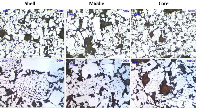
Figure 59: Shell, middle and core sections of Samarco’s three pellet types at 1000x magnification. ... 67
Figure 60: Inter-granular porosity through image analysis. ... 68
Figure 61: Grain area quantification through image analysis. ... 68
Figure 62: Grain quantification through image analysis. ... 69
Figure 63: Comparison of the LTD test and an industrial blast furnace operation in relation to CO partial pressure and temperature on an iron-oxygen-carbon diagram. .. 70
Figure 64: Difference of grain morphologies, porosity and percentage of silicates in the three blast furnace pellet samples at 1000x magnification. ... 71
Figure 65: Quantitative assessment of the presence of silicates and ferrites in the three blast furnace pellet samples through 2-D image analysis. ... 71
Figure 66: ISO low-temperature reduction degradation result. Percentage of pellets above 6.3mm. ... 72
Figure 67: ISO low-temperature reduction degradation result. Percentage of pellets above below 0.5mm. ... 72
Figure 68: Examples of whisker formations in Samarco pellet samples. ... 73
Figure 69: Comparison of the swelling test and an industrial blast furnace operation in relation to CO partial pressure and temperature on an iron-oxygen-carbon diagram. .. 73
Figure 70: Swelling index of Samarco’s three blast furnace pellet types. ... 74
Figure 71: Comparison of the swelling test and an industrial blast furnace operation in relation to CO partial pressure and temperature on an iron-oxygen-carbon diagram. .. 75
Figure 72: Bed height contraction and pressure differential of Samarco’s blast furnace pellets. ... 76
Figure 73: Reduction degree and bed height contraction of Samarco’s blast furnace pellets. ... 77
Figure 93: Reduction index of PBFMB45 and typical Western European sinter
separately as well as their mixtures at 20%/80% and 40%/60% ... 92
Figure 94: Reduction index of PBFSTD and typical Western European sinter separately as well as their mixtures at 20%/80% and 40%/60%. ... 93
Figure 95: Reduction index of PBFHB and typical Western European Sinter separately as well as their mixtures at 20%/80% and 40%/60%. ... 94
Figure 96: Pressure differential until 150 minutes of the REAS test of PBFBM45, PBFSTD and PBFHB. ... 95
Figure 97: Reduction index at reference points during indirect reduction of Samarco pellets, typical Western European sinter and their mixtures. ... 96
Figure 98: Reducibility R of burden Samarco pellets and typical Western European sinter tested separately. ... 97
Figure 99: Reducibility R of PBFMB45 and typical Western European Sinter. ... 98
Figure 100: Reducibility R of PBFSTD and typical Western European sinter. ... 99
Figure 101: Reducibility R of PBFHB and typical Western European sinter. ... 100
Figure 102: CO reference points for Samarco pellets and typical Western European sinter. ... 102
Figure 103: Reduction index at reference points (indirect reduction and end of test) of Samarco pellets, typical Western European sinter and their mixtures. ... 103
Figure 104: Softening temperature (shrinckage 50%) of Samarco pellets and typical Western European Sinter ... 104
Figure 105: Softening temperature (differential pressure = 200 mmWG) of Samarco pellets and typical Western European Sinter ... 105
Figure 106: temperature at 50% shrinkage and temperature at dp maximum (200mmWG) of Samarco pellets, typical Western European sinter and their mixtures. ... 106
Figure 107: Fe-C binary diagram and the influence of carburization in the reduction of the solidus temperature. ... 107
Figure 108: CaO-FeO-SiO2 ternary diagram. ... 108
Figure 109: Melting and dripping temperatures of PBFMB45. ... 109
Figure 110: Melting and dripping temperatures of PBFSTD. ... 109
Figure 111: Melting and dripping temperatures of PBFHB. ... 110
LIST OF TABLES:
Table I – 3 Reducibility of synthetic mineral components of a sinter 22 Table I – 4 Characterization of raw materials for pellet production 30 Table II – 4 Mineralogical characterization of Samarco’s pellet feed through
optical microscopy
30
Table III – 4 Percentage of mixed intakes on a dry basis 33 Table IV – 4 Mix of sinter feed and BF returned fines utilized for the
production of the typical Western European sinter sample
44
Table V – 4 Quality characteristics of the sinter fines utilized for the production of the typical Western European sinter sample
45
Table VI – 4 Quality characteristics of the raw materials utilized for the production of the typical Western European sinter sample
46
Table VII – 4 Sinter pot overall design and process characteristics 47 Table VIII – 4 Process characteristics during pilot production of the typical
Western European Sinter sample
49
Table IX – 4 Data recorded through the conduction of the REAS softening and melting test
53
Table X – 4 Design of experiment for the REAS test 55 Table I – 5 Chemical characterization of Samarco blast furnace pellets and
typical Western European Sinter
57
LIST OF ANNOTATIONS:
∆P Pressure differential between the inlet and outlet of a solid burden being percolated by a gas flow, Pa;
H Extension of the solid burden, m; µ Viscosity of gas, poise;
ε Void fractions in a burden, adimensional;
v0 Velocity of gas inlet, m/s;
ρ Specific mass of gas kg/m3;
ψ Sphericity of the solid particles, adimensional;
dp Diameter of the particles in the burden, m.
Abstract
Western European Blast Furnaces have been increasing the participation of pellets in their burden in substitution of sinter and lump ores through time. The hot metal production process as a whole is therefore becoming more subject to the quality characteristics of this ferrous agglomerate. This study provides a comprehensive evaluation of the metallurgical characteristics of three low-slag pellets from Samarco Mineração’s blast furnace portfolio which differ significantly in binary basicity (CaO/SiO2). As to assess the influence of these pellets in the behavior of a blast furnace’s granular zone, low temperature disintegration, reducibility and swelling tests were carried out. As to understand the behavior of the subject pellets in the cohesive zone of a blast furnace, reduction under load tests and rounds of softening and melting tests with individual pellet types and their combination with a typical Western European sinter were made in partnership with Studiengesellschaft Für Eisenerzaufbereitung (SGA).
Pellets and sinter samples have been produced in pilot plants of Samarco Mineração and SGA, respectively. Metallurgical results point at low degradation during reduction for all pellet types and relative higher reducibility of pellets, especially the fluxed types when compared to sinter. Different swelling, softening, melting and dripping temperatures of pellets are closely associated to their reduction degree, slag content, basicity and microstructural characteristics. The microstructures of oxide pellets with different basicities significantly change in relation to grain sizes, coalescence and recrystallization levels.
When mixtures of pellets and typical Western European Sinter are subject to the REAS methodology, a strong interaction between the agglomerate types is noticed, promoting changes in the overall softening, melting and dripping behavior of the bulk.
Key Words
Resumo
Altos-Fornos do oeste europeu tem aumentado a participação de pelotas em seus leitos em substituição ao sinter e granulado através dos tempos. A produção de gusa está, desta maneira, se tornando mais dependente das características de qualidade deste aglomerado de ferro. Este estudo fornece uma avaliação completa das características metalúrgicas de três pelotas de baixa escória do portfólio de produtos da Samarco Mineração, que diferem significativamente em basicidade binária (CaO/SiO2). Para medir a influencia destas pelotas no comportamento da zona granular de um Alto-Forno, testes de degradação à baixa temperatura, redutibilidade e inchamento foram realizados. Para entendimento do comportamento destas pelotas na zona coesiva de um Alto-Forno, testes de redução sob-pressão e amolecimento fusão em pelotas e misturas de pelotas com um sínter típico do oeste europeu foram feitos em parceria com o laboratório alemão Studiengesellschaft Für Eisenerzaufbereitung (SGA).
As amostras de pelotas e sínter foram produzidas nas plantas piloto da Samarco Mineração e SGA, respectivamente. Resultados metalúrgicos apontam baixa degradação sob-redução em todas as pelotas e relativamente maior redutibilidade de pelotas, especialmente as fluxantes, quando comparadas ao sínter. Diferentes níveis de inchamento, temperaturas de amolecimento, fusão e gotejamento de pelotas estão bastante associados aos seus graus de redução, níveis de escória, basicidade e suas características microestruturais. As microestruturas de pelotas com diferentes basicidades variam significativamente em termos de tamanho de grão e níveis de coalescimento e recristalização.
Quando misturas de pelotas e sínter típico do oeste europeu são submetidas à metodologia REAS, uma forte interação do leito é notada, promovendo mudanças em seu comportamento geral de amolecimento, fusão e gotejamento.
Palavras-chave
1. Introduction
Iron ores and their different forms have been changing in quality characteristics and availability throughout time. This fact has caused integrated steel mills to adapt themselves on the way they process this raw material. European plants significantly changed their operating standards when migrating from mostly domestic iron ore sources to the seaborne market in the second half of the 20th century. Throughout this period blast furnaces grew in size and efficiency and had their number significantly decreased. Many steel works sought access to the Atlantic Ocean where availability of high grade iron ore production had been on the rise, especially in Brazil. With the advancements of sintering technology, most plants were in this period of time running mainly on sinter and lump ore for the production of hot metal. Later in time, factors like environmental constraints, the decrease of quality of natural sinter feed and lump ore and the increase of iron ore concentrates for pelletizing, led to the partial replacement of other ferrous sources by pellets as direct charge in Western European Blast Furnaces.
Hot metal production in the EU 15 member countries (blast furnace operating countries in Europe which are organized in the European Blast Furnace Committee) had fluctuated from 89 to 96 million tons per year between 1990 and 2007, while the number of active blast furnaces decreased from 92 to 57. After the slump in production caused by the economic crisis of 2008 and 2009, the industry in this region has partially recovered to a hot metal production of 75.9 million tons in 2013 with 45 active blast furnaces(1). In 1990 European Blast furnaces were operated at sinter rates of 80% whereas nowadays pellet rates of 30 to 45% are common, especially because cost reduction strategies have caused major players to concentrate production in best performing reactors. As the most extreme scenario, Swedish and Finnish blast furnaces run at around 90% pellet, 10% briquette rates, having completely eliminated sinter plant operations. High grade iron ore pellets therefore contribute to process stability and productivity by influencing important blast furnace process KPIs such as slag, coke and PCI rates.
to understand the technical aspects of its products and how they fit the process conditions of West European blast furnaces, not only in relation to physical and chemical qualities but also metallurgical consistency, especially when combined with typical sinters from the region.
2. Objectives
3. Literature review
3.1. The importance of steel to society, contextualization of traded volumes and deployment to the seaborne pellets requirement.
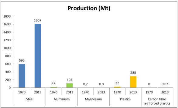
Steel is an extremely versatile metal in terms of ranging properties, applications and recycling capacity. It can be considered the most important existing metal and is almost omnipresent in one’s daily life(1,2,3). Steel represents roughly 90% of the total amount of metals utilized globally. There are altogether about 2,400 grades of steel, 1,500 of which are classified as special steels in the Register of European Steels(3). Figure 1 depicts the difference in production scale of steel compared to other metals and alternative materials in 1970 and 2013.
Figure 1: Production of steel versus other metals and competitor materials in 1970 and 2013(3).
mix of these ferrous sources. BOF and EAF production accounted for about 83% and 27% of the world’s steel output in 2014, respectively.
China has its steel production based on integrated mills, being the biggest BOF producer globally, with over 730 million tons as output in 2014. A distinct example comes from North America, where EAF production corresponds to the largest output of the country’s crude steel, due to reasons like shorter recycling cycle of steel triggered by consumption patterns and, more recently, due to the revitalization of natural gas availability for DRI production. EAF production in North America corresponded to over 71 million tons of output in 2014. Figures 2, 3 and 4 illustrate the breakdown of BOF/EAF contribution to crude steel production globally and the volumes produced by these routes in each geographical location.
Figure 3: Crude steel production through BOF route per region(4).
Figure 4: Crude steel production through EAF route per region(4).
virtually all associated to integrated BOF based steel mills. For the production of hot metal mostly three ferrous burden components are utilized: pellets, sinter and lump ores. Pellets and the European consumption of this raw material are the subject matter of this dissertation; therefore it is of interest to categorize the size of this market for understanding the relevance of the present study. Figures 5 and 6 depict the global hot metal output per year, and the pellet rates of blast furnaces per region.
Figure 5:Hot metal production per region(4).
Although North America and CIS have on average more pellet participation in blast furnace burdens, they typically do not rely on the seaborne pellet trade whereas Europe is very dependent on the ore shipments through the Atlantic Ocean route. The European continent is the largest destination of pellet shipments on the globe, as depicted in figure 7.
Figure 7: Global consumption of seaborne pellets in 2014(4).
Samarco Mineração operates entirely on the seaborne market with an export capacity of 30.5 million tons per year of pellets to all regions. Therefore, understanding the quality requirements of clients situated in the largest consuming market for pellets is a company’s necessity which justifies the present academic study.
3.2. A brief history of ironmaking
the air blast (through man power or water wheels). Finally, the continuous improvement led to further increase in heights and continuous flow of hot metal gave start to the blast furnace era. The first blast furnace is believed to have been developed in the banks of Rhine River in Marches Les Dames, Belgium, around 1340.
Due to environmental pressures in the United Kingdom over deforestation for the production of charcoal, mineral coals started being used for ironmaking in 1700. However, the use of mineral coals largely grew in importance only in 1707 with the development of the coking process. The first hot metal purely based on coke was produced in 1709(5). Coke is able to support much higher static pressure in a blast furnace stack when compared to charcoal and it enabled further increases in heights for more production capacity.
Refining technologies also progressed through time, always with the objective of more capacity and lower cost in steel production. The most relevant evolution steps in hot metal, steel, refining, casting and rolling technologies, are all depicted in figure 8. It is important to mention that the major drivers for a steeper steel production curve in the XX and XXI centuries are the industrial revolution and the rise of China as major global steel manufacturer, respectively.
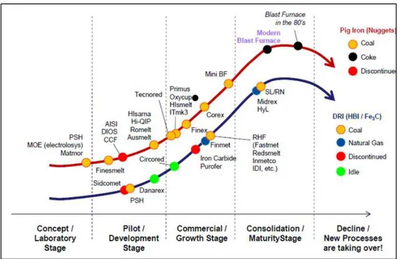
More recently in time, new technologies have been arising for the production of primary iron either in the form of hot metal, iron nuggets, DRI or HBI. As a matter of fact, although other processes are technically and commercially viable, the blast furnaces have been modernized and adapted to today’s requirements of extremely high productivity at large scale and low production costs. Figure 9 depicts an assessment of the maturity state of technologies available for the production of primary iron(6). The blast furnace, although once considered to be under threat by other technologies, is today and for the foreseeable future the most important technology for the production of primary iron.
Figure 9: Maturity curve of available technologies for the production of primary iron(6).
3.3. Contextualization of modern blast furnace operations
The blast furnace has been described as a countercurrent packet-bed reactor in which reducing gases ascend and reduce descending iron ore particles(7). It is a continuously operating shaft furnace which chemically reduces and physically converts iron oxides into liquid iron called “hot metal”(2,8).
technology, basic concepts of thermodynamics and kinetics are required before the core of the study is unfolded.
3.3.1. Thermodynamics
Considering the whole blast furnace as a system, reduction of iron ore takes place through the use of reductants (C, CO and H2). The reducing agents tie oxygen by own oxidation therefore extracting it from the ores. Reduction however is only possible when oxygen potential of the admitted material is smaller than that of the iron oxide. This is determined by the partial pressure of oxygen and by the temperature. The reduction takes place in stages towards oxides with lower oxygen content and finally to metallic Fe.
Traditionally, reduction reactions in a blast furnace are divided into two parts:
- Indirect reduction: takes place through CO and H2 gases at thermodynamic conditions that allow the presence of CO2 and H2O as final products.
- Direct reduction: takes place mostly through reduction by CO and H2 gases in direct presence of carbon at thermodynamic conditions which favor the regeneration of H2O and CO2 into CO as final product(2,7,8,9).
3.3.1.1. Indirect reduction of iron ores
The indirect reduction takes place as the ferrous burden descends in the shaft. Temperature ranges of the reduction steps are roughly 500oC for the conversion of hematite (Fe2O3) to magnetite (Fe3O4), 600 to 900oC for the conversion of magnetite to wüstite (FeO) and further reduction to metallic Fe takes place above 900oC.
3Fe2O3(s) + CO(g) 2Fe3O4(s) + CO2(g) + 52.85 kJ (3.1)
3Fe2O3(s) + H2(g) 2Fe3O4(s) + H2O(g) + 4.86 kJ (3.2)
Fe3O4(s) + m CO(g) 3FeO(s) + CO2(g) + (m-1) CO(g) - 36.46 kJ (3.3)
Fe3O4(s) + n H2(g) 3FeO(s) + H2O(g) + (n-1) H2(g) - 84.45 kJ (3.4)
FeO(s) + p CO(g) Fe(s) + CO2(g) + (p-1) CO(g) + 17.13 kJ (3.5)
FeO(s) + q H2(g) Fe(s) + H2O(g) + (q-1) H2(g) -30.86kJ (3.6)
It has to be mentioned that p > m and q > n, due to the higher CO/CO2 ratio requirement for the reduction of wustite. On an industrial operation, the blast furnace tall design copes with this concept: the lower in the stack, the higher is the CO partial pressure to help with shifting the equilibrium towards the right. A resumed version of the indirect reduction equations is presented below:
Fe2O3(s) + 3CO(g) 2Fe(s) + 3CO2(g) +27.52 kJ (3.7)
Fe2O3(s) + 3 H2(g) 2Fe(s) + 3H2O(g) -88.44 kJ (3.8)
The first versions of iron – oxygen – carbon and iron – oxygen – hydrogen diagrams are depicted in figures 10 and 11. The corresponding equilibrium conditions to the reactions presented above are represented by lines as follows: (3.1) and (3.2) closely follow the x axis, (3.3) and (3.4) equals to (A) and (A’), (3.5) and (3.6) equals to (B) and (B’).
CO2(g) + C(s) 2CO(g) -172.47 kJ (3.9)
Figure 10: Iron – oxygen – carbon diagram.
As a gaseous mixture of H, H2, CO and CO2 is present in the indirect reduction, the “ηH/C” aims at expressing the relationship between partial pressures by the following equation:
ηH/C =
2 2 2
%CO
%CO
O
%H
%H
+
+
(3.9)The curve in the new diagram Fe-C-H-O is changed when ηH/C is altered. Overall it can be noticed that H2 is a stronger reductant than CO, however its higher participation (ηH/C towards zero) would lead to higher energy requirements for the reduction process, as depicted in figure 12.
Figure 12: Iron – oxygen – carbon – hydrogen diagram.
3.3.1.2. Direct reduction of iron ores
The below reactions describe the final state of reduction process:
3Fe2O3(s) + C(s) 2Fe3O4(s) + CO(g) - 119.62 kJ (3.10)
Fe3O4(s) + C(s) 3FeO(s) + CO(g) - 208.93 kJ (3.11)
In blast furnaces direct reduction of solid iron oxides by coke and coal char is negligible. Direct reduction of oxides in primary slag by coke is limited but present. Iron oxides react with carbon monoxide as detailed in reactions 3.1, 3.3 and 3.5, however at temperatures higher than the 950oC to 1000oC range, the carbon dioxide will react with carbon through the Boudouard reaction. Direct reduction can therefore be explained by the total reactions below for both carbon and hydrogen as reductants:
FeO(s) + CO(g) Fe(s) + CO2(g) + 17.3 kJ (3.13) CO2(g) + C(s) 2CO(g) - 172.47 kJ (3.14) FeO(s) + C(s) Fe(s) + CO(g) - 155.34 kJ (3.15)
FeO(s) + H2(g) Fe(s) + H2O(g) - 30.86 kJ (3.16) H2O(g) + C(s) H2(g) + CO(g) - 124.48 kJ (3.17) FeO(s) + C(s) FeO(s) + CO(g) - 155.34 kJ (3.18)
Due to the higher energy requirements of the direct reduction against the indirect reduction, blast furnace operators must enhance the indirect reduction in the granular zone as to achieve lower coke + PCI rates(2,8).
Figure 13: Schematic view of direct and indirect reduction areas in a blast furnace(7).
3.3.2. Kinetics
For the reduction in the solid state, three steps are categorized:
1. Transport phenomena of the reducing gases (H2 and CO) to the solid oxide and oxidized gases (H2O and CO2) are transported out from the reaction front.
2. The reduction reaction itself proceeds essentially at the phase boundary between solid oxide and gas.
3. As a result of the removal of oxygen from the surface of the solid phases and the accompanying transport phenomena, new solid phases such as lower iron oxides or metallic iron are being formed(2)
Firstly the reducing gas has to overcome an important resistance caused by the outer gas boundary layer. Difference in partial pressures is determinant to the diffusion through the outer gas boundary layer. The thickness of the boundary layer is inversely proportional to mass transfer and changes in flow rate are key drivers for its change.
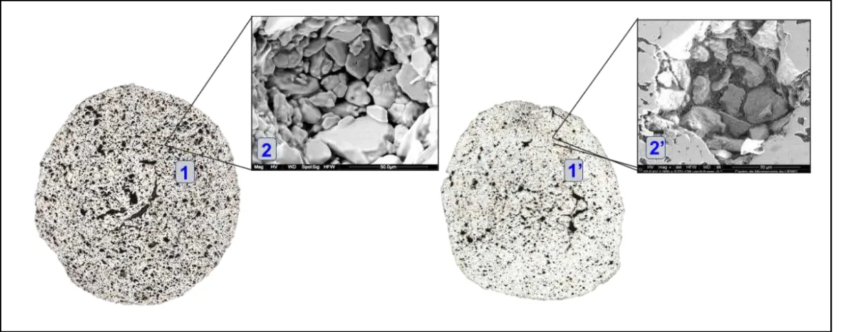
After the gas boundary layer, the second transport mechanism is the gaseous diffusion into macro and micro-pores of an iron oxide. Macro (or intergranular) porosity relates to the voids in between iron ore grains whereas micro (or intergranular) porosity relates to the voids within each iron ore grain. The more porous the material the higher the reduction kinetics is and this is highly correlated to the geological characteristics or iron ores. Figure 14 illustrates the different porosity levels in both macro and microscopic views of two iron ore pellets derived from ores with different mineralogy.
Reduction from Fe2O3 to metallic Fe takes place through the interfacial reaction or three-phase model, illustrated in figure 15. During the first reduction step from hematite to magnetite the crystal structure changes from hexagonal to face-centered cubic and from magnetite to wustite only the iron/oxygen ration is modified.
Figure 15: Topo-chemical reaction model for iron ore agglomerates.
3.4. Metallurgical influence of ferrous burden in a blast furnace operation
The blast furnace can be perceived as a dynamic system which consists of a set of inter-related hierarchical entities. Lower hierarchical entities influence and are influenced by higher hierarchical entities(12). An example of the hierarchical levels and their relationship is depicted in figure 16, where the lower hierarchical entity is the ore’s mineralogy and the higher one is the softening and melting zone and its final influence in the overall behavior of a blast furnace.
On a global furnace level, the burden permeability and charging pattern govern the distribution of gas, as well as heat transfer between gas and solids. However, this global furnace level influences, but is also influenced by the phenomena occurring at the deeper hierarchical level of the burden material.
As to categorize the behavior of iron ore pellets in one typical blast furnace operation, a classical zone division is adopted. Granular and cohesive zones will be the main focus of literature review as they are the subject matter of this dissertation. Dripping zone, raceway and hearth are also of great complexity and importance; however they will be described on a more generalist level. Figure 17 depicts blast furnace zone division and the metallurgical testing standards utilized for assessing the metallurgical behaviors of pellets and sinter in the granular and cohesive zones.
Figure 17: Typical zone division of a blast furnace and metallurgical testing standards applied in this study.
3.5. Granular zone
reduction and the Ergun Equation describes the variables that influence pressure drop across a burden comprised of solid particles. This equation was proposed in the end of the 1940s and shows that two aspects influence delta P, one associated to viscous friction which prevails in the laminar regime and another associated to inertia which prevails in the turbulent regime(13)
3.19
Through an analysis of the equation, the parameters that facilitate better permeability are void fraction, particle’s size and sphericity (for the solid burden components) and lower viscosity, density and speed of gas. Various publications on permeability in a blast furnace stack have been made(12,14,15) and a simple but comprehensive example of the influence of a homogeneous burden size distribution is demonstrated in figure 18.
Figure 18: Influence of particles’ size distribution in burden permeability(16).
The metallurgical phenomena applicable to pellets on a lower hierarchical level which can dictate different behaviors of the granular zone on a higher hierarchical level are related to degradation during reduction, reducibility and swelling.
2 3 2 3 2 ) 0 (v p d ψ ε ε) -(1 1,75ρ ) p d ψ ( ε 0 v ε) -(1 μ 150 H
3.5.1 Degradation during reduction at low temperatures
The major drawback of degradation during low reduction temperatures is related to fines generation, which may partly block voids in the solid burden, hindering the reducing gas passage as suggested in figure 18. Low degradation during reduction must be targeted even knowing that the biggest contributor to pressure drop is located deeper in the reactor in the cohesive zone.
As ferrous burden is fed in a blast furnace, it immediately starts the heat exchange with the upward gases, as described previously on figure 13. After moisture removal and yet at higher zones of the stack, hematite pellets undergo the first stage of reduction at the temperatures that range from 400 to 600oC. The reduction of hematite into magnetite is marked by the structural lattice distortion, accompanied by anisotropic effects. The crystalline transformation from hexagonal hematite to cubic magnetite can generate a volume expansion to an extent of 25%(17,18,19). At relatively low temperatures the single lattice elements cannot move easily and therefore the strain cracks the structure thus destroying the bonding of grains. Cracks are not only observed along the grain boundaries but can also extend inside the grain. The higher the reduction temperature the easier the elements can move and therefore less cracking is found(17).
Degradation during reduction is a phenomenon dependent on the hematite-magnetite conversion rate, residence time at a certain low temperature gradient and most importantly the bonding structure between grains. The bonds formed during the induration process of iron ore pellets can be classified into three groups: iron oxide bonds (bridge bonding), silicate bonds and calcium ferrite/ magnesium ferrite bonds(19,20,21). Hematite bonds are the major responsible for providing pellets the high strength that enables handling, however they lose their stability when subject to reduction, whereas silicate bonds and ferrites tend to keep their structures, softening and melting later during the burden descent. This causes the major difference between the higher degradation at low reduction temperatures of acid pellets compared to fluxed pellets (either by CaO, MgO or a mix of both). The stabilization and reduction of pellets’ degradation by increase of calcium oxide has been proved to work until a certain basicity level. Further increase in basicity will play minor effect on degradation due to the achievement of a cap of structural stabilization(18).
helped pellet suppliers and blast furnace operators to distinguish pellets according to this phenomena.
3.5.2. Reducibility
As described, at the granular zone of a blast furnace the indirect reduction takes place bringing ferrous burden components from their higher oxidation level to wüstite or metallic Fe, until softening temperatures are reached. On the deepest hierarchical level, ore mineralogy and chemistry of slag compounds formed during induration will play a significant role in the kinetics of reduction.
After the oxidizing atmosphere of a pellet induration process the majority of the iron oxide is in the form of hematite and FeO levels are below 1.0%. However, the mineralogy of various pellet feed sources can significantly differ, generating structures that are more or less favorable for reduction. Highly porous minerals like goethite and martite (porous hematite) will generate more reducible structures after induration when compared to specular hematite and magnetite.
The reducibility of different compounds present in one iron ore agglomerate has also been investigated. Results of synthetic mineral components point at the increase of reduction capacity of calcium ferrites with greater number of calcium moles and, on the other hand, to extremely poor reducibility of fayalite (Fe2SiO4) as per table I – 3 (23).
Table I – 3: Reducibility of synthetic mineral components of a sinter(23).
melting points (occurring mostly on acid pellets without CaO or MgO) can impose resistance to reducing gas passage thereby retarding the reaction(18,21).
For iron ore pellets, the ISO 7215 standard for determination of relative reducibility(25) is commonly utilized for quality differentiation.
3.5.3. Swelling
The first stage of reduction, from hematite to magnetite, is characterized by volume expansion and the issues related to this lattice distortion were already highlighted in the discussion over low temperature disintegration. This section will be more deeply focused on the second swelling mechanism characterized by the growth of fibrous iron (whiskers).
The problems of excessive swelling are related to the subsequent degradation or disintegration of the partly-reduced pellets, which may lose stability under the pressure of a compacted burden. This leads to the generation of fines that can hinder the furnace permeability.
Swelling of iron ore pellets occurs during the transformation of wüstite into iron, but like any transformation, this is a balance between iron nucleation and growth of these nuclei(8). Generally the normal swelling (~20%) for the reduced pellets is a very common phenomenon in blast furnaces, but catastrophic swelling may reach over 400% under some conditions(26). Characteristics of pellets (chemical composition, porosity and microstructure), their induration (temperature and time) and reduction conditions (reduction temperature, flow rate) influence the swelling phenomenon(26,27).
- Pellet induration characteristics: homogeneous firing and sufficient energy for the bridge bonding of ore grains are required for low swelling indexes.
- Reduction atmosphere: at H2 atmospheres no abnormal swelling is noticed whereas CO rich atmospheres lead to whisker formation.
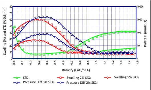
- Chemical composition of pellets: the increase of overall gangue contributes to higher slag formation and reduction of swelling. For the achievement of low-slag pellets without the risk of the catastrophic growth of whiskers during reduction, fluxing agents CaO and MgO contribute to better stability of the agglomerate. Figures 19 (Burghard diagram) and 20 denote the effects of overall slag, binary basicity and MgO contents on swelling.
Figure 19: Burghard diagram for swelling and Delta P as function of silica content and basicity.
ISO has defined one metallurgical standard test for characterization of pellets in relation to their swelling tendency based on volume prior and after reduction conditions that favors the phenomena: ISO 4698 determination of relative free-swelling index(28).
As so far disclosed, permeability in the granular zone is core for smooth blast furnace operations. Another ISO methodology also aims at distinguishing metallurgical property of pellets encompassing aspects of degradation at first steps of reduction, growth of fibrous iron, shrinkage and behavior near softening: ISO 7992 – reduction under load(29).
It is valid to state that no ISO methodology serves the purpose of simulation; however they offer a very good standardized way to differ pellets on their metallurgical behaviors.
3.6. Cohesive (softening and melting) zone
As the ferrous burden continues its descent in the shaft, it will reach softening and melting temperatures. A common approach defines the upper and lower boundaries of the cohesive zone as two isotherms (e.g. 1200 – 1500oC). However, temperature is not an objective criterion for describing the limits of the softening and melting zone. Since the permeability distribution is the aspect of key importance at a global level, it is more obvious to define the boundaries of the softening and melting zone based on this aspect(12). In this zone the metallic burden loses its permeability and gas flow occurs only through the coke layers(30). On a low hierarchical level, the high temperature properties of the ferrous burden largely control the shape, width and position of the cohesive zone. The latter is also affected on a higher hierarchical level by the burden distribution, in particular ore to coke ratio and temperature distribution in the blast furnace. It is important to have the roof of the cohesive zone deep in the blast furnace as to prevent gas flow close to the wall and to minimize coke rate. It is also of great importance to have a thin cohesive zone since it is the major contributor to pressure drop. This can be achieved with smallest gradient of temperatures between the start of softening and end of melting stages(30,31,32).
occur at the same time: the softening and melting of the oxide phase and the softening and melting of the metallic iron phase.
Softening and melting of the oxide phase is extremely influenced by the slag composition and the morphology of the compounds formed. The presence of iron oxide (wustite) also plays a very significant role in the phenomena due to the low liquidus temperature of compounds comprising FeO.
Softening of metal phase is very dependent on the thickness of the metallic shell and its capacity to resist the direct contact with coke particles, which leads to the cementitization phenomena.
If a stepwise description of the softening, melting and dripping of the ferrous burden would be established, the first phenomena to trigger the process would be the melting of the oxide phase with lowest melting point within the agglomerate, which will act as a “lubricant” to the other ore particles. At this stage reduction kinetics is compromised as the liquid slag film imposes difficulty to the transport phenomena of gases. When the burden reaches the cohesive zone of a blast furnace, reduction will already have taken place in a way that a film of metallic Fe around the ore will be present. The metallic Fe film is called metallic shell, which at this moment is the major responsible for confining the mixture of solid and liquid oxides together. The strength of the iron shell will tend to be compromised by effects taking place at both of its extremities. On its internal side the increasing temperatures will lead to higher participation of liquid phases, which tend to penetrate the iron shell as this movement reduces the overall free energy. On its external side the continuous carburization leads to the formation of cementite, which generates cracks in the iron shell structure. The softening will be finally defined when the metallic burden can no longer resist the action of mechanical forces and the iron shell cracks open, promoting the exudation phenomena of liquid phases(12,30).
High MgO bearing pellets at both levels of binary basicity (CaO/SiO2) increase overall softening and melting properties, due to high melting point of slag which keeps the pores open for the reduction to continue(21).
Alumina in the ore lowers the temperature at which primary melt forms in sinter. It would pose difficulties to permeability and continuation of indirect reduction(36).
Softening and melting experiments are not standardized by ISO due to their complexity. They can differ significantly in the ways of accessing the phenomena of a blast furnace cohesive zone. For tests which evaluate a bulk behavior such as the REAS(36) utilized in this dissertation, the interaction between different burden components at high temperatures can be studied(30,31,37,38,39,40,41). Previous studies considering the interaction of acid & basic and acid & MgO fluxed pellets(30,38,39) point at similar softening temperatures, but the same did not apply for dripping and meltdown temperature each of the pellet types individually. The addition of DRI to a mixed burden has the increase of the cohesive zone’s width as an important side effect, however at the same time its blending with pellets/lump ores improves dripping temperature(31,40,41). Burden interaction and melt exudation phenomenon is influenced by the reduction characteristics of pellets, morphology of iron shell, slag distribution, its basicity and viscosity. A mechanism of burden interaction encompasses four steps: sintering of solid phases at interface of pellets, incipient liquid slag formation, interaction of liquid at interface and interaction of core of material(41).
3.7. Dripping zone
3.8. Raceway
The combustion zone (or raceway) is the area where the hot blast containing oxygen is injected through the various tuyeres of a blast furnace. Hot blast at very high speed will generate a semi-void area where most of coke and PCI coal are gasified and oxidized, increasing the temperature to over 2,000oC.
3.9. Hearth
The hearth area comprises the lowest part of the blast furnace. Its main function is the temporary storage of hot metal and slag for controlled timeframes before the tapping process. The dead man extends itself to this zone and it has the important role of sustaining the burden load. At the same time it also has to be permeable for the liquid phases to be drained smoothly through to the tapping hole(s).
4. Materials and methods
As to assess the metallurgical characteristics of Samarco pellets and their interaction with a typical Western European Sinter, an extensive set of laboratory methodologies were used at both Samarco Ponta Ubu – Brazil and SGA, Liebenburg – Germany, which are described in this section.
For an evaluation of only intrinsic properties of Samarco pellets and Western European sinter, it was decided to produce both agglomerates in pilot plants. This decision has helped to eliminate any misleading interpretation of quality results caused by standard deviation from an industrial pellet or sinter plant operation.
4.1. Pellet production in a pilot scale
generation of slag (which is not the major driving force for fired pellets’ resistance, but improves the bridge bonding of pellet feed grains). Anthracite will enhance induration by providing more homogeneous firing of pellets from inside out through its ignition.
Firstly the raw materials to be used as feed mix for pellet production were cautiously sampled and characterized according to their chemical and physical characteristics. An x-ray fluorescence apparatus (XRF) was used for the complete chemical analysis of pellet feed, anthracite, bentonite and limestone. Figure 21 depicts the XRF apparatus at Samarco Mineração.
Figure 21: XRF apparatus for chemical characterization of raw materials.
Table I – 4: Characterization of raw materials for pellet production.
Figure 22: Optical microscopy apparatus.
Table II – 4: Mineralogical characterization of Samarco’s pellet feed through optical microscopy.
Pellet Feed Limestone Anthracite Bentonite
Fe% 66.2 - 4.43
-FeO% 0.47 - -
-SiO2% 1.69 4.78 51.12 59.41
Al2O3% 0.41 0.52 30.17 15.94
CaO% 0.09 49.25 2.9 1.31
MgO% 0.03 3.52 1.5 2.54
P% 0.048 - -
-LOI% 2.93 40.8 -
-Fixed Carbon% - - 71.59
-Volatiles% - - 12.37
-Ash% - - 16.04
-Calorific value (cal/g) - - 6658
+ 100 # 0 11.4 12
- 100 + 200 # 0.4 17.5 17
- 200 + 325 # 2.2 15.8 12.5
- 325# 90 55.3 58.5
95% <200 #
Mineral type Percentage Specular Hematite 51.38%
All characterization results presented good adherence to the usual qualities utilized in industrial scale, therefore the samples were considered suitable for the undertaking of pilot tests.
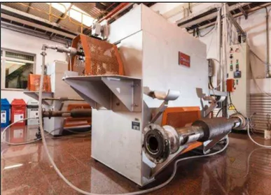
4.1.1. Pressure grinding - roller press
The pilot pressure grinding consists of two counter-rotating rolls mounted in frictionless bearings, enclosed in a frame. Pressure is applied to one of the rolls by means of a hydro-pneumatic spring system, while the other roll is held in a fixed position in the frame. The “free” or “floating” roll is allowed to slide (or float) on frictionless pads, reacting to the forces acting on the roll by the material and the spring system. Feed to the rolls is done through a hopper mounted above them. This apparatus is in line with similarly designed industrial equipment present in between the filtering and mixing stages at each of Samarco’s four pellet plants. Figure 23 depicts the pilot roller press apparatus.
Figure 23: Samarco’s pilot roller press.
Figure 24: Change in size distribution of Samarco’s pellet feed when subject to the pilot roller press(42).
Figure 25: Change in the aspect of the iron ore particle’s size through SEM analysis(42).
4.1.2. Pilot mixing
pellets. Table III – 4 describes the percentage of intakes mixed on a dry basis and figure 26 depicts the pilot mixing equipment.
Table III – 4: Percentage of mixed intakes on a dry basis.
Figure 26: Samarco’s batch-type pilot mixer.
4.1.3. Pilot disc
The balling process will enable the formation of green pellets. At Samarco, iron ore particles must have typically 10.5% moisture for an efficient balling. These particles involved by a water film start touching each other and liquid bridges are formed due to the surface tension of water. Due to the rotating movement of the disc, the union of several water coated particles will take place, generating the first agglomerates. The residence time of the agglomerate in the pelletizing disc enable the liquid bridges to become a network that holds the particles together. Water capillarity and the effective action of bentonite enable the growth of the agglomerate until the desired size distribution. Figure 27 depicts a schematic view of the water surface tension in a green pellet.
Pellet Feed Bentonite Anthracite Limestone
PBFMB45 96.6% 0.4% 1.4% 1.7%
PBFSTD 94.8% 0.4% 1.4% 3.4%
PBFHB 94.1% 0.4% 1.4% 4.1%
On this specific pilot test, balling productivity and final size distribution were not a matter of concern. The standard pot test utilizes a fixed ratio 50% between 16 and 12.5mm and 50% between 12.5 and 9mm and main objective was replicating the quality of fired pellets of Samarco’s portfolio. The disc’s slope, rotating speed, feeding rate and position were chosen to provide the most homogeneous green pellets for the induration stage. Figure 28 depicts Samarco’s pilot balling disc.
Figure 27: Schematic view of green pellet formation.
Figure 28: Samarco’s pilot disc.
4.1.4. Pilot induration machine
Figure 29: Schematic view of the pot grate furnace.
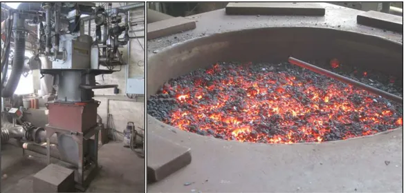
The major components of the pot grate are:
Combustion chamber: where liquefied petroleum gas is ignited for the heating of process gas. The heated airstream is injected in the pot either on updraft or downdraft flows, depending on the stage of induration to be simulated.
Pellet pot: is the recipient where the green pellets are placed for the induration simulation. The Pot has refractory lining and three thermocouples in different height levels for the monitoring of temperature throughout the process.
Wind box: is situated underneath the pot, where occurs the passage of hot air responsible for the updraft drying, cold air responsible for the cooling and the gases deriving from the downdraft drying and firing.
Control system: is a computer system that allows the simulation of residence time of pellets in the drying, firing and cooling zones, as a function of production rhythm and thermal profiles established in each process stage.
Temperature measurement system: is comprised of a set of thermocouples for the measurement of temperatures in all regions of the furnace. The thermocouples T4, T5, T6, T7 and T8 measure the temperatures of hood, burden layers and wind box, respectively.
Control valves: are responsible for adjusting the gas flow for the simulation of the induration process.
Figure 30 depicts Samarco’s pot grate furnace and its peripherals.
Figure 30: Pot grate apparatus.
4.1.4.1. Preparation of green pellets for induration in the pot grate
Hearth layer, with a height of 7cm, is filled in with indurated pellets of 16mm diameter.
A lateral protection layer is also made through the use of pellet screenings (pellet chips) with size distribution from 3.15 to 8mm.
Green pellets produced in the pilot balling disc are classified in two size ranges (50% between 16 and 12.5mm and 50% between 12.5 and 9mm) and homogenized thereafter. The homogeneous mix is placed in the pellet pot.
4.1.4.2. Induration of green pellets in the pot grate
After the preparation of the burden, the green pellets will undergo the induration process according to the defined setup.
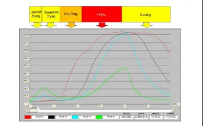
The temperature profile of the superior pellet layer (thermocouple T5), intermediate layer (thermocouple T6), inferior pellet layer (thermocouple T7) and wind box (thermocouple T8) are monitored during induration. Figures 31, 32 and 33 show the actual results during the production of PBFMB45, PBFSTD and PBFHB, respectively.
Figure 31: Temperature profile of the pellet pot layers during induration test of PBFMB45.
Figure 32: Temperature profile of the pellet pot layers during induration test of BFSTD.
4.2. Chemical characterization of pellets
Chemical characterization of the indurated pellets was conducted according to ISO standards. The chemical analysis was made through the use the Plasma ICP/OES apparatus depicted in figure 34.
Figure 34: Plasma – ICP/OES apparatus.
4.3. Physical characterization of pellets
Physical testing methodologies were also utilized for assessing the capacity to endure handling of the three pellet types produced at pilot scale.
4.3.1. Determination of crushing strength
Figure 35: Cold compression strength testing apparatus.
4.3.2. Determination of the tumble and abrasion indices
This standard indicates a method to evaluate the resistance to degradation by impact and abrasion in a rotating drum. It measures the tumble strength and abrasion index of iron ores. A 15kg test portion is placed in a tumble drum and rotated at 25rpm, for a total of 200 revolutions. The product material is screened and the tumble index is expressed as the mass percentage of material greater than 6.3mm, and the abrasion index as the mass percentage of material smaller than 0.5mm. Figure 36 depicts a tumble drum at Samarco’s physical characterization laboratory.
4.4. Metallurgical testing methodologies for pellets
The metallurgical testing standards were conducted for an assessment of the behavior of the three pellet types in the granular and cohesive zones of a blast furnace.
4.4.1 Dynamic test for low-temperature reduction-disintegration
This standard indicates a method to test the disintegration pellets during reduction in a rotation tube at a temperature of 500ºC. In the process, a 0.5kg test portion is heated in a 10rpm rotating tube at a temperature of 500ºC, using reducing gas at a flow rate of 20l/min, consisting of 20% of CO, 20% of CO2, 2% of H2 and 58% of N2 for 60 minutes. Then, the test portion is cooled to a temperature below 100 ºC and screened with test screens of 6.3mm, 3.15mm and 0.5mm. The low-temperature disintegration (LTD) values are calculated as a quantitative measure of the degree of disintegration of an iron ore sample that has been reduced while tumbling: the percentage masses of material greater than 6.3mm, smaller than 3.15mm and smaller than 0.5mm, respectively, are related to the total mass of the test portion after reduction. Figure 37 depicts an LTD testing apparatus at Samarco’s metallurgical laboratory.
4.4.2. Determination of relative reducibility
This standard indicates a method to determine the reducibility in relative terms of pellets. It measures the extent to which oxygen has been removed from iron oxides. In the process, a 0.5kg test portion of iron ore is heated under a flow of inert gas at a rate of 5l/min. When the temperature approaches 900ºC, the flow rate is increased to 15l/min for 30 minutes. The mass of the test portion is measured and the gas is replaced by reducing gas, consisting of 30% of CO and 70% of N2 at a flow rate of 15l/min. After 3 hours, the mass is measured again and nitrogen inserted at a flow rate of 5l/min until the test portion is cooled to 100ºC. The degree of reduction is calculated from the loss in mass and the total iron content of the test portion. Figure 38 depicts a reducibility testing apparatus at Samarco’s metallurgical laboratory.
Figure 38: Reducibility testing apparatus at Samarco’s metallurgical laboratory.
4.4.3. Determination of relative free-swelling index
15l/min and a reducing gas consisting of 30% of CO and 70% of N2, replaces the inert gas at the same flow rate for 60 minutes. After that, the test portion is cooled to a flow rate of 5l/min and the free-swelling index is calculated as percentage, using the difference between the final and initial volumes. Figure 39 depicts a swelling testing apparatus at Samarco’s metallurgical laboratory.
Figure 39: Swelling testing apparatus at Samarco Mineração’s metallurgical laboratory.
4.4.4. Determination of reduction under load
4.5. Sinter production in a Pilot Scale
This study aims at understanding not only the metallurgical behavior of Samarco pellets alone, but also when they are mixed with a typical Western European sinter at proportions usually observed in industrial blast furnaces. For this purpose a representative sample form a typical Western European industrial sinter was reproduced in the pilot plant of SGA in Germany. In this specific case, the blend of ore fines and other intakes, productivity and final quality were all selected according to industrial characteristics of Western European sinter plants. For a typical ore blend in a Western European sinter, ores from Brazil (north and south systems), Canada, Mauritania, as well as BF return fines, were selected in the proportions described in table IV – 4.
Table IV – 4: Mix of sinter feed and BF returned fines utilized for the production of the typical Western European sinter sample.
Similarly to the pellet case, all intakes were fully characterized according to their chemical and physical qualities through ISO standards. Results are presented in tables V – 4 and Table VI – 4.
Ore type Participation in blend
Brazilian Sinter Feed (North System) 40% Brazilian Sinter Feed (South system) 35%
BF Return fines 10%
Canadian Concentrate 8%
Table V – 4: Quality characteristics of the sinter fines utilized for the production of the typical Western European sinter sample.
Designation Braz
il ian si n ter f eed (N o rth Sy s te m ) B raz li an si n ter f eed (So u th Sy s te m ) B F r e tur n f ine s C an ad ian co n cen tr at e M a ur it a nia n C onc e nt ra te Chemical analysis
Fetot [%] 65,32 63,79 56,01 65,64 65,36
FeO [%] 0,20 0,76 7,86 11,26 26,88
SiO2 [%] 2,42 5,47 5,33 4,39 7,26
Al2O3 [%] 1,14 0,78 1,44 0,18 0,55
CaO [%] 0,06 0,34 11,95 0,45 0,41
MgO [%] 0,07 0,17 0,65 0,47 0,55
P [%] 0,016 0,047 0,031 0,006 0,013
S [%] 0,005 0,005 0,032 0,007 0,023
Na2O [%] 0,030 0,004 0,019 <0,005 0,051
K2O [%] 0,025 0,015 0,050 <0,005 0,081
Mn [%] 0,670 0,150 0,460 0,132 0,030
TiO2 [%] 0,056 0,059 0,084 0,036 0,170
V [%] 0,004 0,005 0,005 0,004 0,002
L.O.I [%] 1,82 1,69 0,53 1,64 0,38
Size distribution
+25 mm [%]
+20 mm [%]
+18 mm [%]
+16 mm [%] 1,4 / 1,4
+12.5 mm [%] 5,7 / 5,7 1,0 / 2,4
Table VI – 4: Quality characteristics of the raw materials utilized for the production of the typical Western European sinter sample.
Designation Lim e s tone O liv ine C o ke b reez e B ur nt lim e Chemical analysis
Fetot [%] 0,25 6,25 1,32 0,25
FeO [%] 0,15 5,31 - <0,1
SiO2 [%] 0,96 41,00 6,82 1,79
Al2O3 [%] 0,20 0,61 3,36 0,29
CaO [%] 54,90 0,43 0,95 94,70
MgO [%] 0,50 47,50 0,20 1,16
P [%] 0,003 0,002 0,037 0,005
S [%] 0,020 0,014 0,700 0,052
Na2O [%] 0,010 0,030 0,170 0,060
K2O [%] 0,050 0,045 0,220 0,060
Mn [%] 0,030 0,084 0,007 0,054
TiO2 [%] 0,010 0,013 0,160 0,013
V [%] <0,001 <0,001 0,007 <0,001
L.O.I [%] 43,02 1,34 86,05 1,54
Size distribution
+25 mm [%]
+20 mm [%]
+18 mm [%]
+16 mm [%]
+12.5 mm [%] 0,3 / 0,3
4.5.1. Apparatuses utilized in the pilot sintering plant
Ignition hood: uses a combination of air and natural gas for igniting the top layer of the sinter mix in the sinter pot, enabling the combustion zone to be initiated.
Sinter pot: a refractory lined pot with perforated bottom in which the sinter mix is placed. Gases will be soaked through the bed enabling the sintering process.
Suction chamber & waste gas fan: are responsible for the downdraft suction of gases through the sinter cake, enabling the combustion zone to travel through the sinter pot’s height.
The overall process setups are described in VII – 4. Figure 40 depicts a schematic view of the apparatus.
Table VII – 4: Sinter pot overall design and process characteristics.
Figure 40: Schematic view of a sinter pot.
Pot Grate 450 mm, height 600 mm
Bed Height 520 mm, including 20 mm hearthlayer
Ignition Time 90 seconds
Ignition Temperature 1220 oC
Ignition Suction increasing from 40 to 160 mbar
Sintering Suction 160 mbar
Sintering treatment for return fines generation tumbling (70 revolutions)