Volume No.3, Issue No.5, pp : 351-355 01 May 2014
IJER@2014
Page 351
Numerical Investigation of the Effect of Froude Number on Flow Pattern
around a Single T-shaped Spur Dike in a Bend Channel
M. Vaghefi
1, M. Shakerdargah
2, A. R. Fiouz
3, M. Akbari
4 1Assistant Professor of Hydraulic Structures, Department of Civil Engineering, Persian Gulf University,
Bushehr, Iran.
2
M.Sc. Civil Engineering Department, Islamic Azad University, Bushehr, Iran.
3Assistant Professor of Structures, Department of Civil Engineering, Persian Gulf University, Bushehr, Iran.
3M.Sc. Civil Engineering Department, Persian Gulf University, Bushehr, Iran.
Corresponding Author Email: [email protected]Abstract :
In this paper, flow pattern around anunsubmerged T-shaped spur dike in a 45 degree position, and located in a 90 degree bend with different Froude Numbers has been studied using Flow-3D and has been compared with experimental results. To determine the effect of Froude Number on flow pattern, flow pattern in longitudinal, cross, and plan sections have been studied.
Keywords :
90 Degree Bend, Flow Pattern, T-shaped Spur Dike, Flow-3D, Froude Number.I. Int roduction
Erosion of the banks and bed of natural and manmade channels is a common problem in water resources management. Spur dikes are used in rivers in order to prevent bank erosion. These structures extend from the bank into the streamline, perpendicularly, or at some angle.
Scour around spur dike can cause serious problems, such as weakening structural stability. To better understand why scour occurs around such hydraulic structures, the questions of what the flow distributions around these structures are and how the flow field affects sediment transport must be answered [i]. Extensive research has been done to study flow field around spur dike. Ahmad in 1951-1953, studied flow pattern around impermeable groins and observed that at a wider angle than a 90 degree one, relative velocity of the flow decreases [ii, iii]. Rajaratnam & Nwachukwu in 1983, studied the turbulent flow near groin. Based on experimental observations, the deflected flow has been analysed using the model of the three‐dimensional turbulent boundary layer [iv, v]. Soliman et al. in 1997, introduced a two-dimensional mathematical model for studying the effects of Length and distance of the spur dikes on the Nile River’s bend’s morphology [vi]. Giri et al. in 2004, carried out experimental and numerical simulations of flow and turbulence in a bend channel with unsubmerged spur dikes. They measured flow velocity and turbulence intensity two-dimensionally by changing the position of spur dikes [vii]. Nagata et al. in 2005, carried out a numerical simulation of three-dimensional flow pattern around a single spur dike with live bed [viii]. Ghodsian and Vaghefi in 2009, carried out an experimental study on how changes in Froude Number, and length of wing and web of T-shaped spur dike affect flow pattern in a 90 degree bend. They proved that as the length of the spur dike increases, length of separation zone and the formed vortex in the zone increases [ix]. Duan in 2009, investigated average and turbulent flow around a straight spur dike in a channel with rigid bed. She observed that average flow in both lateral and vertical directions separated, and in
the circulation zone behind the spur dike, there is a combination of horizontal and vertical vortexes [x]. Naji et al. in 2010, did experimental and numerical studies of flow pattern in a 90 degree bend and concluded that stream lines in the level close to bed orient to inner wall and in the levels near water surface orient to outer wall [xi]. Since 2008, Vaghefi et al. have experimentally investigated flow pattern and scour around unsubmerged T-shaped spur dike in a 90 degree bend in different parameters including Froude number, curvature radius, spur dike position, spur dike geometry, flow conditions etc. [xii-xiv].
Since most of the studies done up to now on flow pattern around spur dike, have been experimental and mostly in a straight route, in this paper numerical study on the effect of Froude Number on flow pattern around T-shaped spur dike located in a 90 degree bend will be conducted.
II. Material and Methodology
Numerical model introduction
FLOW-3D solves equations governing fluid movement by Finite Volume Method. Flow environment is divided into a network of steady rectangular cells for each of which there are average values of dependent quantities. The governing equations on fluid flow include Continuity equation and Momentum equation [xv]. In model analysis, explicit method along with RNG k-ε turbulence model has been utilized. For measuring the longitudinal, lateral, and vertical velocity of any point of the flow, a meshing of 42 sections on length, 72 sections on width, and 60 sections on height is used. In Figure (1), there is a view of the meshing produced in Flow 3D software. As is seen in the figure, close to spur dike, smaller mesh is used because of an increase in gradient.
Volume No.3, Issue No.5, pp : 351-355 01 May 2014
IJER@2014
Page 352
Experimental Model Introduction
The intended experiments have been carried out by Vaghefi [xii] in Hydraulics laboratory of Tarbiat Modares University in Iran, on a laboratory flume with the width of 60 cm, and the height of 70 cm, in a compound of straight and bend route. The straight upstream route is 710 cm long, and is connected to straight downstream route of 520 cm long via a 90 degree bend with an external radius of 270 cm, and an internal radius of 210 cm. The features of the experimental channel is presented in Figure (2). The flow discharge is constant and equal to 25 lit/s. The spur dike used in this experiment is a T-shaped spur dike. The length of wing (L) and that of web (l) are equal to 9 cm, with the height of 25 cm. This spur dike is vertical and unsubmerged in a 45 degree position. The schematic view of the T-shaped spur dike is shown in Figure (3).
Verification
In order for the results of the numerical modelling to be verified, they are compared with the results of another experiment under the same conditions. In Figure (4), the experimental and numerical results pertaining to longitudinal, lateral, and vertical velocity components in longitudinal section of the channel, in a distance of 58% of the width of the channel from the external bend with an unsubmerged spur dike when Fr is 0.34, are indicated. As is seen in the Figure (4-a), numerical and experimental results are similar and their velocities are in the same direction. According to Figure (4-b), velocity near the bed of the channel is in an opposite direction in proportion to that of the water surface. Away from the internal bend, in the middle of the channel, lateral velocity increases. It is observed in the figure that experimental and numerical results are in the same direction and similar to each other.
In Figure (4-c), velocity direction is the same near the bed and on the water surface. Based on this figure, vertical velocity in the middle of the channel, and away from the internal bend decreases. Based on presented figures, acceptable concordance between numerical results and experimental results indicates the verification of the modelling.
Figure (2): features of the experimental channel.
Figure (3): schematic view of T-shaped spur dike
Figure (4-a): verification of lateral velocity component in longitudinal section of the channel, in a distance of 58% of the width of the channel from the external bend, in various angles, when Fr= 0.34, with an unsubmerged spur
dike, 20 cm/s
Figure (4-b): verification of longitudinal velocity component in longitudinal section of the channel, in a distance of 58% of the width of the channel from the external bend, in various angles, when Fr= 0.34, with an unsubmerged
spur dike, 10 cm
Figure (4-c): verification of vertical velocity component in longitudinal section of the channel, in a distance of 58% of the width of the channel from
the external bend, in various angles, when Fr= 0.34, with an unsubmerged spur dike, 2.5 cm
II. Result
Study on flow pattern in cross section
Volume No.3, Issue No.5, pp : 351-355 01 May 2014
IJER@2014
Page 353
(a)
(b)
(c)
(d)
Figure 5: stream lines in cross section, in a distance of 0.25 times the length of the spur dike upstream, with an unsubmerged spur dike and various Fr= a) 0.2
b) 0.34 c) 0.45 d) 0.6
Based on Figure (6), the maximum amount of vertical velocity is found behind the wing of the spur dike and above and below it. Also, as Froude Number increases, vertical velocity also increases by 1.5 times.
(a)
(b)
(c)
(d)
Figure 6: changes in vertical velocity of the flow in a distance of 0.25 times the length of the spur dike upstream, with an unsubmerged spur dike and
various Fr= a) 0.2 b) 0.34 c) 0.45 d) 0.6
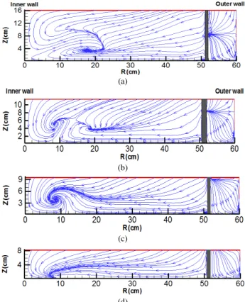
Study on flow pattern in longitudinal profile
In Figure (7-a), it can be observed that in a distance of 5 times the length of spur dike, the flow works as a return flow and forms an anticlockwise vortex. In Figure 7 (b), the flow forms an anticlockwise vortex in a distance of 2.5 times the width of the channel. As it can be seen in Figure (7-c), the flow forms an anticlockwise vortex downstream of the spur dike, in a distance of 1.5 times the width of the channel. According to Figure (7-d), it is observed that in a distance of 5% of the width of the channel from the web, a small clockwise vortex is formed. Also, another flow downstream and behind the web of the spur dike, in a distance of 6 times the length of the spur dike works as a return flow and forms an anticlockwise vortex. Also, with an increase in Froude Number, the distance of the return flow downstream and from the web of the spur dike has increased by 10%.
(a)
(b)
(c)
(d)
Figure 7: stream lines in cross section in a distance of 5% of the width of the channel from the external bend, with an unsubmerged spur dike and various
Fr= a) 0.2 b) 0.34 c) 0.45 d) 0.6
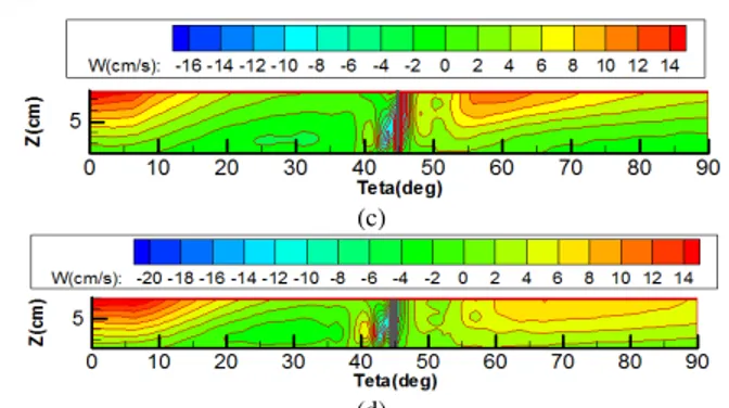
According to Figure (8), maximum vertical velocity of the flow is found upstream and downstream of the spur dike. Also, when Froude Number increases, maximum vertical velocity of the flow will be upstream of the web and increases by about 1.4 times.
(a)
Volume No.3, Issue No.5, pp : 351-355 01 May 2014
IJER@2014
Page 354
(c)
(d)
Figure 8: changes in vertical velocity of the flow in cross section in a distance of 5% of the width of the channel from the external bank, with an unsubmerged spur dike and various Fr= a) 0.2 b) 0.34 c) 0.45 d) 0.6 Study on flow pattern in plan
As it is seen in Figures (9-a) and (9-d), the flow is directed toward the external bend and it continues toward the end of the channel. But in Figures (9-b) and (9-c), continues toward downstream after the formation of the vortex.
(a)
(b)
(c)
(d)
Figure 9: stream lines in plan section near the bed, with an unsubmerged spur dike and various Fr= a) 0.2 b) 0.34 c) 0.45 d) 0.6
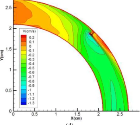
Based on Figure (10), maximum lateral velocity is found upstream the wing of the spur dike. Also, with an increase in Froude Number, lateral velocity also increases by about 1.5 times.
(a)
(b)
Volume No.3, Issue No.5, pp : 351-355 01 May 2014
IJER@2014
Page 355
(d)
Figure 10: changes in lateral velocity of the flow in the level near the bed, with an unsubmerged spur dike and various Fr= a) 0.2 b) 0.34 c) 0.45 d) 0.6
IV. Conclusion
As Froude Number increases: Vertical velocity of the flow increases by about twice.
The distance between return flows and the web of the spur dike increases by about ten times.
Maximum vertical velocity of the flow is found upstream the web of the spur dike. Also, at the end of the channel it is about 5 or 6 times more than that at the beginning.
References
i. Yaeger M.A., (2009). Mean flow and turbulence around two series of experimental dikes. MSc thesis, University of Arizona, Department of Hydrology and Water Resources.
ii. Ahmad M., (1951). Spacing and protection of spurs for bank protection. Civil Engineering and Publicationreview, Vol. 46, Part 1, pp. 3-7.
iii. Ahmad M., (1953). Experiments on Design and Behavior of Spur dikes. Proc. Of Cong. Of IAHR, pp. 145-159.
iv. Rajaratnam N. and Nwachukwu B. A., (1983a). Erosion near groyne structures. Journal hydraulic Res., IAHR, Vol. 21, No. 4, pp. 227-287.
v. Rajaratnam N. and Nwachukwu B. A., (1983b). Flow near
groyne-like structures. Journal of hydraulic engineering, ASCE, Vol. 109, No. 3, pp. 463-480.
vi. Soliman M. M., Attia K. M., Kotb Talaat A. M. and Ahmed A. F., (1997). Spur Dike Effects on the River Nile Morphology after High Aswan Dam. Congress of the International Association of Hydraulic Research, LAHR, Vol. 120, No. 9, pp. 125-146.
vii. Giri S., Shimizu Y., and Surajata B., (2004). Laboratory Measurement and Numerical Simulation of Flow and Turbulence in a Meandering-Like Flume with Spurs. Flow Measurement and Instrumentation, Vol.15, pp. 301-309.
viii. Nagata N., Hosoda T., Nakato T., and Muramoto Y., (2005). Three-dimensional numerical model for flow and bed deformation around river hydraulic structures. Journal of hydraulic engineering, Vol. 131, No. 12, pp. 1074-1087.
ix. Ghodsian M. and Vaghefi M., (2009). Experimental study on scour and flow field in a scour hole around a T-shapespur dike in a 90° bend. Journal of Sediment Research, Vol. 24, No. 2, pp.145-158.
x. Duan J. G., He L., Fu X., and Wang Q., (2009). Mean flow and turbulence around experimental spur dike. Advances in Water Resources, Vol. 32, No.22, pp.1717-1725.
xi. Naji Abhari M. N., Ghodsian M., Vaghefi M., and Panahpur N., (2010). Experimental and numerical simulation of flow in a 90 bend, Flow Measurement and Instrumentation, Vol. 21, No. 3, pp. 292-298.
xii. Vaghefi M., Godsian M. and Salehi Neyshaboori S.A.A., (2009). Experimental Study on the Effect of a T-Shaped Spur Dike Length on Scour in a 90 degree channel bend. The Arabian Journal for Science and Engineering, Vol. 34, No. 2B.
xiii. Vaghefi M., Ghodsian M. and Salehi Neyshabori S.A.A., (2012). Experimental Study on Scour around a T-Shaped Spur Dike in a Channel Bend. Journal of Hydraulic Engineering, Vol. 138, No.5, pp. 471-474.
xiv. Vaghefi M., Ghodsian M. and Adib A., (2012). Experimental Study on the Effect of Froude Number on Temporal Variation of Scour around a T-shaped Spur Dike in a 90 Degree Bend. Applied Mechanics and Materials, Vol. 147, pp. 75-79.