Obstacle Avoidance Through Visual Teleoperation
Muhammad Usman Keerio
Assistant Professor, Department of Electrical Engineering, QUEST, Nawabshah Pakistan E-Mail: [email protected]
ABSTRACT
This paper presents a novel controlling approach for Humanoid Robot to work safely in critical situations like bad light environment using Visual Teleoperation. In this regard modeling environments for Humanoid Teleoperation System is developed. Here virtual reality modeling environment includes development of virtual Humanoid BHR-2, and virtual objects like table etc. The main goal of this work is to enhance our visual teleoperation system for BHR-2 in order to avoid any collision during real time operation. Software Maya is used for modeling and simulations. Maya plug-ins in VC++ provides efficient modeling rule, real time interaction, and time saving rendering approach in a virtual environment. In this paper the validity of proposed scheme is shown by conducting experiments using offline step over trajectory to avoid obstacle in bad light environment.
KEYWORDS
Virtual Reality, Step over Trajectory, Visual Teleoperation
1. INTRODUCTION
In Teleoperation system, a human operator can control and monitor a remote robot and interacts with an environment while relaying information back to the human. Fundamental requirement for Teleoperation is high-fidelity video information. Cameras are usually unable to provide complete vision feedback especially in case of bad lighting environment. Virtual Reality (VR) can be a better approach for controlling the robot in such situation. If a computer- generated picture is substituted for the video picture, the viewer can be made to fell present (virtual presence, virtual environment, or virtual reality).
Work related to modeling within virtual reality [1] that displays the capability of VR to serve as a creative tool. Method includes drawing 3D lines using a tracker, surfaces based on 3D curves, and 3D objects based on 2D sketches. In [2] the hardware components to implement teleoperator presence with head-mounted display were developed and evaluated. Head position was measured within a worksite. This drove a 7-DOF telemanipulator. To implement on whole body it is very difficult.
Use of virtual reality in both the modeling and animation process is described in [3].
In order to plan motions a 3D knowledge of the environment is needed. Humanoid robot needs 3D representation of the world, can step on and over obstacles [4], [5], and go through narrow spaces and craw [6]. Main goal is to enhance the information available for the remote operator.
In teleoperation, it is necessary the perceptions from a physically remote environment conveyed to the human operator in a realistic manner. This differs from virtual reality in which the perception from a simulated environment is conveyed to the user. Thus virtual environments and teleoperation share many of the same to user interface but in teleoperation the need for detailed world modeling is less fundamental [7], [8].
For better performance of the Humanoid teleoperation, it is desired to provide a complete scene of the robot and its worksite to the operator. One approach used the feedback real video images [9]. Some other teleoperation systems for humanoid robots displayed the real images captured by the cameras on the robot [10], [11], etc. These systems are easy to develop but are not suitable in the case of environment (e.g. full of smoke) camera can not shoot the images clearly for the operator to complete the task.
A better visualization of teleoperation information i.e. a continuously available 3D graphics can be displayed for the robot’s location and its environment using Virtual reality. Researchers focused on building virtual models of the robot and rendering their configuration [12], [13]. But these two systems did not render the robot external data relative to its worksite.
Many types of software are available for VE. Maya can widely be used as visual modeling tool. Maya uses MEL scripting language for components such as dialog boxes and tools, propriety file formats and plug-ins to simplify modeling and animation. This technique helps to ensure the data is updated in an efficient and control manner [14]. In virtual reality based Teleoperation system, real data from the environment experienced with a telaoperator and simulated data that experienced via a VE simulation can be fused via digital processing to produce intermediate environment of real and simulated objects. In this work, modeling refers to the data that are used to record the geometrical information for the environment. This information includes the shape of the objects in the environment, physical properties, and their interaction in the environment and the user for visual presentation of the environment. The main goal of building virtual environment is to describe interactions as well as the visualization of the environment.
system data feedback to operator without simulation, it will be difficult to monitor the robot in critical situation.
In this paper, work of [16] has been enhanced to develop a complete graphical simulation environment/ visual environment using software Maya to teleoperate and monitor real Humanoid under such circumstances where robot vision is not enough to avoid obstacle like in bad light environment, thus our system becomes through the visualisation choice a teleoperation system.
This paper is organised as under: The virtual scene modeling technique is described in the section 2. In Section 3 method of building a virtual Humanoid is described while section 4 describes the procedure to develop virtual objects. In section 5 motion capture system is discussed. Section 6 presents Simulation Environment and the experimental results and in section 7 conclusions are presented
2. VIRTUAL SCENE MODELING
In this section, virtual scene modeling method is discussed. Maya software is selected for this work. It has the model function and rendering function. Building the surface and the skeleton of the role, it can render any motion of the virtual scene. It has the interface to add the function of data processing or other. Virtual scene includes virtual BHR-2 and virtual furniture like table, chair, cupboard, stool, and simply any block etc for visual teleoperation system.
2.1 Modeling Transformation
3D Modeling transformations represented by 4x4 Matrices for scale, rotate, translate; shear, etc are used. For example: to rotate around Z-axis the following matrix shown in (1) can be used.
c s 0
s c 0
0 0 1
0 0 0 1
x y P z (1)
Animation of a rigid body can be defined as arrangement of two transforms or a hierarchy of transforms as under:
positionM atrix * rotationM atrix (2) (5)
1 0 0
0 1 0
0 0 1
0 0 0 1
x y p o s itio n M a tr ix
z (3) 2 2 2 0 0 0
0 0 0 1
Tx c Txy sz Txz sy
Txy sz Ty c Tyz sx rotationMatrix
Txz sy Tyz sx Tz c
(4)
Where x, y and z showing the components of the unit vector along the axis and
s
sin
,c
cos
andT
1
c
. See for more details [17].3. VIRTUAL HUMANOID BHR-2
Firstly, a virtual skeleton model (the two skeletons model) like the BHR-2 has been developed which has 32 DOF. And the setup of the DOF is similar as the real robot. In the Maya software the value of each DOF can be changed, so it can display the mutual movement of two adjacent skeletons. Position and attitude data are accepted by a robot skeleton itself.
After building the skeleton system, the surface of the robot is built by the Maya Tools, attached on the skeleton, the whole robot model is built completely (See fig.1). After developing the robot model, the attributes are added to accept the values. The model can render the robot motion and use the motion data of robot.
The data processing plug-ins is developed using Maya to obtain the motion data from a data file which is updating in time by the teleoperation platform feedback module. In the plug-in the motion data are evaluated to attribute the model joints
The state of the robot can be rendered using Real-time joint angle data and Real-time position and attitude data. The body sensor data feedback to the platform while executing the order. Then the data can be used directly in the virtual scene.
In the motion capture system markers/sensors are used to determine the coordinate’s data of the markers on the robot body. Coordinates data of only 3 markers which are attached on the robot body can be used to obtain the position and the attitude data of the robot body.
The virtual scene of the robot helps operator in following manner:
I. The most important function of the virtual scene is to monitor the robot real-time. By rendering the real-time feedback from the robot; the virtual scene expresses the real situation of the robot and parts of its environment instead of the video picture from real camera.
II. The operator can change the view point easily to see the detail of the robot in environment. The exact state of the robot will be known
4. VIRTUAL OBJECTS
Procedure to make a virtual model of furniture like table etc and to track them in teleoperation is discussed here.
The following modeling operations are used to make 3D shape of table:
Sculpting (either the NURBS or Polygon sculpting tool or by moving vertices, faces, CVS, or edit points), lofting, revolving (lathing), and extruding.
Following steps are involved while drawing a virtual table in Maya.
drawing this curve, choose the “CV Curve” or “EP Curve” tool from “Create” and then, sketch the outline of one side of a table leg on the right hand side of the Y axis in the “Side (XY)” view. After finishing the line, press enter (See Fig.2). Step 2: To make objects (as in this case a leg of table) that are symmetrical around one axis the Revolve tool is used. The results can be edited of the “revolve” by changing the attribute in the channels window by clicking the “revolve1” under the input labels. Thus a table leg appears (fig. 3). Using Lofting Tool a surface between two or more curves can be created. To create a few curves that are in different planes, easy way is to create one curve and then duplicate it and move duplicate away from each other (See fig.4). Objects can be easily bent, twisted, tapered and sheared etc. Select Deform > Create Nonlinear > Bend. Now click and drag to bend the object around the axes in the view as dragged in.
Step 3: Create a table top and position it over the table legs by creating a cube and scaling it accordingly, or changing the values under the inputs in the channel window (See Fig.5).
Step 4: Give a sufficient amount of thickness to the table top so that the legs penetrate in to the table top. Select only the top edges of the table top for beveling the top of the table. Finally a table is created as shown in Fig.6. Using this technique, the other models can be developed.
5. MOTION CAPTURE SYSTEM
Motion capture system can be used to track objects. The real time server processes the data from the motion capture hardware to provide client applications with Cartesian coordinates of the markers. Client code interact how the markers and rigid body define the position and orientation of tracked objects. A motion capture system records the position and orientation of a performer using a number of sensors attached to the body. The sensors may be mechanical, magnetic, or optical. The client can then make calls to the tracked object to receive rigid body motion capture system to be captured and translated to a digital character. Tracked objects based around marker data require clients to specify how the view, up and define a vector. By combining two markers client define a vector. These vectors are added as constraint to the view, up or right vectors of the tracked object using cross product or average mode. Client will specify the position of the tracked object by specifying a list of markers and an associate mode. The server requires at least three markers to track a rigid body.
For instance: moving a virtual chair by placing markers on a physical chair.
The marker based scheme supports tracking/ rendering the shape of rigid and non rigid bodies and is much more flexible. A plug-ins system in Maya allowed user to save data for a virtual environment with the same ease saving a document from a word processor.
By motion capture system, we can obtain the robot motion data. The data is expressed as the coordinates of markers which are attached to the body.
Data structures that are used to record the geometrical information for the environment include the shape of the objects in the environment, their moving parts and physical properties, and the behaviors that they can perform (how they interact with other objects in the environment and with the user). Data-server device is used to get this data. A plug-ins system is developed to save the data for a virtual environment.
Using teleoperation platform, the data of the robot joint angle can be sent back to the operator time. The real-time body sensor data and the motion data are transferred to teleoperation platform. By the real-time data fusion module, these feedbacks will be processed to integrate data which the 3D interface can render. By the virtual model they are finally rendered as the animation. With fusing the feedback data, the strategy is that the robot body sensor data be rendered directly. In fact, by more than 3 markers motion data attached to the rigid body, we can calculate the whole robot position and attitude data. After calculating this data it will be rendered. For more details refer [15].
The joystick can be interfaced to allow user to specify the location of key frames and to modify the current time. Here the simple method has been discussed for loading and interacting with 3D models of robot environment in order to operate and monitor easily.
6. SIMULATION ENVIRONMENT
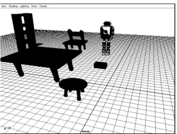
Fig.7 shows the simulation environment for humanoid BHR-2 Teleoperation. Virtual/ Simulation environment shows that through simulation, the overall behavior of the robot system can be visualized and tested under a variety of circumstances.
By this platform, operator watches the virtual scene displayed in a plat screen and can remotely control the humanoid robot to complete the task like walking, etc i.e. stepping over an obstacle by using the control interface. The goal is to visualize robot model for collision free maneuvering to avoid obstacle in case of poor visibility situation
6.1 Evaluation and experimental results
operator input the walking instruction to the robot by keyboard/ joystick. The new motion is calculated and will bring the robot to a stop/ step over. A simulated behaviour of the walking system is shown in Fig.8. When operator detects a potentially dangerous collision, then using step over command causes the robot to follow a step over trajectory. Experimental timing results a step over trajectory can be per formed in roughly 10-20 msec. Simulation scene is shown in fig. 8 whereas the corresponding snapshots of experiment are shown in fig. 9.
From start to step over, figure 9 depicts snapshots for: 1. The beginning of walking motion with stepping starting from the left foot over obstacle.
2. Ending of the walking motion, after stepping over the right foot obstacle.
The results of these experiments proved the effectiveness of the controlling method for visual humanoid teleoperation system.
By the real time stability control, the actual motion trajectory differs from the design trajectory. The virtual scene renders the two kinds of data in the simulation scene and in the real monitoring scene. The difference can be distinguished as the operator observing the details of the robot in the two scenes.
7. CONCLUSIONS
In this paper visual environment for Humanoid BHR-2 Teleoperation System is developed for safe/ collision free manoeuvring. The scene modeling procedure has been described to create the 3D models of objects in the scene. The interface between the virtual BHR-2 and real BHR-2 was developed for rendering the data using teleoperation. Simulation environment shows that through simulation, the overall behavior of the robot system can be visualized and tested under a variety of circumstances. Experiment results proved that the operator sense of presence enhanced for a task in case of poor visibility.
8. REFERENCES
[1] T. Igarashi, S. Matsuoka, and H. Tanaka, “Teddy: A sketching interface for 3D freeform design”, Computer Graphics” Proceedings (SIGGRAPH), pages 409- 416, 1999.
[2] S. Tachi, and H. Arai, “Study on Tele-Existance II: Three-Dimensional Color Display with sensation of Presence” Proceedings of the 1985 International Conference on Advanced Robotics, Tokio, Japan, Sept. 9-10, 1985.
[3] R.Turner and E.Gobbetti. “Interactive construction and animation of layered elastically deformable characters”, Computer Graphics Forum, 17(2):135{152, 1998.
[4] K. Okada, T. Ogura, A. Haneda, and M. Inaba, “Autonomous 3d walking system for a humanoid robot based on visual step recognition and 3d foot step
planner,” in Proc. IEEE Int.Conf. on Robotics and Automations, 2005, pp. 625–630.
[5] Y. Guan, K. Yokoi, and K. Tanie, “Feasibility: Can humanoid robots overcome given obstacles?”in Proc. IEEE Int. Conf. on Robotics and Automations, May 2005, pp. 1066–1071.
[6] F. Kanehiro, T. Yoshimi, S. Kajita, M. Morisawa, K. Fujiwara, K. Harada, K. Kaneko, H. Hirukawa, and F. Tomita, “Whole body locomotion planning of humanoid robots based on a 3d grid mapm,” in Proc. IEEE Int. Conf. on Robotics and Automations, 2005, pp. 1084–1090.
[7] R. Papasin, B. J. Betts, R. Del Mundo, M. Guerrero, R.W. Mah, D. M. McIntosh, E. Wilson, “Intelligent Virtual Station”, Proc. 7Ih In?. Symp. on ArnJ7cial Intelligence, Robotics and Automation in Space, Nara, Japan (2003).
[8] HUANG, A. HUANG, Z., PRABHAKARAN, B., AND C. R. RUIZ, J. 2003, Interactive visual method for motion and model reuse. In GRAPHITE ’03: Proceedings of the 1st international conference on Computer graphics and interactive techniques in Australasia and South East Asia, ACM Press, New York, NY, USA, 29–36.
[9] Fiorini P, Bejiczy A, and Schenker P, “Integrate Interface for Advanced teleoperation”, IEEE Control Systems, vol.13, N5, 10/93, pp15-19.
[10] Hitoshi Hasunuma and Katsumi Nakashima, “The Tele-operation of the humanoid robot, Workspace Extension of the Arm with Step Motion”. Proceeding of 2005, 5th IEEE-RAS International Conference on Humanoid robots, pp 245-252.
[11] Sokho Chang, Jungtae Kim, et al. “KIST Teleoperation System for Humanoid Robot”, Proceedings of the 1999 IEEG/RSJ International Conference on Intelligent Robots and Systems, pp 1198-1203.
[12] Jonathan Kofman, et al. “Teleoperation of a Robot Manipulator Using a Vision-Based Human-Robot Interface, IEEE transactions on industrial electronics, vol.52, October 2005.
[13] James J. Kuffner Jr., Satoshi Kagami, etal. “Graphical Simulation and High-Level Control of Humanoid Robots”, In the proceeding 2000 IEEE RSJ Int’I conf. on Intelegent Robot and Systems (IROS 2000).
[14] Alias.Maya, http://www.alias.com. Computer programing.
[15] Lei ZHANG, Qiang HUANG, yuepin LU, Tao XIAO, Jiapeng YANG, and Muhammadusman KEERIO, “Visual Teleoperation System for the Humaoid BHR-02” Proceedings of IEEE, IROS 2006.
[17] Craig J. J. “Introduction to Robotics: Mechanics and Control”, Addison-Wesley, 1989.
–
Figure 1. Virtual BHR-2
Figure 2. the curve or simply the cross-section of a symmetrical object
Figure 3. the 3D shape of original curve
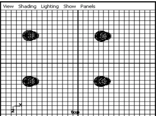
Figure 4. Position of legs of the table after duplicating
Figure 5. position of legs to support table top
Figure7. Simulation environment
Figure 8. Visual Environment for BHR-2 following step over trajectory