Zhang, K., et al.: Induced-Charge Electroosmosis Around Conducting and Janus …
1502 THERMAL SCIENCE, Year 2012, Vol. 16, No. 5, pp. 1502-1505
INDUCED-CHARGE ELECTROOSMOSIS AROUND CONDUCTING
AND JANUS CYLINDER IN MICROCHIP
by
Kai ZHANGa*, Fu-Zhen TIANa, and Ming-Zhou YUb a Department of Mechanics, China Jiliang University, Hangzhou, China
b College of Science, China Jiliang University, Hangzhou, China
Short paper DOI: 10.2298/TSCI1205502Z
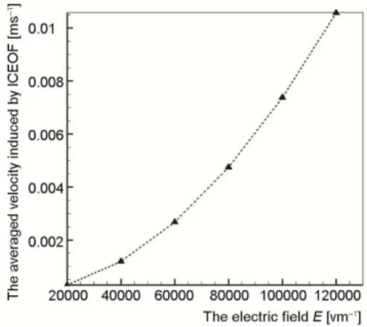
The induced-charge elecetroosmosis around conducting/Janus cylinder with arbitrary Debye thickness is studied numerically, when an direct current weak electric filed is suddenly applied in a confined microchannel. It’s found that there are four large ci r-culations around the conducting cylinder, and the total flux in the microchannel is ze-ro; there are two smaller circulations around the Janus cylinder, and they are com-pressed to wall. A bulk flux, which has a parabolic relation with the applied electric field, is also predicted.
Key words: induced-charge electroosmosis, conducting, microchip
Introduction
The advent of microfluidic technology raises the fundamental question of how to pump and mix fluids at micron scales, where pressure-driven flows and inertial instabilities are suppressed by viscosity [1-3]. Recently, the most popular non-mechanical pumping and mixing strategy is based on electro-osmosis, which is produced by the linear interactions of the externally applied electric field with its immobile electrostatic surface-charge [4]. Howev-er, there are some shortcomings for electroosmosis, but these drawbacks do not apply to in-duced-charge electroosmosis (ICEOF) [5]. In addition, in comparison with EOF, the velocity of ICEOF may be higher because of its non-linear dependence on the applied electric field. Those unique characteristics may lead to new applications in microfluidics and nanofluidics. Recent research includes using ICEOF for mixing and flow regulating [6, 7] and promoting stirring and chaotic advection [8, 9]. Wang et al. [10] indicated that a step change in zeta po-tential will cause a significant variation in the velocity profile and pressure distribution of the flow. Wang et al. [11] found that the barriers periodically embedded in the microchannel are beneficial to the chaotic mixing in that the barriers can form a group of linked twist maps that possess the Bernoulli property and the chaotic advection in these regions. However, those studies employ many assumptions to model ICEOF such as homogeneous dilute electrolytes which is unbounded, rigid spherical particles which is much larger than the thickness of the EDL, very far from any walls or other particles, and uniform and weak field. With the current focus in nanotechnology, one may encounter particles whose linear dimension is comparable with the Debye-layer thickness.
––––––––––––––
Zhang, K., et al.: Induced-Charge Electroosmosis Around Conducting and Janus …
THERMAL SCIENCE, Year 2012, Vol. 16, No. 5, pp. 1502-1505 1503
In general, those studies suggest that a rich variety of nonlinear electrokinetic phenome-na at polarizable surfaces remains to be exploited in microfluidic devices. The impetus of this pa-per is to advance the understanding of ICEOF around a conducting/Janus cylinder for arbitrary
Debye thickness in a confined microfluidic channel, and it’s mostly concerned with flow pattern
and its capability of pumping. Unlike previous treatments, this study is carried out with the full Poisson-Nernst-Planck problem formulation, without making any a priori approximations.
Computational model
To understand the basic principles of ICEOF, let us consider a simple case that 2-D conductive or Janus circular cylinder that is immersed in an aqueous solutions shown in fig. 1(a), for clarity, the cylinders are magnified in figs. 1(b) and 1(c) shows the mesh of the com-putational domain. Here W = 100 μm, L = 500 μm, r = 20 μm. In microfluidics the basic equa-tions describing flow should be selected in advance. The continuum approximation is not va-lid if the Knudsen number is larger than 0.1, then other equations instead of Navier-Stokes equation should be used, for example, the Burnett equations [12, 13]. For steady and
incom-pressible flow, those dimensional governing equations are:
( ) ( )
n D n n
(1)
2
0
( )
D
c D c q
(2)
2
0
( )
D
q D q c
(3)
2
f qzen
(4)
2
. zen
v v v q
(5)
For externally applied field φ, φ = φa at inlet and
outlet, ∂φ/∂n = 0 at lateral wall, φ = 0 at conducting
particle surface or ∂φ/∂n = 0 at insulated surface when t = 0, and ∂φ/∂n = –(∂c/∂n)/q at
con-ducing particle surface or ∂φ/∂n = 0 at insulated surface when t 0; for the non-dimensional concentration of ions, c = 2 at inlet and outlet, c = 2 at the lateral wall, and ∂c/∂n = –q (∂φ/∂n) at conducting particle surface or c = 2 at insulated particle surface; for the density of free ions, q = 0 at inlet and outlet, q = 0 at the lateral wall, and ∂q/∂n = –c(∂φ/∂n) at conducting particle surface or q = 0 at insulated particle surface. The control-volume-based method was used to solve these equations, and second-order upwind discretization method was used.
Results and discussion
Consider an initially uncharged spherical particle which is suspended in symmetric z-z binary electrolyte solution (viscosity = 1.003·10–3 kg/ms, density ρ = 998.2 kg/m3, per-mittivity = 80·8.85·10–12 C/Vm). The conducting surface of cylinder is impermeable to ions. And then the concentrations of the cations and anions are identical, say n∞. Identical diffusivi-Figure 1. (a) the computational domain;
Zhang, K., et al.: Induced-Charge Electroosmosis Around Conducting and Janus …
1504 THERMAL SCIENCE, Year 2012, Vol. 16, No. 5, pp. 1502-1505
ties (D = 1.0·10–9 m2/s) assumed for both ionic species. All the numerical solutions presented in the following have been carefully studied such that grid-independent solutions are obtained. As shown in fig. 2 once the electric field is suddenly applied over the object, a non-zero cur-rent goes from the aqueous solution to the conductive surface. Thus, the electric field lines in-itially intersect the conductive surface at right-angles as shown in figs. 2(a) and 2(c).
Figure 2. Schematic of electric field in the computational domain
Figure 3. Induce charge density and ICEO flow around conducting and Janus cylinder (t τc)
The current drives positive charges into a thin layer on one side of the conductor and the negative charges into the other, inducing an equal and opposite surface charge q on the conductive surface and also attracting equal and opposite image charges within the conductor itself. Over a charging time τc = Dr/D, which is quite short for a highly polarizable conduc-tor, the conductor behaves like an insulator as shown in figs. 2(b) and 2(d).
From figs. 3(a) and 3(c) it can be seen that induced charge density on particle sur-face is no longer a constant and varies with phase angle. Consequently, the slipping velocity on the conducting surfaces is induced by the interaction between electric field and the induced charge density and changes with position, re-sulting in a non-uniform flow field.
Due to the oppositely charged surfaces, flow circulations are generated near the em-bedded cylinder in the channel as shown in
figs. 3(b) and 3(d). Around conducting cy-linder there exists four circulation regions, they can be used to mix sample effectively; as shown in fig. 3(c), around Janus cylinder, there exists two symmetric circulation re-gions, which can be used as to pump and mix sample in microchannel.
As shown in fig. 4, the induced electroos-motic velocity increases with the growth of externally applied electric field, which means that Janus cylinder immersed in microchannel can be used as pump.
Zhang, K., et al.: Induced-Charge Electroosmosis Around Conducting and Janus …
THERMAL SCIENCE, Year 2012, Vol. 16, No. 5, pp. 1502-1505 1505
Conclusions
It is found that there are four large circulations around the conducting cylinder while the total flux in the microchannel is zero; there are two smaller circulations around the Janus cylinder and they are compressed to wall, and there is bulk flux which has a parabolic relation with applied electric field. These conclusions may be helpful to the design of mixer and pump in microfluidics.
Acknowledgment
The work was supported by National Natural Science Foundation of China with Grant No. 10902105/10802083, the Qianjiang talent plan B of Zhejiang Province with Grant No. 2010R10014.
References
[1] Li, Z. H., Lin, J. Z., Nie, D. M., New Approach to Minimize Dispersion Induced by Turn in the Capil-lary Electrophoresis Channel Flows, Applied Mathematics and Mechanics, 26 (2005), 6, pp. 685-690 [2] Wang, R. J., Lin, J. Z., Li, Z. H., Study on the Impacting Factors of Transverse Diffusion in the
Micro-channels of T-sensors, Journal of Nanoscience and Nanotechnology, 5 (2005), 8, pp. 1281–1286 [3] Wang, R. J., Lin, J. Z., Numerical Analysis on a Passive Chaotic Micromixer with Helical Microchanne,
Journal of Nanoscience and Nanotechnology, 6 (2006), 1, pp. 190-194
[4] Stone, H., Stroock, A., Ajdari, A., Engineering Flows in Small Devices: Microfluidics toward a Lab-on-a-chip, Annual Review of Fluid Mechanics, 36 (2004), pp. 381-411
[5] Yariv, E., Miloh, T., Electro-Convection about Conducting Particles, Journal of Fluid Mechanics, 595
(2008), pp. 163-172
[6] Wu, Z., Li, D. Q., Micromixing Using Induced-Charge Electrokinetic Flow, Electrochimica Acta, 53
(2008), 19, pp. 5827-5835
[7] Wu, Z., Li, D. Q., Mixing and Flow Regulating by Induced-Charge Electrokinetic Flow in a Microchan-nel with a Pair of Conducting Triangle Hurdles, Microfluids and Nanofluids, 5 (2008), 1, pp. 65–76 [8] Zhao, H., Bau, H., Microfluidic Chaotic Stirrer Utilizing Induced-charge Electro-osmosis, Physical
Re-view E, 75 (2007), 6, 066217-066225
[9] Zhao, H., Bau, H., On the Effect of Induced Electro-Osmosis on a Cylindrical Particle Next to a Sur-face, Langmuir, 23 (2007), 7, pp. 4053-4063
[10] Wang, R. J., Lin, J. Z., Li, Z. H., Analysis of Electro-Osmotic Flow Characteristics at Joint of Capilla-ries with Step Change in ζ-potential and Dimension, Biomedical Microdevices, 7 (2005), 2, pp. 131-135 [11] Wang, R. J., Lin, J. Z., Li, H. J., Chaotic mixing on a Micromixer with Barriers Embedded, Chaos
Soli-tons & Fractals, 33 (2007), 4, pp. 1362-1366
[12] Bao, F. B., Lin, J. Z., Linear Stability Analysis for Various Forms of One-Dimensional Burnett Equa-tion, Inter. J. of Nonlinear Sciences and Numerical Simulation, 6 (2005), 3, pp. 295-303
[13] Bao, F. B., Lin, J. Z., Shi, X., Burnett Simulations of Flow and Heat Transfer in Micro Couette Flow Using Second-Order Slip Conditions, Heat and Mass Transfer, 43 (2007), 6, pp. 559-566