THE INFLUENCES OF THE DIFFERENT PGA’S AND HEIGTHS OF
STRUCTURES ON STEEL BRACED FRAME SYSTEMS EQUIPPED WITH
ADAS DAMPERS
G.R.Abdollahzadeh1& M. Bayat2*
1
Department of Civil Engineering, Babol University of technology, P.O. Box 484, Babol, Iran
2
Department of Civil Engineering, Shomal University, P.O. Box 731, Amol, Iran * Email: abdollahzadeh@nit .ac.ir , M ahmoud_Bayat @hot mail.com
ABSTRACT
The behavior of braced steel frame structures is of special importance due to its extensive use. Also the applications of active and semi-active control systems have increased significantly due to their benefits in obtaining better seismic performance.The main purpose of this paper is to determine the behavior of structures equipped with yielding dampers (ADAS), located in far fields based on energy concepts. In order to optimize their seismic behavior, the codes and solutions are also presented. Three cases with five, ten and fiftheen –story four-bay Concentric Braced Frames (CBF) with and without ADAS were selected. The nonlinear analysis is performed using the "Perform 3D V.4"software and the conclusions are drawn upon energy criterion.Finally, to increase the energy damping ability and reduce the destructive effects in structures on an earthquake event, so that a great amount of induced energy is damped and destruction of the structure is prevented as much as possible by using ADAS dampers.
Keywords:Yielding Dampers (ADAS); Steel Braced Frame, Energy Dissipation Devices.
1. INTRODUCTION
Development and subsequent implementation of modern protective systems, including those involving passive energy dissipation, the entire structural engineering discipline has changed a lot. Various energy dissipation devices such as modifying rigidities, masses, dampings or shapes are used and also the ductile structure is capable of absorbing forces to control the structural vibrations induced by earthquakes or wind excitations. In general, structural control devices can be divided into three classes: passive control, active control and semi-active control [1]. An active control device is known as a system which typically requires a large power source for operation of actuators which supply control forces to the structure. A semi active control system is similar to the active control systems but the external energy requirements are orders of magnitude smaller than typical active control systems [1-3]. A passive control system is defined as a system which does not requires an external power source for vibration response. Using energy dissipating devices in earthquake engineering has two important aspects in the applications, one of which is having a stable and sufficiently large dissipation capacity capable of controlling the earthquake response of the structure, and the other is having a representative model of its cyclic behavior. Different devices have been developed based on the use of low-yield metals with triangular and hourglass shapes [4–7].These shapes are selected to spread yielding throughout the device, thus increasing the work dissipated internally by the structure. Among the best known devices are the patented added damping and stiffness device (ADAS) and variations such as the TADAS [5, 6] and Honeycomb damper [7].The effectiveness of steel devices in reducing the earthquake response of structures has been shown experimentally in the past [4, 5]. As an example, ADAS devices have been used in the seismic retrofit of several structures in Mexico City [8].Plasticity in low-yield metals satisfies the first condition as long as geometric effects due to large deformations in the device are not significant. On the other hand, several models of increasing accuracy have been proposed to represent the cyclic behavior of steel dampers subject to small deformations [5, 9–16].
IJRRAS ●August 2010 Abdollahzadeh & Bayat●Steel Braced Frames with ADAS Dampers
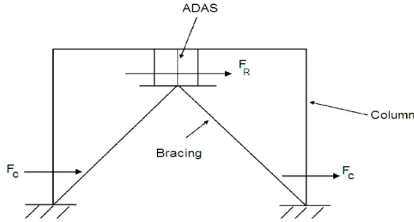
Figure 1.Arrangement of ADAS devices
2. ADAS DESIGNING PROCEDURE 2.1 Characteristics of ADAS devices
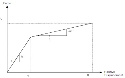
Experimental studies illustrate that the ADAS devices have nonlinear behavior under rush ground motions Tasi et al
[13].In order to simulate the seismic behavior of ADAS devices, a bilinear behavior between shear force and relative displacement is concluded. Thus, the ADAS devices bearable forces are given as
(
),
R y R y
F
k
ak
(1)where
a
is an unknown coefficient to be determined from the experimental data,K
is defined as the elastic stiffness of the ADAS devices and
R and
y represent the maximum relative displacement and yield displacement of the ADAS devices, respectively (see figure 2).The ADAS devices provide reliable energy dissipation as they possess stable hysteresis loops through the yielding of steel plates. To achieve the aforementioned goal, it is imperative to choose a reasonable and acceptable ductility ratio range.The ductility ratio
is defined as;R
y
(2)Let
N
represent the number of steel plates andK
represent the stiffness of a steel plate. We haveK
NK
. Substitution of Eq. (2) into Eq.(1) leads to
F
R
k
y
ak
(
y
y)
k
y(1
a
a
)
KN
y(1
a
a
)
(3)In accordance with the geometric shape of the steel plates, the stiffness of a steel plate,
K
can be determined; for example,
3
3
(
)
6
EBT
K
Triangular
shape steel plate
H
(4)and
3
3
2
(
)
3
EBT
K
X
shape steel plate
H
(5)where
E
represents the elastic modulus of steel, andB
,T
andH
indicate the base width,thickness and height of the steel plates, respectively.
2.2 Seismic forces and the effects of ADAS device design
The bracing members are considered rigid in stiffness when designing a building with damping devices. The reactive forces due to seismic impact on the building mainly include column shear forces and ADAS-absorbed forces (
F
C andF
R in figure 3). The ADAS devices are designed to be able to absorb impact to keep the column shear forces less than the designed column shear forces at any time. Generally, ADAS devices are designed after a Concentric Braced Frames has been designed to meet the seismic building provisions. LetF
T be the maximumstory shear forces of structures without ADAS devices on each story during earthquakes,
F
D be the designedcolumn shear forces and
F
R represent the resistant forces of ADAS dampers that we design. IfF
T >F
D, the goalof using the dampers is to absorb
F
T
F
D so thatF
C will not exceedF
C during the earthquake. The above implies
F
R
F
T
F
D (6)IJRRAS ●August 2010 Abdollahzadeh & Bayat●Steel Braced Frames with ADAS Dampers
Further, in Eq.(3), we use the designed ductility ratio
d instead of the resulting ductility ratio
whenN
plates are used. Then, Eq.(5) leads to the number of steel plates for the ADAS devices to achieve the above goal:
(1
)
T D
y
F
F
N
KN
a
a
(7)
3. STUDY ON THE EFFECTS OF THE ENERGY DISSIPATIMNG SYSTEMS
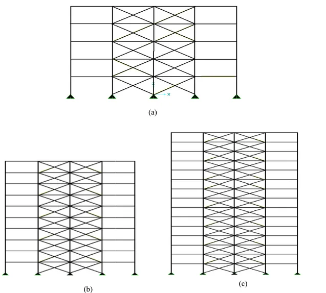
In order to show the effectiveness of the damper in this study attempt has been made to analyze the same structure without any dampers. Three cases with five, ten and fiftheen –story four-bay Concentric Braced Frames, with and with out ADAS (see figure8) devices were selected to illustrate the effeiciency of using this kind of energy dissipative systems. The frames were designed prior to this study in accordance with Uniform Building Code 97 requirements, based upon the static analysis using the criteria tabulated in table 1.
Table 1. Analysis Criteria
Structure Type Seismic Zone Soil Type Seismic Source Distance from Fault Concentric Braced
Frame Four
c
S
A 10 km (7.5 miles)The Poisson’s ratio and elastic modulus for the structure are equal to 0.3 and 2.0 ×10⁸ kPa (2.9 ×10⁴ ksi), respectively.The ADAS devices are fabricated on each floor and are supported by chevron bracing. The value of
a
in Eq. (1) is considered to be 0.12, and the range of the ductility ratios for the ADAS dampers is controlled between 3 and 5.
Table2. The properties of dampers
Width height thickness
12.7 cm 8.0 cm 3.26
(b)
Figure.4. Different studied cases
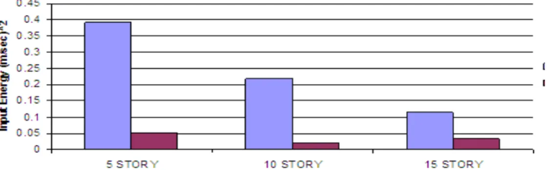
4. RESULTS AND DISCUSSIONS Table 3 and figure 5 illustrate the amount and CBF systems under different PGAs for in the height of the structure on the input the height of the structure increases, the rate in ADAS system is larger than that input Hysteretic energy are illustrated in energy is increased by adding to the PGA. T
Table 3. Calcula
Earthquake
Number
of Bay PGA
Imperial Valley 4 BaY
0.4
0.6
0.8
(a)
(c)
ied cases. (a) 5-story building (b) 10-story building (c) 15-story buildin
USSIONS
the amount of the Hysteretic energy for the case of Imperial Valley PGAs for 5, 10 and 15 - 4bay CBF and ADAS systems. The effects o the input Hysteretic energy are depicted in figure 6. As it is show increases, the values of Hysteretic energy for both systems are decreased
than that in CBF. The influences of the variations of PGA of the illustrated in figures 7 and 8. As shown in these figures, the value dding to the PGA. This increase is larger for the ADAS system than for CB
. Calculated Hysteretic energies for different PGAs
PGA
5 STORY 10 STORY
ADAS CBF ADAS CBF
0.4g 0.17 0.00 0.63 0.00
0.6g 0.33 0.02 0.15 0.00
0.8g 0.51 0.13 0.28 0.05
story building
Imperial Valley for both ADAS The effects of the increase is shown in this figure, as decreased and the decrease PGA of the structures on the the value of the Hysteretic than for CBF.
15 STORY
ADAS CBF
0.01 0.00
0.06 0.01
IJRRAS ●August 2010 Abdollahzadeh & Bayat●Steel Braced Frames with ADAS Dampers
Figure 5. Comparison of Hysteretic energies for different considered buildings
Figure 6. Effects of the number of building stories on Hysteretic energy
Figure 7. The influence of different PGA’s on Hysteretic energy
5. CONCLUSIONS
The current study shows the difference of building behaviors with and without damper during earthquake vibrations. This study implements the commercial package Perform 3D.V4, information regarding the seismic hazard, passive control system and nonlinear structural response. The energy dissipation device significantly increases the resistance of the structure components to the dynamic loads and they are effective in reducing the seismic response of the structures. The benefits of the energy dissipaters have been clearly demonstrated by these comparative data and the improvement in performance of structure during earthquake excitation have been proved. In addition, the considerable effect of the ADAS dampers in absorbing Hysteretic energy is illustrated. The passive control system absorbs the vibrations automatically without the need of an electrically controlled system. Passive control systems are generally low in cost and effective for support of buildings subjected to dynamic vibrations. It will allow practicing engineers to design and use cost-effective seismic dampers in the preliminary design phase effectively, letting them explore the cost factors by comparing different building seismic performance objectives throughout design.
6. REFERENCES