ISSN 1941-7020
© 2008 Science Publications
Corresponding Author: Amir Saedi Daryan, K.N. Toosi University of Technology, P.O. Box 15875-4416, Vali Asr St.,
Seismic Behavior of Vertical Shear Links made of Easy-Going Steel
1
Amir Saedi Daryan,
1Hesam Bahrampoor,
1Masood Ziaei,
1Ali Golafshar and
1Mohammad Amin Assareh
1K.N. Toosi University of Technology, Civil Faculty, P.O. Box 15875-4416, Tehran, Iran
Abstract: Problem Statement: Since the time that steel was first used as a construction material, engineers have attempted to increase strength, reduce weight and produce more economical structures by using elegant member sections. However, the increase in steel strength and the decrease in cross section area are not always useful and in some cases it is necessary to reduce the strength to allow the structure to behave in a specific manner. This issue is seen in systems designed to withstand lateral loads, such as wind and earthquake loads. Approach: To improve the seismic behavior of braced frames, the V-EBF system with shear panels made of easy-going steel is presented. Using the finite element method, braced frames with shear panels made of easy-going steel were analyzed and compared to the behavior of the same frame with shear panels made of construction steel. The influence of shear panel systems made of easy-going steel is investigated by inserting this system in 4, 8 and 12-storey frames and analyzing them under earthquake loads. Results: The results indicate that contrary to shear panels made of construction steel no local buckling occurs in shear panels made of easy-going steel and the energy dissipation and ductility are increased considerably. Consequently, frames with shear panels made of easy-going steel exhibit better performance and energy absorption. Conclusion: In this research, it is attempted to improve the behavior of V-EBF frames by using a new type of steel, EGS, which has a lower yield stress than construction steel. The study shows that if EGS is used in a shear panel, seismic behavior of these frames improves noticeably.
Key words: Easy-going steel, shear panel system, V-EBF frame, finite element modeling, earthquake record, energy
INTRODUCTION
In the past, moment-resisting and concentrically braced frames were common structural systems used for seismically resistant steel structures. However, these lateral load resisting systems can not economically meet seismic requirements, namely stiffness and ductility, concurrently. In the mid 1970s, researchers invented an eccentric lateral load resisting system that could fulfill both seismic design criteria economically. In this system, accommodating openings is possible. These Eccentrically Braced Frames (EBFs) were first used as a common lateral load resisting system in the early 1980s. However, despite high seismic energy dissipation, this system has substantial disadvantages. In addition, in industrial structures such as power plants, deep beams are sometimes used to carry the loads of heavy and highly sensitive equipment. In these cases, to assure the efficiency and accuracy of equipment, load-bearing members like beams and
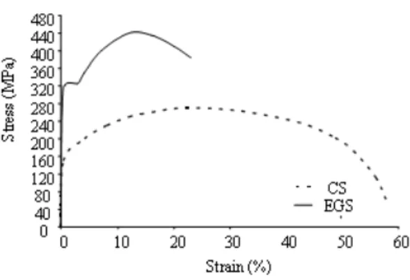
Fig. 1: Stress-strain curve of construction steel and EGS
performance is very important. One of the parameters affecting the behavior of the shear panel is the steel type.
If a shear panel is made of Easy-Going Steel (EGS), which yields at smaller displacements compared to Construction Steel (CS), its performance and energy absorption will improve and premature local web and flange buckling will be prevented. In EGS, the percentages of carbon and other alloys are very low. EGS has high ductility; the most ductile kind of easy-going steel has a nominal yielding stress between 90 N mm−2 -110 N mm−2 and its Young’s modulus is equal to that of construction steel. In Fig. 1, the stress-strain curve of this steel is compared to that of construction steel[6].
MATERIALS AND METHODS
In the following, some general characteristics of easy-going steel in the behavior of braced systems are described. The effect of these characteristics varies with respect to the type of bracing system and whether the entire bracing system, or only some specific members, is made of easy-going steel.
Shear displacement reduction and shear stiffness increase: Displacement of the bracing system consists of shear displacement and bending displacement. In Fig. 2, the combination of displacements in the bracing system is shown.
In these systems, where bending displacements are due to column elongation under axial loads and depend on the column’s cross-sectional area, the system can be regarded as a cantilever beam and bending displacements can be computed. Hence, it can be concluded that bending displacements in bracing
Fig. 2: Combination of displacements in bracing systems
systems having the same span and the same sections are approximately equal. Since EGS is used only in bracing systems and not in columns, the application of EGS in bracing systems does not affect the bending displacements of the systems. These displacements are nearly equal, but because of the fact that the best way to reduce shear displacement is to increase the shear stiffness K of the system (K = F/U, where F is axial force in bracing members, U is shear displacement), using easy-going steel might increase the shear stiffness of the bracing system. Therefore, shear displacements would decrease. The ultimate axial force (Fbu) of the
bracing systems is computed by Eq. 1:
bu 0 b
F = σ .A (1)
Where:
0 = The steel yield stress
Ab = The brace section area.
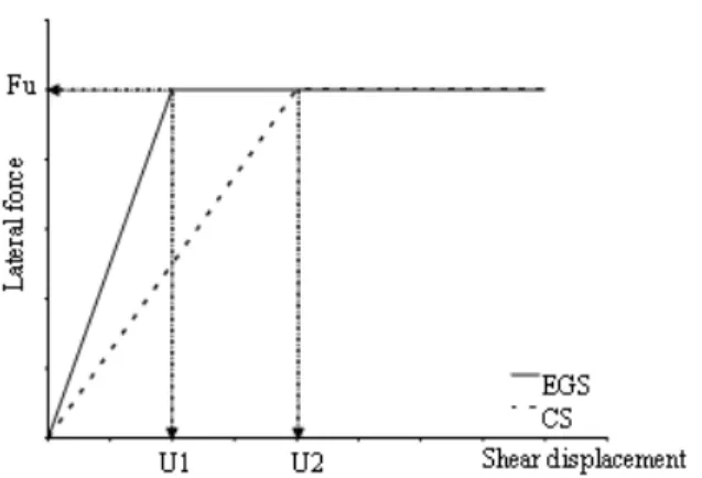
Since each member of the structure is responsible for specific loads, as shown in Fig. 3, the resisting system should have an equal lateral load-bearing capacity (Fu in Fig. 3). Thus, the brace section area (Ab)
in the part of the bracing system where EGS is used should be increased by the ratio of yield limit of construction steel to that of EGS. Since common construction steel has a yield stress of 0 = 250 N mm−
2
and EGS has a yield stress of 0 = 90 N mm−2, this
increase would be around 2.8 (250/90=2.8), which is significant. If high strength steel (high grade carbon) is used rather than common construction steel, this value would be 3.5 (315/90 = 3.5). According to Eq. 1, if the lateral load capacity of the part of the bracing system made of EGS instead of common steel is to be equal to a common steel bracing system, the brace section area of that part of the bracing system (Ab) should be
Fig. 3: Force-shear displacement curve for members made of construction steel and EGS
from the relation K = G*Ab/L, in which G is shear
modulus, Ab is the brace section area and L is the brace
length, respectively, the shear stiffness of that member is increased by increasing the brace section area of the bracing system as much as 2.8 times. In addition, this causes reduction of undesirable effects of the “P- ” phenomenon, especially when the structure enters the nonlinear region to absorb energy.
RESULTS
Local and overall stability improvement using EGS: Using easy-going steel in the whole or part of the bracing systems significantly improves the stability of that part of the system. When EGS is used instead of common construction steel in a part of the bracing system, to achieve equal load-bearing capacity, the section area of the brace should be increased. By increasing the brace section area by 2.8 times, the brace buckling limit stress increases much more than this value.
So, using EGS increases the overall stability in that part of the bracing system considerably and the probability of overall buckling decreases noticeably according to the Euler relation. As is inferred from Euler relation, by using EGS instead of common construction steel in a part of the bracing system, the section areas increase about 2.8 times and it is possible to increase the gyration radius to a desirable limit by choosing suitable sections. The effect of this increase on the improvement of the critical stress corresponding to the buckling limit appears to be of second degree. On the other hand, we can compute the increase of the critical load corresponding to the buckling limit for the increase of Ab and cr. When using EGS instead of
common construction steel, if the section area of a part
of the bracing system is increased by 2.8 times and if the gyration radius of the brace is doubled by this increase, together with choosing a suitable section, the effect on the critical stress corresponding to buckling limit ( cr) is equal to four. In other words, an increase
of the brace section area causes the critical compressive stress to be multiplied by 4. On the other hand, this effect on the critical load corresponding to the buckling limit (Pcr) is equal to 2.8*4 = 11.2, which indicates that
by applying EGS instead of common construction steel in a part of the bracing system, its critical load would increase by 11.2 times. As discussed before, this increment becomes considerable and results in a noticeable improvement of that part of bracing system behavior and the probability of overall buckling in that part decreases. Of course, we should consider that use of EGS has a noticeable effect on local stability and prevention of local buckling because according to the relations in AISC 341-05[7] controls on local buckling prevention are:
Controls in relation with Local flange buckling:
0.5
f f s y
b / (2t )<0.3(E / F ) (2)
Controls in relation with Local web buckling:
0.5
u b y s y
u b y
w 0.5
u b y s y
u b y Forp / p 0.125 3.14(E / F ) * (1 1.54p / p )
h / t
Forp / p 0.125 (E / F ) *MAX(1.49,1.12(2.33 p / p )
ϕ ≤ →
− ϕ
<
ϕ > →
− ϕ
(3)
Where:
tf = The flange thickness of the link beam
h = The height of the link beam tw = The web thickness of the link beam
Es = Young’s modulus of steel fy = The yielding stress of steel
Pu = The weighted design axial force b = A coefficient equal to 0.9
Py = The axial load capacity of the link beam.
By using EGS and the resulting section area increase of the brace, the values of tf and tw increase, so
influence of these parameters varies. If the whole bracing system is made of EGS, the whole shear stiffness is multiplied by approximately 2.8. If the shear panel is made of EGS, there is an increase of lateral stiffness and overall buckling in the shear panel will be lower. In this case, however, characteristics such as local stability improvement, initial stiffness increase and strength increase in the elastic region occur. V-EBF frame design: In this research, the design of V-EBF frames is based on the load-bearing capacity of the shear panel. In every frame, we first suppose specifications for the shear panel section and then other members including columns, beams and braces are designed considering the shear panel capacity. The design of the frames is carried out based on AISC seismic provisions.
Vertical shear panel design: If the shear panel is designed well, it will have high ductility and energy dissipation under earthquake loads. The length of the shear panel should be selected so that the shear panel does not buckle while allowing plastic deformations. This causes the shear panel to reach its maximum load-bearing capacity in the plastic region with a combination of kinematic and isotropic hardening in bending and shear. In limit conditions, shear panels might reach 1.5 *Vpl and 1.5* Mpl in shear and bending due to strain hardening. To cause the panel to fail in shear before bending, the length of the panel is limited by Eq. 4:
( ) p l
p l
0 .3 5 k 1 M e
V +
≤ (4)
In Eq. 4, Mpl is the plastic moment capacity of the
beam and VPL is the shear capacity of the beam section. As a more conservative relation, we have Eq. 5:
pl pl
pl pl
2 1.2M M
e 1.6
1.5V V
×
≤ = (5)
By applying Eq. 5 for the length of the panel and the application of shear stiffeners in the panel web, shear rotation, or in other words the ultimate shear buckling in the panel web can be over 0.1 rad. Eq. 5 is true for a horizontal shear panel whose moments on both sides are equal but as is obvious from the shear and moment distribution of the vertical shear hinge in Fig. 4, its moments at both ends are not equal and the top moment is greater than bottom moment and is proportional to the rotational stiffness of the beam or braces.
Fig. 4: Shear and bending distribution in V-EBF frame
If the shear panel is designed according to this recommendation the energy dissipation capacity will decrease. The other alternative is to reduce the end moment values by decreasing the length of the panel. Hence, the shear panel can bear large plastic deformations and weld failures at the panel connection to the storey beam is avoided. Therefore, it is recommended that the design end moment limit be M=0.5* Mpl. Thus, we have Eq. 6:
( ) pl 2
pl 1
0.7 k 1 M M
e , K
V M
+
≤ = (6)
In this research, we used Eq. 6 for the design of V-EBF frames. The performance accuracy of designed frames according to this method was investigated in reference[8,9]. In this study, we used the finite element method in the program ABAQUS to analyze the seismic behavior of braced frames. We initially used the experimental results[10] to ensure accuracy of the modeling method and the finite element analysis results were then compared to the experimental results.
Vetr test specifications: The resisting core of a three storey, three span building was designed and tested under loads equal to the 0.25g earthquake at the European structure test center located in Italy. In Fig. 5.a, the V-EBF frame elevation and applied sections are shown.
Finite element method: The finite element program ABAQUS was used to model this specimen. All components were modeled by shell elements. The finite element model of the specimen is shown in Fig. 5-b.
(a) (b)
Fig. 5: Frame tested by Vetr a) V-EBF frame elevation and applied sections b) finite element model
0 100 200 300 400 500 600 700 800
0 0.01 0.02 0.03 0.04 0.05 0.06 0.07
Shear Rotation (rad)
S
h
ea
r
L
o
ad
(k
N
)
EXP FE
Fig. 6: Shear force - rotation curve for the first floor of the frame tested
Fig. 7: Deformed shape of V-EBF frame
Comparison of V-EBF frame with EGS shear panels and construction steel: To study the effect of EGS on
Fig. 8: Finite element model of specimen 1-CS
Table 1: Specifications for steel used in modeling
Modulus of Yield stress Ultimate elasticity Material (N mm−2) stress (N mm−2) (N mm−2) Beam and column 358 441 197000 and brace
SPS (With CS) 235 360 197000
SPS(With EGS) 100 250 197000
the improvement of the behavior of V-EBF frames, we conducted an analysis in two separate parts:
Micro study: In the first part of the study, a single storey, single span frame with a V-EBF bracing system is analyzed once with a shear panel made of EGS and then the same frame is analyzed with a shear panel made of common steel (specimen 1-CS). Since the modeling was done using shell elements, it is possible to observe the effect of steel type on behavior of parts of the frame, such as local buckling and stress distributions, in detail. In Fig. 8, the finite element model of specimen 1-CS is presented. Steel specifications used in this investigation are shown in Table 1.
As was mentioned, since any member of a frame should withstand specific loads, it should be supposed that the resisting system has equal ultimate strengths whether using EGS or construction steel. To have equal lateral load-bearing capacities in the shear panel made
of EGS or construction steel (equal Fu); the section area
373 Table 2: The dimensions and sections of frames 1-CS and 1-EGS
1-CS and 1-EGS Section Length(mm)
Beam IPE220 5000
Column IPB240 3000
Brace 2UNP140 3650
SPS(CS) IPE160 300
SPS(EGS) I profile With 300
tf=17.5 mm & tw=11.7 mm
1-CS
1-EGS
Fig. 9: Finite element model of frames 1-CS and 1-EGS
dimensions of the specimen made of construction steel. The dimensions and sections of frames CS and 1-EGS are presented in Table 2. The finite element model of frames 1-CS and 1-EGS after the analysis are presented in Fig. 9. In Figs 10-a and b, the shear force-rotation curve for panels of both specimens and the force-total displacement curve of the frame are presented.
As we observed in Fig. 9 and is expected, if the shear panel is made of EGS, local buckling in the web and the flange of the shear panel does not occur, because of the increased thicknesses of the flange and web. This results in more stability and higher energy absorption by the shear panel. As is obvious from Fig. 10-a, when EGS is used in the shear panel, the shear force that the panel bears with a unit rotation increases considerably relative to when construction steel is applied. Fig. 10-b shows that the initial stiffness of
(a)
(b)
Fig. 10: (a) Shear force - rotation curve of panel (b) force-total displacement curve of the frame
1-EGS is greater than frame 1-CS and the force-displacement curve of 1-EGS is situated at a higher level than the 1-CS system, especially in the elastic region. This behavior represents greater capability of the 1-EGS system to dissipate energy.
Macro study: In this part of the study, to investigate the effect of using shear panels made of EGS on the overall behavior of V-EBF frames, three 4, 8 and 12 storey frames with dimensions shown in Fig. 11 were analyzed once with shear panels made of EGS (EGS series specimens) and again with shear panels made of construction steel (CS series specimens).
Steel specifications used in the frames are the same as those in Table 1. Sections used in frames 4, 8 and 12- EGS and 4, 8 and 12 - CS are presented in Table 3.
Fig. 11: Dimensions of 4, 8 and 12 storey frames
Table 3: Sections in specimens 4, 8, 12 - EGS and 4, 8 and 12 -CS 4-CS & 4-EGS Section
Beam IPE220
Column IPB240
Brace 2UNP140
SPS(CS) IPE160
SPS(EGS) I profile With tf=17.5 mm & tw=11.7 mm
8-CS and 8-EGS Section 4 First story Beam IPE220 Column IPB240
Brace 2UNP140
SPS(CS) IPE160
SPS(EGS) IPE With tf=17.5 & tw=11.7 4 Second story Beam IPE260
Column IPB300
Brace 2UNP180
SPS(CS) IPE200
SPS(EGS) I profile With tf=20 mm & tw=13.2 mm
12-CS and 12-EGS Section 4 First story Beam IPE220
Column IPB240
Brace 2UNP140
SPS(CS) IPE160
SPS(EGS) I profile With tf=17.5 mm & tw=11.7 mm
4 Second story Beam IPE260
Column IPB300
Brace 2UNP180
SPS(CS) IPE200
SPS(EGS) I profile With tf=20 mm & tw=13.2 mm
4 Third story Beam IPE300
Column IPB400
Brace 2UNP240
SPS(CS) IPE220
SPS(EGS) I profile With tf=21.6 mm & 13.9 mm
Pushover analysis: Pushover analysis with a target displacement equal to 3% of the height of every frame was conducted for all specimens. The results are presented in the force- displacement curve in Fig. 12.
As shown in Fig. 12, frame stiffness of the EGS specimens increased noticeably and energy dissipation
Fig. 12: Comparison of force-displacement curves for EGS and CS series specimens
375 Fig. 13: Distribution and energy dissipation applied to
systems and shear panels contribution
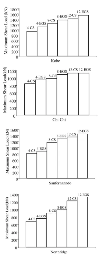
Dynamic analysis: In this section, six modeled specimens of the frame were analyzed under the effect of the Chi-Chi, Northridge, Kobe and San Fernando earthquake records. The maximum displacement of each storey from these earthquakes is shown in Fig. 14. In Fig. 15, the maximum shear force in every frame under the effect of the four records applied to the frame is shown.
As we observe in Fig. 14 and 15, application of EGS did not have much influence on reducing displacements in the 8 and 12 storey frames subjected to the applied records. This is probably due to the fact that use of EGS can only reduce shear displacements and does not affect bending displacements and the structure is most affected by bending displacements with increasing structure height, Consequently, as observed, displacements of the EGS series specimens in the 4-storey frame were slightly lower, but by increasing frame height and domination of bending displacements on the total displacement of structure, the effect of the EGS decreases
Kobe
0 1 2 3 4
0 0.005 0.01 0.015 0.02 0.025 0.0
Drift
St
o
ry
4-CS 4-EGS
Chichi
0 1 2 3 4
0 0.005 0.01 0.015 0.02 0.025 0.03
Drift
S
to
ry
4-CS 4-EGS
Northridge
0 1 2 3 4
0 0.002 0.004 0.006 0.008 0.01 0.012 Drift
S
to
ry
4-CS 4-EGS
Sanfernanndo
0 1 2 3 4
0 0.005 0.01 0.015 0.02 0.025 Drift
S
tor
y
Kobe 0 1 2 3 4 5 6 7 8
0 0.005 0.01 0.015 0.02
Drift S to ry 8-CS 8-EGS Chichi 0 1 2 3 4 5 6 7 8
0 0.005 0.01 0.015 0.02 0.025
Drift S to ry 8-CS 8-EGS Sanfernanndo 0 1 2 3 4 5 6 7 8
0 0.005 0.01 0.015 0.02 0.025 Drift S to ry 8-CS 8-EGS Northridge 0 1 2 3 4 5 6 7 8
0 0.005 0.01 0.015 0.02
Drift S to ry 8-CS 8-EGS
Fig. 14: Comparison of maximum displacement of each storey with easy-going and construction steel under the effect of applied earthquake records
4-CS
4-EGS 8-CS
8-EGS 12-CS 12-EGS 0 200 400 600 800 1000 1200 1400 1600 1800 Kobe M ax im u m S h ea r L o ad ( k N ) 4-CS
4-EGS 8-CS
8-EGS 12-CS 12-EGS
0 200 400 600 800 1000 1200 Chi Chi M ax im u m S h ea r L o ad (k N )
4-CS 4-EGS 8-CS
8-EGS 12-CS 12-EGS 0 200 400 600 800 1000 1200 1400 1600 Sanfernanndo M ax im u m S h ea r L o ad ( k N )
4-CS 4-EGS
8-CS 8-EGS 12-CS 12-EGS 0 200 400 600 800 1000 1200 1400 Northridge M ax im u m S h ea r L o ad (k N )
Fig. 15: Maximum shear force in every frame under the effect of the applied records
377 capability to dissipate energy and also the more stable behavior of internal members of the bracing system, particularly the shear panels, as the main factor in dissipating energy in this system.
DISCUSSION
Using this system in low-rise structures reduces displacements of the system under the effect of seismic loads. In mid-rise and high-rise structures, although displacements of the system under the effect of seismic loads do would not reduce significantly, the capacity of the bracing system to absorb and dissipate energy increases by increasing the capability of the system to withstand lateral forces. This research is a new and
innovative idea and wide and multi-aspect
investigations are necessary to test and use the idea.
CONCLUSION
With the increasing application of EBF frames, particularly in seismic zones, the necessity of studies on EBF types and the application of modern materials to improve behavior of such frames have become widely acknowledged. In this research, it is attempted to improve the behavior of V-EBF frames by using a new type of steel, EGS, which has a lower yield stress than construction steel. The study shows that if EGS is used in a shear panel, seismic behavior of these frames improves noticeably. Using EGS decreases the probability of web and panel buckling to a large extent because of the thickness increase of the sections used in the shear panel. The local stability will improve as well. This fact has a noticeable effect on the improvement in overall frame behavior. Moreover, using shear panels made of EGS increases the total energy dissipated by the braced frame.
ACKNOWLEDGMENTS
The authors would like to thank the Y.M.A Engineering Company for their great support which is much appreciated.
REFERENCES
1. Aristizabal-Ochoa, J.D., 1986. Disposable knee bracing: Improvement in seismic design of steel
frames. J. Struct. Eng., 112: 1544-1552.
http://cedb.asce.org/cgi/WWWdisplay.cgi?8601599.
2. Balendra, T., M.T. Sam and C.Y. Liaw, 1990. Diagonal brace with ductile knee anchor for aseismic steel frame. Earthquake Engg. Struct.
Dyn., 19: 847-858.
linkinghub.elsevier.com/retrieve/pii/014102969500 016Z
3. Balendra, T., M.T. Sam and C.Y. Liaw, 1991. Design of earthquake-resistant steel frames with knee bracing. J. Construct. Steel Res., 18: 193-208. www.eng.nus.edu.sg/research/Research_Achievem ents/Journal_Publications/CE(1991).htm
4. Sam, M.T., T. Balendra and C.Y. Liaw, 1995. Earthquake-resistant steel frames with energy dissipating knee elements. Engg. Struct., 17: 334-343. DOI: 10.1016/0141-0296(95)00016-Z. 5. Zahrai, S.M. and M. Bruneau, 1999. Cyclic testing
of ductile end- diaphragms for slab-on-girder steel bridges. J. Struct. Engg, ASCE, 125: 987 -996. DOI: 10.1061/(ASCE)0733-9445(1999).
6. Sabouri, S., 2004. Lateral Load Resisting Systems and Innovative Idea to Application of Easy-Going Steel (EGS). Anguizeh Publishing Co., pp: 76-85. 7. AISC., 2005. Seismic provisions for structural steel
buildings. Chicago.
http://aec.ihs.com/news/2006/aisc-seismic-provisions.htm.
8. Recommended lateral force requirements and tentative commentary seismology committee, structural engineer’s associate of California, 1996. http://www.seaint.org/rlfhmpg1.htm.
9. Bouwkamp, J.G. and M.G. Vetr, 1994. Design of eccentrically braced test frame with vertical shear links. Proceedings of the 2nd International Conference on Earthquake Resistant Construction
and Design, Berlin.
http://www3.interscience.wiley.com/journal/11402 8768/abstract.
10. Vetr, M.G., 1998. Seismic behavior, analysis and design of eccentrically braced Frames with vertical shear links. Ph.. D. Thesis. University Tech.
Darmstadt W. Germany.