On the effect of the near field records on the steel braced frames
equipped with energy dissipating devices
Abstract
The behavior of braced steel frame structures is of special im-portance due to its extensive use. Also the application of ac-tive and semi-acac-tive control systems, regarding to their ben-efits in obtaining better seismic performance has increased significantly. The majority of the works on steel structures and steel connections has been done under far field records, and the behavior of steel frame structures equipped with yielding dampers under these circumstances has not yet been fully analyzed. The main purpose of this paper is to de-termine the behavior of structures equipped with yielding dampers, located in near field based on energy concepts. In order to optimize their seismic behavior, the codes and solu-tions are also presented.The selected system is a braced steel frame system which is equipped with yielding dampers and the analysis is performed using the “Perform 3D V.4” soft-ware and the conclusions are drawn upon energy criterion. The effect of PGA variation and height of the frames are also considered in the study .Finally, using the above mentioned results, a proper solution is presented for typical systems in order to increase the energy damping ability and reduce the destructive effects in structures on an earthquake event, so that a great amount of induced energy is damped and de-struction of the structure is prevented as much as possible. Keywords
yielding dampers (ADAS), steel braced frame, energy dissi-pation devices, near-fault records.
Mahmoud Bayata,∗ and Gholamreza Abdollahzadehb
a
Department of Civil Engineering, Shomal University, Amol, Iranb
Department of Civil Engineering, Babol University of Technology, Babol, Iran
Received 23 Mar 2011; In revised form 17 Oct 2011
∗Author email: mbayat14@yahoo.com
1 INTRODUCTION
Analyzing nonlinear dynamic model of structures is an interesting area in nonlinear science. During the past few decades, many authors consider the dynamic modeling with damping and without damping and try to analysis them analytically and numerically [1–8, 14, 20, 23, 25].
all [24] considered the Hysteretic dampers for earthquake-resistant structures. Kelly et al [16] had a concentrate review on current uses of energy absorbing devices. To dissipate the energy present in the vibration of a structure during an earthquake, the inelastic deformation of metals can be effective. Many researchers have been worked based on the use of low-yield metals with triangular and hourglass shapes. Among the best known devices are the patented added damping and stiffness device (ADAS) and variations such as the TADAS. These devices exhibit stable hysteretic behavior; they are insensitive to thermal effects, and extremely reliable. A typicalX-shaped plate damper or ADAS (added damping and stiffness) device is shown in Fig. 1. Bergaman et al [9] evaluated the cyclic testing of steel-plate devices for added damping and stiffness. Whittaker et al [35] worked on the Seismic testing of steel plate energy dissipation devices. Tsai et al [32] studied on the Design of steel triangular plate energy absorbers for seismic-resistant construction. Kobori et al [18] developed the work on the application of hysteresis steel dampers. ADAS devices have been used in the seismic retrofit of several structures in Mexico City [28]. Two important aspects in the use of energy dissipating devices in earthquake engineering applications are: (i) to have a stable and sufficiently large dissipation capacity capable of controlling the earthquake response of the structure, and (ii) to have a representative model of its cyclic behavior. Plasticity in low-yield metals satisfies the first condition as long as geometric effects due to large deformations in the device are not significant. On the other hand, several models of increasing accuracy have been proposed to represent the cyclic behavior of steel dampers subject to small deformations [12, 27, 31, 35]. The role of a passive energy dissipator is to increase the hysteretic damping in the structure. This study mainly focuses on the effects of application of ADAS devices – discussing the basic concepts of energy under the near field records. To show the effects and performance of ADAS devices when severe earthquakes occur, three cases consist of five, ten and fifteen–story 3-bay Concentric Braced Frames equipped with and without ADAS devices have been considered. The assumed detail and arrangement of typical ADAS devices are shown in Figure 1.
Many near-fault ground motions have resulted in serious fatalities and severe damage to buildings and bridges in the vicinity of seismic sources during some infamous earthquakes, such as the 1994 Northridge (USA), 1995 Kobe (Japan), 1999 Chi-Chi (Taiwan) earthquakes [11, 15, 19]. Near-fault earthquakes usually have the following features:
1. A high level of peak ground acceleration,
2. A large vertical ground motion,
3. An intense long-period velocity pulse wave.
For the third feature, the velocity pulse that usually occurs at the beginning of a near-fault earthquake is also referred to as the forward rupture directivity effect [10, 29].
Baker [32] proposed an equation and according to that, the pulse period usually can range from 1.4 s to 7 s for a range of earthquake magnitudes from 6 to 7.6 M.
systems) [26, 30]. Bayat considered the work on the steel braced frame structures equipped with ADAS devices under the far field record and in this study, which is an extension of the authors’ previous works [1], the effect of the near field records is considered on the steel braced frames equipped with energy dissipating devices. The near-fault earthquake characteristics outlined above should be considered in the design of structures located in near-fault regions.
Figure 1 Arrangement of ADAS devices [1, 21].
2 OVER REVIEW OF INPUT ENERGY TO A STRUCTURE
Mathematical formulation of a viscous damped SDOF system subject to horizontal earthquake ground motion is [1];
mu¨t+cu˙+fs=0 (1)
If we choose ¨ut=u¨+u¨g = absolute (total) displacement of mass, the equation (1) can be written as ;
mu¨+cu˙+fs= −mu¨g (2)
In which ;
u = relative displacement of the mass with respect to the ground, ug = earthquake ground displacement.
∫ mu du¨ +∫ cu du˙ +∫ fsdu= − ∫ mu¨gdu (3) We achieve these kinds of energies [1];
EI=Ek+ED+EA (4)
EI = Input energy Ek = Kinetic energy;
ED = Damping energy
EA=∫ fsdu =Es+EH = Composed of recoverable elastic strain energy and irrecoverable hysteretic energy.
The Equation (4) is the “Relative” Energy Equation [1, 33].
In this study we considered the “relative” energy method for evaluation of input energy of structures and the total input energy of structures are compared at the time when the earthquake is over and the motion of structure is damped.
For a fixedEI, it is better to increase theEH then the elastic strain energy in the structure becomes minimized.
3 DESIGNING OF ADAS DEVICES
The ADAS devices bearable forces are given as [1, 21];
FR=K′δy+aK′(δR−δy), (5)
a = an unknown coefficient to be determined from the experimental data K′= elastic stiffness of the ADAS devices
δR = maximum relative displacement
δy = yield displacement of the ADAS devices
4 CHARACTERISTICS OF THE NEAR FIELD EARTHQUAKE RECORDS
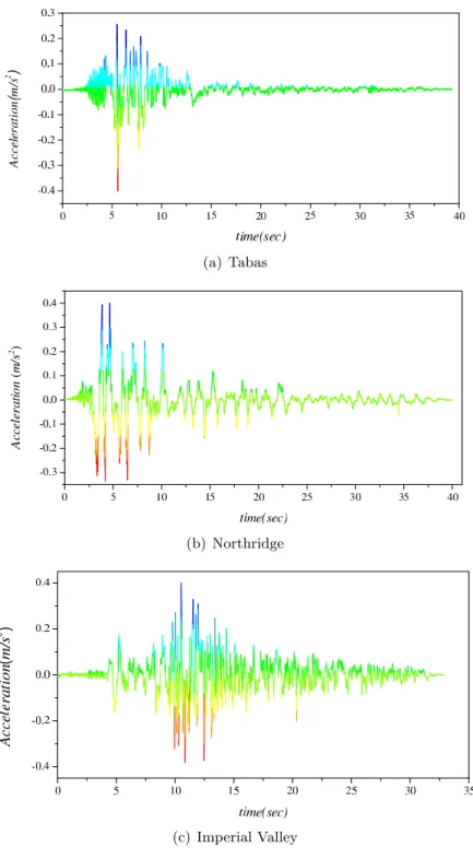
Table 1 is the details of the unscaled earthquake records. In this study, scaled records are used for nonlinear dynamic analysis with PGA scaled to 0.4g, 0.6g and 0.8g. Figure 2a-c represent the acceleration recorded during three earthquake near field records (Tabas, Northridge and Imperial Valley) with PGA = 0.4g.
5 NONLINEAR DYNAMIC TIME HISTORY ASSUMPTIONS
(a) Tabas
(b) Northridge
(c) Imperial Valley
Table 1 Unsealed earthquake records used for non-linear analysis. Near field
Earthquake Imperial Valley Northridge Tabas,Iran
1979/10/15 1994/01/17 1978/09/16
Magnitude M(6.5)Ml(6.6) M(6.7)Ml(6.6) M(7.4)Ml(7.7)
Ms(6.9) Ms(6.7) Ms(7.4)
Station 952 El Centro 74 Sylmar-Converter Sta 9101 Tabas
Data source USGS DWP ——–
PGA 0.519 0.612 0.836
Distance(Km) Closest to fault rapture Closest to fault rapture Hypocentral
(1.0) (6.2) (3.0)
Site Condition CWB(D) CWB(C) CWB(C)
USGS(C) USGS(C)
computation of dynamic response at each time increment concerning due consideration given to the inelasticity in members. Hysteretic energy under cyclic loading is evaluated and tabu-lated. During strong and mediocre earthquakes, structures enter the plastic range. Therefore, it is essential to perform a nonlinear analysis. For this purpose, numerical simulations were carried out by PERFORM 3D.V4 [34].
The frames were designed prior to this study in accordance with Uniform Building Code 97 requirements, based upon the static analysis.
We consider following criterias for this study;
1. Soil type is assumed Sc (very dense soil and soft rock) according to UBC97 [22] code.
2. Earthquake source and structures distance from active fault is 10 km according to type A of UBC97.
3. It is assumed that structures are located in zone 4, according to UBC97.
4. The P-Delta effect is included in the analysis.
5. The non-linear behavior of models is assumed from FEMA273 [13]
6. The plastic hinges in analysis are assumed perfectly elastic-plastic.
7. A 0.005s time step be used for all non-linear analysis of models.
8. Strength loss is ignored in non-linear analysis of systems.
10. Poisson’s ratio = 0.3
11. Elastic modulus = 2.0×10⁶
kPa
12. Yield stress = 2400 cmKg2
13. The properties of dampers are shown in Table 2.
14. Most of the inelastic components in PERFORM-3D have the same form for the F-D relationship. Figure 3 shows a trilinear relationship with optional strength loss.
Table 2 The properties of dampers.
Type of the damper
The Geometric properties
h b-top & bottom B middle t ∆y P y K
(cm) (cm) (cm) (cm) (cm) (Kg) (Kg/cm)
AADAS 12.7 6.35 1.27 0.64 0.2794 306 1094
Figure 3 PERFORM Action-Deformation Relationship [22]. The key points in the relationship are as follows;
1. Y Point. This is the first yield point, where significant nonlinear behavior begins [34].
2. U Point. This is the ultimate strength point, where the maximum strength is reached
[34].
3. L Point. This is the ductile limit point, where significant strength loss begins [34].
4. R Point. This is the residual strength point, where the minimum residual strength is
5. X Point. This is usually at a deformation that is so large that there is no point in
continuing the analysis. You can continue an analysis beyond this point if you wish, but usually you will stop the analysis if any component is deformed beyond its X point [34].
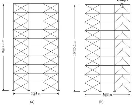
Figure 4 shows a type single CBF and ADAS farmes which are considered in this study.
(a) (b)
Figure 4 Type of studied single frame (a) , b) ADAS.
6 RESULTS AND DISCUSSIONS
6.1 Input energy
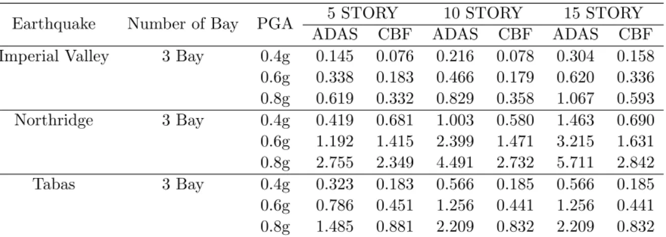
It is obvious that the input energy to a structure is a function of time. In this paper we evaluated the total input energy in the structure to compare their behavior. Table 3 represents the maximum total input energy in different systems.
6.2 Hysteretic energy
The maximum total hysteretic energy at the end of the earthquake is used for comparing in different structural systems. Table 4 shows the maximum total hysteretic energy in different systems.
Table 3 The maximum total input energy per mass (m/sec)2in different systems under different earthquakes.
Earthquake Number of Bay PGA 5 STORY 10 STORY 15 STORY
ADAS CBF ADAS CBF ADAS CBF
Imperial Valley 3 Bay 0.4g 0.145 0.076 0.216 0.078 0.304 0.158 0.6g 0.338 0.183 0.466 0.179 0.620 0.336 0.8g 0.619 0.332 0.829 0.358 1.067 0.593 Northridge 3 Bay 0.4g 0.419 0.681 1.003 0.580 1.463 0.690 0.6g 1.192 1.415 2.399 1.471 3.215 1.631 0.8g 2.755 2.349 4.491 2.732 5.711 2.842 Tabas 3 Bay 0.4g 0.323 0.183 0.566 0.185 0.566 0.185 0.6g 0.786 0.451 1.256 0.441 1.256 0.441 0.8g 1.485 0.881 2.209 0.832 2.209 0.832
Table 4 The maximum total hysteretic energy per mass (m/sec)2 in different systems under different
earth-quakes.
Earthquake Number of Bay PGA 5 STORY 10 STORY 15 STORY
ADAS CBF ADAS CBF ADAS CBF
Imperial Valley 3 Bay 0.4g 0.077 0.008 0.068 0.000 0.095 0.019 0.6g 0.168 0.050 0.139 0.028 0.217 0.135 0.8g 0.272 0.124 0.225 0.121 0.369 0.332 Northridge 3 Bay 0.4g 0.129 0.009 0.133 0.011 0.151 0.048 0.6g 0.290 0.087 0.266 0.075 0.358 0.190 0.8g 0.486 0.270 0.420 0.219 0.633 0.414 Tabas 3 Bay 0.4g 0.168 0.009 0.185 0.021 0.191 0.072 0.6g 0.383 0.115 0.367 0.114 0.462 0.226 0.8g 0.652 0.388 0.572 0.294 0.834 0.455
ratio of the hysteretic energy to the input energy and the effect of different parameters like the height of structures, increasing and decreasing of the PGA’s.
6.3 Effect of increase or decrease in structure height on the ratio of hysteretic energy to input
Figures 5a-c show the comparison of the (Eh/Ei) ratio under for the different near field earth-quake records. Figure 6 represents the average diagram with respect to near field earthearth-quake records and the type of systems. Fig. 6 Shows the effect of changes in the structure height on the input energy in the ADAS and CBF systems, under the near field records.
(a) Imperial Valley
(b) Northridge
(c) Tabas
Table 5 The ratio of the hysteretic energy to the input energy in different systems under different earthquakes.
Earthquake Number of Bay PGA 5 STORY 10 STORY 15 STORY
ADAS CBF ADAS CBF ADAS CBF
Imperial Valley 3 Bay 0.4g 0.466 0.030 0.28 0.00 0.314 0.053 0.6g 0.434 0.080 0.27 0.06 0.350 0.181 0.8g 0.384 0.110 0.24 0.14 0.346 0.252 Northridge 3 Bay 0.471 0.155 0.260 0.131 0.375 0.220 0.471 0.384 0.192 0.214 0.215 0.372 0.274 0.384 0.250 0.205 0.164 0.258 0.371 0.297 0.250 Tabas 3 Bay 0.455 0.014 0.295 0.044 0.312 0.087 0.455 0.427 0.075 0.263 0.104 0.348 0.142 0.427 0.384 0.129 0.233 0.141 0.363 0.180 0.384
Figure 6 The effect of height of structure on (Eh/Ei) under near field records.
6.4 Effect of PGA variation on the ratio of the hysteretic energy to input energy
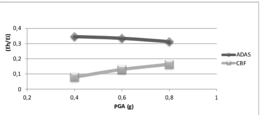
Figs. 7a-c show the effect of the maximum acceleration of the near field records with PGA 0.4g, 0.6g, 0.8g for 5, 10, 15 story buildings. As it is shown in the figures the value of the ratio (Eh/Ei) in the steel braced frame equipped with ADAS devices is more than the CBF systems. This value of the ratio increases with the PGA. The hysteretic-to-input ratio is almost constant for the ADAS system with increasing PGA which means nothing but limitation for an ADAS system in absorption of the hysteretic energy in high values of PGA; nonetheless, the value of hysteretic-to-input ratio is much higher in the ADAS system than that in a CBF one.
(a) Imperial Valley
(b) Northridge
(c) Tabas
Figure 8 The relation between the ratio of the hysteretic energy to input energy with PGA under near field record.
7 CONCLUSION
In this study the effect of the near field records have considered on the steel braced frames with energy dissipating devices (ADAS) and without ADAS devices. Many near-fault ground motions have resulted in serious fatalities and severe damage to buildings and bridges in the vicinity of seismic sources during some infamous earthquakes. We have observed from the behavior of the structures located in the near filed region based upon the frequency content of the earthquake, depends on the geometric specifications of the building including its height. This study shows the difference of building behaviors with and without damper during earth-quake vibrations under the near field records. The influences of the near field records have not too much impact on the 5 story and 10 story building in ADAS systems. In other words the performance of these structures in the near filed region is better than the other structural systems which were considered in this study. The ADAS devices significantly increase the resistance of the structure components to the dynamic loads and they are effective in reducing the seismic response of the structures. The benefits of the energy dissipaters have been clearly demonstrated by these comparative data and the improvement in performance of structures during earthquake excitation have been proved.
References
[1] M. Bayat and G. R. Abdollahzadeh. Analysis of the steel braced frames equipped with adas devices under the far field records.Latin American Journal of Solids and Structures, 8(2):163–181, 2011.
[2] M. Bayat, A. Barari, and M. Shahidi. Dynamic response of axially loaded euler-bernoulli beams. Mechanika, 17(2):172–177, 2011.
[3] M. Bayat, M. Bayat, and M. Bayat. An analytical approach on a mass grounded by linear and nonlinear springs in series. Int. J. Phy. Sci., 6(2):229–236, 2011.
[4] M. Bayat and I. Pakar. Application of He’s energy balance method for nonlinear vibration of thin circular sector cylinder.Int. J. Phy. Sci., 6(23):5564–5570, 2011.
[5] M. Bayat, I. Pakar, and M. Bayat. Analytical study on the vibration frequencies of tapered beams. Latin American Journal of Solids and Structures, 8(2):149–162, 2011.
[7] M. Bayat, M. Shahidi, A. Barari, and G. Domairry. Analytical evaluation of the nonlinear vibration of coupled oscillator systems.Zeitschrift fur Naturforschung Section A-A Journal of Physical Sciences, 66(1-2):67–74, 2011.
[8] M. Bayat, M. Shahidi, and M. Bayat. Application of iteration perturbation method for nonlinear oscillators with discontinuities.Int. J. Phy. Sci., 6(15):3608–3612, 2011.
[9] D.M. Bergaman and S.C. Goel. Evaluation of cyclic testing of steel-plate devices for added damping and stiffness. Technical Report UMCE 87-10, University of Michigan, Ann Arbor, Michigan, 1987.
[10] D.J. Bray and A. Rodriguez-Marek. Characterization of forward-directivity ground motions in the near-fault region.
Soil Dyn Earthq Eng, 11:815–28, 2004.
[11] J.F. Chai and C.H. Loh. Near-fault ground motion and its effect on civil structures. InInternational workshop on mitigation of seismic effects on transportation structures, pages 70–81, 2000.
[12] G.F. Dargush and T.T. Soong. Behavior of metallic plate dampers in seismic passive energy dissipation systems.
Earthquake Spectra, 11(4):545–568, 1995.
[13] FEMA 273, NEHRP guidelines and commentary for the seismic rehabilitation of buildings. Technical Report FEMA 273 (Guidelines), Federal Emergency Management Agency, Washington, D.C., 1997.
[14] E. Ghasemi, M. Bayat, and M. Bayat. Visco-elastic MHD flow of walters liquid b fluid and heat transfer over a non-isothermal stretching sheet.Int. J. Phy. Sci., 6(21):5022–5039, 2011.
[15] J.F. Hall, T.H. Heaton, M.W. Halling, and D.J. Wald. Near-source ground motion and its effects on flexible buildings.
Earthq Spectra, 11:569–605, 1995.
[16] J.M. Kelly and R.I. Skinner. A review of current uses of energy absorbing devices. Technical Report UCB=EERC-79=10, University of California, Berkeley, 1979.
[17] J.M. Kelly, R.I. Skinner, and A.J. Heine. Mechanisms of energy absorption in special devices for use in earthquake resistant structures. Bulletin of the New Zealand Society for Earthquake Engineering, 5:63–88, 1972.
[18] T. Kobori, Y. Miura, E. Fukusawa, T. Yamada, T. Arita, Y. Takenaka, N. Miyagawa, N. Tanaka, and T. Fukumoto. Development and application of hysteresis steel dampers. InProceedings of the 10th World Conference on Earthquake Engineering, pages 2341–2346, 1992.
[19] C.H. Loh, T.C. Wu, and N.E. Huang. Application of the empirical mode decomposition-hilbert spectrum method to identify near-fault ground-motion characteristics. Bull Seismol Soc Amer, 91:1339–57, 2001.
[20] I. Pakar and M. Bayat. Analytical solution for strongly nonlinear oscillation systems using energy balance method.
Int. J. Phy. Sci., 6(22):51665170, 2011.
[21] W. Pong, Z. Lee, C.S. Tsai, and B.J. Chen. Heuristic design procedure for structures with displacement dependent damping devices. Engineering Computations, 26(4):347–359, 2009.
[22] RAM International, L.L.C., University of California.PERFORM 3D.V4, analysis software.
[23] M. Shahidi, M. Bayat, I. Pakar, and G. R. Abdollahzadeh. On the solution of free non-linear vibration of beams.
Int. J. Phy. Sci., 6(7):1628–1634, 2011.
[24] R.I. Skinner, J.M. Kelly, and A.J. Heine. Hysteretic dampers for earthquake-resistant structures. Earthquake Engi-neering and Structural Dynamics, 3:287–296, 1975.
[25] K.S. Soleimani, E. Ghasemi, and M. Bayat. Mesh-free modeling of two-dimensional heat conduction between eccentric circular cylinders.Int. J. Phy. Sci., 6(16):4044–4052, 2011.
[26] B.F. Spencer, J.C. Ramallo, and E.A. Johnson. Smart base isolation systems. J Eng Mech, 128(10):1088–100, 2002.
[27] A. Tena-Colunga. Mathematical modelling of the adas energy dissipation device.Engineering Structures, 19(10):811– 821, 1997.
[28] A. Tena-Colunga and A. Vergara. Seismic retrofit of a mid-rise building using steel bracing or ADAS energy dissipation devices: a comparative study. InProceedings of the 11th World Conference on Earthquake Engineering, Mexico, DF, 1996.
[29] P. Tothong, C.A. Cornell, and J.W. Baker. Explicit directivity-pulse inclusion in probabilistic seismic hazard analysis.
[30] C.S. Tsai and H.H. Le. Applications of viscoelastic dampers to high-rise buildings.J Struct Eng, ASCE, 119(4):1222– 33, 1993.
[31] C.S. Tsai and K.C. Tsai. TPEA device as a seismic damper for high-rise buildings.Journal of Engineering Mechanics (ASCE), 121(10):1075–1081, 1995.
[32] K.C. Tsai, H.W. Chen, C.P. Hong, and Y.F. Su. Design of steel triangular plate energy absorbers for seismic-resistant construction. Earthquake Spectra, 9(3):505–528, 1993.
[33] C.-M. Uang and V.V. Bertero. Use of energy as a design criterion in earthquake resistant design. Technical Report UCB/EERC-88/18, Earthquake Eng. Res. Ctr, Univ. of California, Berkeley, 1988.
[34] Uniform Building Code, 1997.
![Figure 1 Arrangement of ADAS devices [1, 21].](https://thumb-eu.123doks.com/thumbv2/123dok_br/18884414.423480/3.892.277.559.263.611/figure-arrangement-of-adas-devices.webp)


![Figure 3 PERFORM Action-Deformation Relationship [22].](https://thumb-eu.123doks.com/thumbv2/123dok_br/18884414.423480/7.892.173.651.528.730/figure-perform-action-deformation-relationship.webp)


