IJER@2014
Page 230
Development and Modelling of Hydro-formed circular sheet Using Neural
Networks
Binayaka Nahak
1, Tarun Bhardwaj
2, Pushpendra Singh Chauhan
3¹
Department of Mechanical Engineering, IIT (BHU) Varanasi-221005, INDIA
²,³Department of Mechanical Engineering, MNNIT Allahabad-211004, INDIA
1
[email protected]
2[email protected]
3[email protected]
Abstrac t— Hydro forming process is one of the new technologies in the manufacturing process in which hollow pieces and sheet works are formed under fluid pressure . This paper deals with the development of a sheet hydro forming (SHF ) set up and model to predict the deformation caused by the hydro forming using Artificial Neural Networks(ANN). During the sheet hydro forming (SHF) process, t he hydraulic pressures were measured and simultaneously the required hemispherical products were obtained with dome height and specific thickness. To validate result of this set up work, a hemispherical part was formed in a fabricated hydro forming set up using single sheet. The data used to train the Artificial Neural Network (ANN) model was collected from sheet hydro forming (SHF ) set up that was designed and built in our laboratory. Single- and two-hidden-layer feed forward neural network models were used to capture the nonlinear correlations between the input(hydraulic pressure, thickness and diameter of work piece) and output (dome height of deformed product). Neural network model was able to predict the deformed dome height, thickness of circ ular sheet with good accuracy.
Keyword- Sheet hydro-forming, A NN, Hydraulic pressure, Dome
height.
Nome nclature
T Th ickness of work piece D Dia meter of work piece DH Do me he ight
1.0 In t r o duc ti o n :
Hydro forming is the technology that utilizes fluid pressure to form sheet and tube materia l into des ired shapes inside the cavities. O. Kreis et a l. [1] shorten the Process Chain for manufacturing of comp le x hollow bodies made of sheet metal by developing a manufacturing system that integrate the process steps as: hydro-forming, mechanical t rimming, Laser bea m, wie lding and hydro-calibrating. Shi-Hang et al.[2] investigated the technology of sheet hydro forming with movable fe male die. In their work, the hydro forming process takes place without a movable male die and were investigated by expe rimental and elasto-plastic FEM method. S.H Zhang et al. [3] summa rized the recent developments in sheet hydro forming. In this case, several key technical problems to be solved for the development of sheet hydro forming technology are analyzed and varied sheet hydro forming technology is discussed. Lihue Lang et al.[4] discussed uniform pressure distribution everywhere on to the blank. A mu lti stage sheet hydro forming with very thin middle layer was investigated. G Pa lu mbo et al. [5] used properties of material in sheet hydro forming and gained to meet the rea lity based on the identification of parameters for constitutive model by inverse
modeling, in wh ich the friction coeffic ient were also considered. Takayuki Ha ma et al. [6] presented the development of an elasto-plastic finite ele ment method, FEM progra m dedicated for sheet hydro forming process. The simulated result of the elliptica l cup shape deep drawing process using the program was first development for SHF simu lation program based on the static FEM code STAMP3D. Ah med Assempour et al. [7] used oil as the pressurized mediu m in their e xperimental work with a pair of meta l sheets. After obtaining the kine matica lly ad missible velocity fie ld, the pressure equation is obtained by upper bound analysis. The effect of parameters of work hardening, friction and blank size has been taken into consideration. Rosel et. al. [8] investigated that flange contact pressure and cavity pressure are restricted by three processes i.e. cla mping limit, fa ilure mechanis m of bursting and sealing effect, in which sealing limits are decreasing by using magneto rheological flu id by adaptation of fluid viscosity [8]. M.A. Karkoub et.al [9] developed a model to predict the amount of deformation of circula r plate caused by hydro-forming set up using an artific ia l intelligence technique known as neural networks. They also reported e xperimental result which is good agreement with ANN model. Forouhandeh et.al.[10] reported the development of a sheet hydro-forming set up and product characterization of a lu miniu m and copper sheet.
An Artific ial Neural Network is an information processing system that has certain performance characteristics in common with biologica l neural networks. Artificia l neural networks have been developed as generalizations of mathemat ical models of human cognition or neural b iology [11]. The basic processing ele ments of neural networks are called neurons. Neuron performs as summing and nonlinear mapping junctions. In some cases they can be considered as threshold units that fire when their total input exceeds certain bias levels. Neurons usually operate in paralle l and are configured in regular architectures. The neurons are generally arranged in parallel to form layers. Streng th of the each connection is expressed by a numerica l value called a weight, wh ich can be modified [12].The ma in purpose of this paper is to develop hydraulic pressure on circular sheet using fabricated sheet hydro forming set up and validate the deformation caused by hydro forming using neural network(ANN).
2.0 Material and M e th od o lo g y
IJER@2014
Page 231
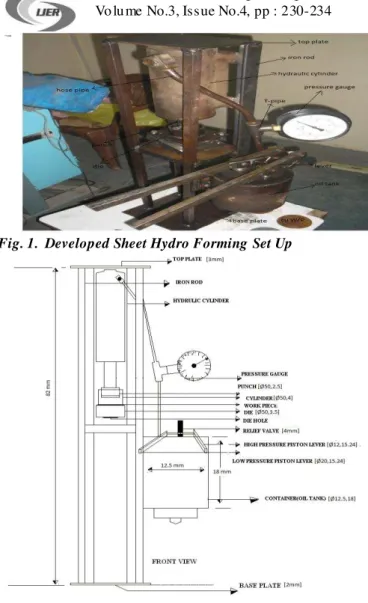
Fig. 1. Developed Sheet Hydro Forming Set Up
Fig. 2. Schematic View of SHF Set up
In this process of set up design and fabrication, at first four rod are taken and arc we lded with base plate in a rectangular shape to hold the whole set up as shown in Fig 1. Fro m base to some height (43mm) a rectangular plate is welded to contain the die set up and to support the blank holder, cy linder etc. The blan k holder and cylinder are further welded to form the complete hydro form set up.
During the sheet hydro forming process, the work p iece or sheet meta l is placed over the die. The blank holder and cylinder combination is placed over the die. The bolts are properly tightened with the die and blank holder. Abov e the cylinder the punch is bolted with the piston of the hydraulic cylinder. The hydraulic piston is wounded by spring in the hydraulic cylinder and it moves by stroke of hydraulic pressure. The punch and piston are connected by bolts. The total hydraulic cylinder is welded on rectangular holding device. Above the hydraulic cylinder the top base plate is welded with a holding device. The container (oil tank) is connected to rectangular holding device by bolts. The container (oil tank) is built by two piston such as high pressure piston and low pressure piston. With this, a relief valve, four ball and threads are arranged inside the container (oil tank).The container (oil tank) and hydraulic cylinder are connected by a T-pipe through which oil flo ws during the sheet hydro forming process.
In the middle portion of the T-pipe, the pressure gauge is connected to measure the hydraulic pressure during the process.
The fluid is poured through the relief va lve .The re lie f valve is connected to the container (oil tank) by ball and thread. In this e xperimental work, Mobile oil was used as working fluid. In order to collect the oil fro m the container, there is bolt connected to the bottom of the container placed. In this set up, two rods are connected to oil tank (container), one is high pressure piston lever and another is low piston lever.
In this work, oil pours into the container by removing the relief valve, the relief valve is closed. After closing the relief valve, pressure gauge is connected to T-pipe. The work piece is placed over the die, then cylinder and blank holder arrangement are placed over the work piece. Oil is poured into the cylinder, then low pressure piston lever of the container (oil tank) or high pressure piston lever which is connected to rod outside the container is moves up and down. By the move ment of the piston inside the container, the oil is pressurized and it rises through the T-pipe. Then the pressurized oil goes to the hydraulic cylinder and then moves the spring wounded piston downward.
The punch which connects to piston of hydraulic cylinder also moves downward and it applies pressure on the oil of the cylinder, then the oil provides the uniform pressure on the work piece (sheet) and the work p iece deform under the ap plication of hydraulic pressure. At the same time pressure reading is recorded by the pressure gauge. After deformation of the work piece, the required product is removed and the oil above the product also re moved. During the process proper cla mping, positioning of the work piece and pressure gauge are very essential. In this work, hemispherical products of the sheet metal have made. The alu min iu m and copper have used as work piece and Mobile oil as flu id mediu m.
3.0 Result an d D is cus sion s:
To carry out e xperiments on the fabricated setup, two types of job materia ls are used for diffe rent set of the experiments for cup shape products. Several e xpe riments are carried out on th e fabricated SHF setup (Fig 1) with Alu min iu m and Copper work pieces. Tooling material, Dies and clamp ing devices are also suitably selected as required as the integral part of the setup.
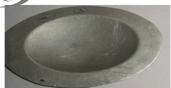
Both Aluminiu m and Copper (Fig 3 and 4) are used as the job (work piece) to get the desired shape product. The mechanical and physical properties of both Alumin iu m and Copper used are taken into consideration using electron scan microscopes. Fig 4 shows the deformed Alu miniu m work on the setup. Fig 5 shows the Copper work pieces of two different thickness es and Figure 6 shows the corresponding deformed pieces on the setup. Fig 7 and 8 shows the failed p ieces due to improper b lank ho lding force and high stain rate applications.
IJER@2014
Page 232
Fig. 4: De formed piece through the SHF setup.
Fig. 5: Copper work pieces
Fig. 6: De formed one on the setup.
Both Alu miniu m and Copper sheet are used in this work by using blanking process. In this process Aluminiu m/ Copper pieces were deformed to get the required wo rk piece as per the die (hemispherical die ). The thickness of the work pieces (Al/Cu) are taken into consideration. In case of sheet metal, it is very d ifficult to resist the transverse load. The thickness is considered in mm and it varies for A lu miniu m and Copper e xperiments.
A Matlab based artific ial neural network (A NN) toolbo x was used for prediction of dome height of alumin iu m and copper piece after applying hydraulic pressure. Experimental data was used for train ing and testing of ANN.
Three parameters (thickness, diameter and applied pressure) as input and dome height (DH) as target of aluminiu m and copper plate were used for train ing of ANN. Eighty percent data were used for training of ANN. Re ma in ing twenty percent data were used for testing of ANN.
Figure 7 shows the architecture of ANN. Th is ANN a rchitecture contains two hidden layers (containing 6 and 2 neurons respectively) and one output layer (containing 1 neuron).
Fig.7: Feed forward architecture of a neural network.
Figure 10 and 11 shows the linear regression analysis between observed and simulated do me height for a lu min iu m and copper sheets respectively. The linear reg ression analysis committed for good result for prediction of dome height by ANN after applied hydraulic pressure for both aluminiu m and copper sheets. The regression analysis showed coefficient of determination (R2) for alu min iu m was .99732 and for copper .94997.Therefore , the ANN best suitable for predict ion of dome height of alu min iu m sheet than copper sheet.
Fig. 8 and 9 showing failure of alu miniu m wo rk piece due e xcessive axial load or blank ho lding force. Hence by applying appropriate hydraulic pressure these mode of failures can be avoided.
Fig. 8: Wrinkling and tearing of Aluminium work piece
Fig. 9: Wrinkling and Bursting of Aluminium work piece.
IJER@2014
Page 233
instantaneous geometry of defo rmed sheet during deformat ioncan be analytically e xpressed.
Fro m the experimental wo rk, it shows that the deformed hemispherical part of work p iece depends on the thickness of work piece, young’s modulus and velocity of the punch. It also leads to the failure para mete rs of the hemispherical product.
To calculate the required a xial load(Fa ) which applies on the flu id mediu m, area o f fluid contact to the work p iece are considered as per experimental setup blank holding force(Fb), sealing force, friction force (Ff) a re a lso taken into consideration.
Total force = a xia l force + blan k holding fo rce+ friction force
F= Fa + Fb + Ff ...(1)
In above equation, the blank holding force (Fb) and friction force (Ff) assumed to be neglected for the estimat ion of a xia l force (Fa) acting on the circular sheet. The required hydraulic pressure are directly measured fro m pressure gauge mounted on the e xperimental SHF setup.
Axia l load= hydraulic pressure(p) x area upon which the hydraulic pressure is acting
Fa= p x A...(2)
With the help of equation (2) a xial force can be easily calcu lated.
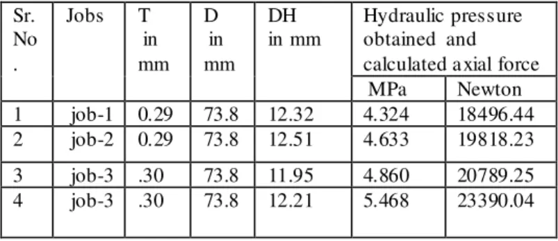
Table 1 Expe rimental result of Alu miniu m work p iece during SHF
Sr. No
Job T in mm
D in mm
DH in mm
Hydraulic pressure obtained and calculated a xial force
MPa Newton
1 job-1 0.41 73.8 7.73 2.316 9906.97 2 job-2 0.41 73.8 7.78 2.779 11887.50 3 job-3 0.42 73.8 6.44 3.088 13209.32 4 job-4 0.42 73.8 6.92 3.861 16515.90 Least count=0.1ton/in2
Table 2 Expe rimental result of copper work piece during SHF
Fig. 10: Linear regression of ANN simulated Dome Height (DH) and experimetal Dome Height (DH) data for Alluminium work piece.
Fig.11: Linear regression of A NN simulated Dome Height (DH) and experimetal Dome Height (DH) data for Copper work piece.
4. 0 C o nc lus ion
A manually working SHF setup has been fabricated to work hydraulically for the analysis of sheet hydro forming process in IIT BHU. After fabricating and establishing the required parameters for e xperimental work, the setup is used to calculate the hydraulic pressure needed for deforming of he mispherical (cup shape) product. Based on the pressure gauge reading and desired hemispherical product, it is possible to form hemispherical with hydraulic pressure. The calculated pressure profile shown by the setup is good; sometimes it turns to be high causing sheet to fracture and wrinkle free (Fig 7& 8).
The cause of wrinkling is attributed to the error in the pressure gauge used in the experimental set up. It is shown that, hydraulic flu id pressure cause the deformat ion to the sheet in the flange area and therefore pushing the strain above the wrinkling limit []. In the setup there is provision for change of applied load, selection of materia l and pressure gauge for new and future developments in the setup.
Sr. No .
Jobs T in mm
D in mm
DH in mm
IJER@2014
Page 234
Due to the uniform deformation of work piece the dent resistanceof hydroformed part improves and tendency of tearing reduces due to free bulging compare to conventional stamping processes. Out of these advantages the main advantage of sheet hydroforming process is the greater range of pre- instability strain obtainable.
The critica l hydroforming parameters can be easily predicted using ANN model because of its accuracy and simplicity.
A c kn o w led g e me nt
The authors gratefully acknowledge Professor Santosh Kumar, Depart ment of Mechanical Engineering at Indian Institute of Technology B.H.U (Va ranasi). Bholanath Viswaka rma, Dileep ku mar Gupta,(Research Scholar Department of Physics at Indian Institute of Technology B.H.U.) for their valuable guidance &co-operation.
R ef e r e nc e s:
i. .O. Kreis, P. Hein “ manufacturing system for the
in t eg r at ed h yd r o f o r mi n g , t ri mmi n g a n d w el d i n g o f s h eet met a l
pair” j. Of ma t p r o c a n d t ech .1 1 5 (2 0 0 1 ) 4 9 -5 4 .
ii . . S h i -Hong Z hang et al “technology of sheet
hydroforming with a moveable female die” inter. Nat j. Of mac.
T o ol a n d ma n u . 4 3 (2 0 0 3 ) 7 8 1 -7 8 5 .
iii . S.H Z hang et al. “ Rec ent development in sheet
hydroforming technology” j. Of mat proc and tech. 151(2004)
2 3 7 -2 4 1 .
i v. Lihue L ang et al. “ Multilayer sheet hydroforming
exp er i men t a l a n d n u mer i ca l i n ves ti g a ti o n i nt o t h e ver y l a yer i n t h e
middle” j. Of mat proc and tech. 170(2005) 524-5 3 5 .
v. .G P a l u mb o et al. “ numerical/experimental
investigations for enhancing thr sheet hydroforming process”
in t er . N at j . Of ma c. T o o l a n d ma n u . 4 6 (2 0 0 6 ) 1 2 1 2 -1 2 2 1 vi . T a ka yu ki Ha ma et .al . “F i ni t e el emen t si mu l at i o n o f th e elli p ti ca l cu p d eep d r a wi n g p r o ces s o f s h eet h yd r of o r mi n g” fi n . El e. In a n l ys a n d d es i g n 4 3 (2 0 0 7 ) 2 3 3 -2 4 6 .
vii . .Ahmed assempour et al. “P r ess u r e esti ma t i o n i n t h e h yd r of o r mi n g p r o ces s of t h e s h eet met a l p ai r s wit h t h e met h o d o f
upper bound analysis” j. Of mat proc and t ech .2 0 9 (2 0 0 9 ) 2 2 7 0
-2 -2 7 6 .
viii . Rosel et al. “improvi n g f o r ma b il it y d u e t o a n en h a n ce men t ca u s ed b y us i n g a s ma rt fl u i d as a ct i ve med i u m f o r
hydroforming” prod. Eng. Res. De vel. (2013)
i x. M. A . K a r ko u b et .a l . ''Mo d el li n g Def o r ma t i o n o f Hyd r o f o r med C ir cu l a r Pl at es Us i n g N eu r a l N et w o r ks'' Int J A d v Ma n u f T ech n o l (2 0 0 2 ) 2 0 :8 7 1–8 8 2
x. F o r o u h a n d eh et .al . ''De vel o p men t of s h eet h yd r o -fo r mi n g s et u p a n d p r o d u ct ch a r a ct eri z at i o n'' 4th i n t er n ati o n a l a n d 2 5th A ll In di a ma n u f a ct ur i n g t ech n o l o g y , d esi g n a n d r es ea r ch co n f er en ce(A I MT D R 2 0 1 2 )
xi . F a u s ett , L .:” Fundam entals of neural networks.” P r en ti ce Ha l l P u b li s hi n g , N ew Y o r k (1 9 9 4 )