Evaluation Of Air Separator For Processing
Particulate Chemical Industry Gas Streams
F. W. Ntengwe, M. Chanika
ABSTRACT: The evaluations of an air separator for processing chemical engineering particulate gas streams was carried out with a view to investigate the performance for different flow rates and other characteristics. A louver (LV) air separator was used as a case study. The evaluations indicated that for various set points of characteristics, the prediction of operating efficiencies could be made for different variations of louver gap (LVG) with area ratio (AR), length of separator at particular angles of LV inclination and the number of LV with flow rates. It was observed that efficiencies ranging from 40 to 60%, on one hand, were obtained for high values of LVG and gas flow rate. On the other hand, efficiencies of 61 to 99% were obtained for lower values of LVG and gas flow rate. It was noted therefore that in order to produce high efficiencies, the values of LVG and flow rates have to be low and vice versa. The evaluation indicates also that plant operators can quickly predict, from the results, the operating efficiency for the desired dimensions and or flow rates of particulate gas streams. The methodology for the determination of operating data can be used in minimum-time frame to optimize the operations of the plant.
KEYWORDS: Air-separator, Performance, Characteristics, Evaluation, Efficiency, Particulate, Engineering, Processes
————————————————————
1.0 INTRODUCTION
Air separators are used to capture particulate matter from air or gas streams that are fed to or discharged from process plants [1], [2], [3]. They are normally situated before or after the processing plant with a view to providing clean air or gas stream to and from the process plants in order to prevent consequential blocking and damage [4], [5]. They are used in gas turbine engines, crushing plants and other chemical engineering processes to make the environment sustainable and other physical operations that release particulate matter to the air or gas streams [6], [7]. Different types of air separators have been developed since 1950s [1], [8]. However, literature on the methodologies is not elemental to most plant operators. It is therefore not easy to predict the efficiency of an air separator unless it is coupled to automatic controllers that can provide operating data. It is for this reason that a simple method that generates data and results from which the efficiencies can be predicted is presented. The method begins with a flow balance from which various correlations of characteristics can be obtained that can be used to predict the specific predicted operating data and efficiencies. The purpose of the study was therefore to evaluate the baffle-type or louver air separator [9] to allow the reader or plant operators to determine the baffle gap (LVG) in relation to the area ratio (AR) of the exit ports to the separator and establish the performance efficiency at different flow rates and other characteristics of the desired separator for given operation.
2.0 CONCEPTUAL FRAMEWORK
Air separators are constituted through a design process which is a creative activity that results into product that contributes to solution of or solves community challenges. External and internal constraints are usually considered before the process of making the separator (7). The financial costs and government regulations are some of the external constraints while manpower and methods are some of the internal constraints which must be considered early during the process in order to prevent wastage. The evaluation of an air separator considers the use of the various characteristics that are used in the design process because it is these that bring about the desired correlations that can be obtained during the operation.. The first correlation is the mass and
energy balance which are used as elements of the design of air separators [7]. The conceptual approach is illustrated in figure 1.
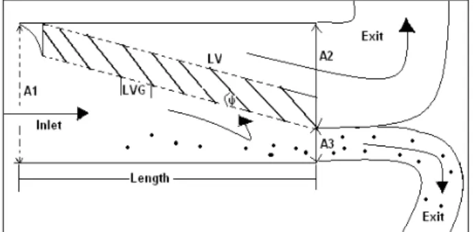
Fig. 1. Design concept of air separator showing louvers, louver angle, louver gap and inlet and exit ports
The flow balance is given by (1) where Q is the flow rate of the gas stream (m3s-1). The mass balance is given by (2)
where ρ is the density of the gas streams (kgm-3). The constitution of the air separator begins by linking the flow rate of the gas stream to the dimensions of the inlet and outlet ports of the unit to provide the mass balance as given by (3) where A is the area (m2) and V is the velocity of the gas stream (ms-1).
3 2 1
Q
Q
Q
(1)3 3 2 2 1
1
Q
Q
Q
(2)3 3 3 2 2 2 1 1
1
V
A
V
A
V
A
(3)For low concentrations of particulate matter in gas streams the density of particulate matter can be considered to be uniform for both the inlet and outlet streams and the flow velocity of gas (Vg; ms
-1
) is given by (4) while the residence
time ( ; s) by (5) where Dc is the chamber diameter (m) and
3 3 2 2 1 1
A
Q
A
Q
A
Q
V
g
(4)1
D
cu
o
(5)3.0 METHODOLOGY
3.1.0 Sizing of the separator
The sizing of the air separator was carried out by determining the length, height and diameters of the outlet ports to give the AR values, the louver length and width for a particular angle of inclination.
3.1.1 Length and height of air separator
The separator length (X; m) was determined using (6) where
δ is the LVG (m), ψ is the angle of LV inclination and NLV is
the number of LV while the height or diameter of the separator chamber (Dc; m) was determined using (7) where
d2, the diameter of the upper port, and d3, the diameter of the
blow-down port, are the exit ports from the separator (m).
(cos
)
1N
LVcos
X
(6)
3 3
2
d
N
sin
d
d
D
c
LV
(7)3.1.2 Area ratio
The value of AR was calculated using the diameters of exit ports as given by (8) where H is the height (m) of the separator chamber
}
sin
/{
}
sin
{
1 32
d
N
LV
H
N
LV
d
AR
(8)3.1.3 Width and length of louvers
The width of LV (L; m) is given by (9) while the length is given by either the chamber diameter in the case of cylindrical air separators or the width of the separator in the case of box-type separators.
LVcos
g
N
V
L
(9)3.1.4 Dimensional correlations
Many correlations were explored in order to determine the variations of dependents with independents. The purpose of such exploration was to generate information that plant operators and engineers can use when handling different types of air separators and louver-type separators in particular. The correlation included: Number of LVs for given AR and louver gap, size of LVG for given AR and Number of louvers, area ratio for given number of LVs and louver gap, size of LVG for given length and number of louvers, number of LVs for given length and louver gap and length of separator for different LVGs and number of louvers.
3.2.0 Performance evaluation
3.2.1 Separator performance
The performance evaluation was meant to determine the optimum conditions of the separator prior to plant operation or during operation. It was meant to be a guide to the
engineers or plant operators either during the construction process of plants or process monitoring to be mindful of the limits that have been theoretically developed. The evaluation used key independent characteristics such as length of separator, AR, number of louvers (LV), flow rate etc which were set to determine the variation of dependents such as efficiency in single dimensional analysis. The two dimensional efficiency analyses have been dealt elsewhere [11]. The trends of data were evaluated using exploration method in excel [12], [13].
3.2.2 Evaluation of separator efficiency
The efficiency ( ; %) was determined from (10) at particular
values of independent variables. Efficiency calculations were carried out for each LV angle, LVG, AR, number of LVs and gas stream flow rate as independents.
}
/
{
1
Exp
u
oA
1N
LVQ
1
(10)4.0 RESULTS
4.1 Number of LVs for given AR and louver gap
The results in figure 2 show the variation of AR, LVG and LV at 20o louver angle. They can be used to determine the number of LV for given AR and LVG. By knowing two of the variables, AR and LVG then LV can be determined. It is noted also in the same graph that increasing the LV decreased the louver gap. For a particular value of AR, increasing the LVG resulted in the decrease of the LV value. For example, at AR of 4 and LVG of 0.03 the LV was 20. But when the LVG increased to 0.05 the LV of 12.5 was obtained. Therefore the increase of LVG at fixed value of AR reduced the number of louvers. Therefore, the number of louvers could be determined from the known values of LVG and area ratio.
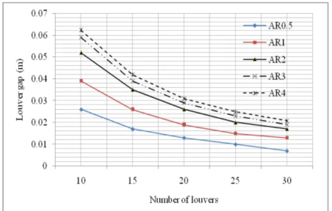
4.2 Louver gap for given AR and number of louvers
For given LV and AR, the LVG can be determined from correlations. The results in figure 3 show the variation of LVG, LV and AR at 30o angle of inclination. Increasing the number of louvers at a particular value of AR decreased the LVG value. At AR of 8 and LV of 10 (LV10) the LVG was 0.132. However, when the LV increased to 20 (LV20) at constant AR, the LVG was 0.064 which was lower than that at LV10. Therefore, the method was useful in determining LVG for given AR and number of LV at particular LV angle.
4.3 Area ratio for given LVs and louver gap
Fig. 2. Determination of the number of LVs for given AR, LVG and LV angle
Fig. 3. Determination of the size of LVG for given AR, number of LV and LV angle
The LVG values for LV10 were higher than those for LV20 and LV30 indicating that the higher the number of LV the smaller the LVG required. At fixed values of LV, the values of LVG could be varied in order to set the length and height of the separator through the variation of AR values.
4.4 Size of LVG for given length and number of louvers
The length of the separator can be used as criteria to determine the LVG size. This can be done where the determination of length is carried out first. By setting the values of length and number of LVs, the LVG size can be determined using figure 5 where the results show that an increase in length produces and increase in LVG for any known value of louvers inclined at 20o angle. It can also be observed that increasing the number of LVs does not affect the length of separator. Therefore the LVG is dependent on both the length and the number of LVs for the separator.
4.5 Number of LVs for given length and louver gap
The number of LVs was dependent on the length and LVG of the separator. For given value of length and LVG the number of LVs could be determined from figure 6. For example, for a length of 1 m and an LVG of 0.054 at an LV angle of inclination of 30o the number of LVs was 30 while for the same length and LVG of 0.158 the number of LVs was 10. Therefore the number of LVs can be determined for any
given LVG, length of separator and angle of LV inclination.
4.6 Length of separator for different LVGs and number of louvers
The length of air separator was found to be a function of LVG and number of LVs at a particular angle of LV inclination. The results in figure 7 show that a set of LVG and LV could be used to determine the length of the air separator at 40o angle of LV inclination. If we chose the number of LVs to be 15 and the LVs was 0.2, the length of the separator would be 1.5 m. Therefore, for each set of values of LVG and LV, the length of the separator could be obtained. It was also noted that decreasing the LVG increased the number of louvers but did not affect the length of the separator.
Fig. 4. Determination of AR for given number of LV, LVG and LV angle of inclination
Fig. 5. Determination of LVG for given length of air separator at 20o LV inclination
Fig. 6. Determination of number of LV for given LVG and length of separator at 30o LV inclination
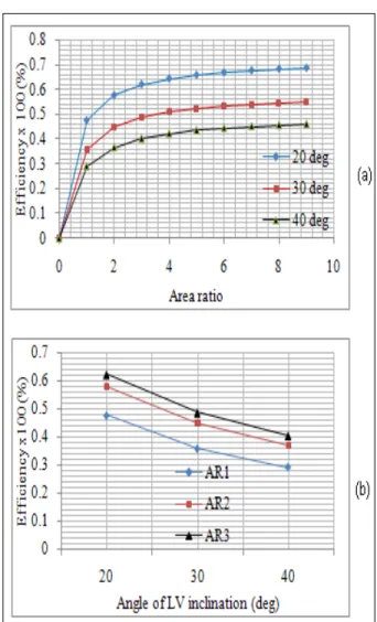
4.7 Effect of angle of LV inclination on the separator efficiency
The results in figure 8 (a) show that the efficiencies at 20 deg angle of LV inclination were higher than those at 30 and 40 deg respectively at gas stream flow rate of 1000 m3/h and 0.06 louver gap. This was demonstrated by the curve for the 20 deg angle which was above that of 30 deg angle which was also above that of 40 deg angle. The results further demonstrated that higher separator efficiencies (>50%) could be obtained when the angle of LV was smaller (<30 deg) than that when the angle was large (>40 deg). The highest and lowest efficiencies at 20o LV angle were 62 and 47.6% respectively at AR3 while the highest and lowest efficiencies at 40o LV angle same AR were 40.25 and 29.1% respectively as shown in Figure 8 (b). A similar trend was observed at AR1 and AR2 meaning that increasing the angle of LV decreases the efficiency of the separator.
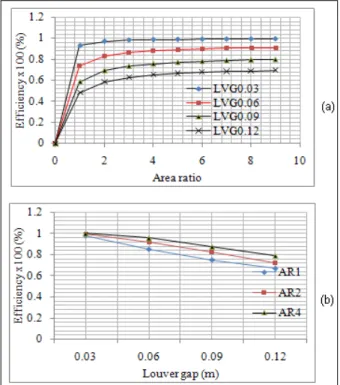
4.8 Effect of LVG on the separator efficiency
In figure 9 (a), different levels of efficiencies were obtained for different values of LVG at a particular value of AR, 30o angle of LV inclination and flow rate of 500 m3/h. The values for LVG0.03 were higher than those for LVG0.06 which were higher than those of LVG0.09 which were higher than those of LVG0.12 (
LVG0.03
LVG0.06
LVG0.09
LVG0.12). For example, at AR 6, the efficiency of the separator was found to be 98.9, 89.5, 77.7 and 67.7% for LVG0.03, LVG0.06, LVG0.09 and LVG0.12 respectively. Therefore, at any value of gas flow and AR, the separator efficiency was found to be dependent on the size of the louver gap. The results in Figure 9 (b) show that the increase in LVG produced a decrease on the efficiency of the air separator at 20o angle of LV inclination. This means that the wider the gap between LVs the lower the efficiency of the separator. It could also be seen that LVG of 0.03 produced higher efficiency for AR1 (97.8%) than LVG of 0.12m (67%) at the same area ratio. A similar trend was observed for AR values of 2 and 4 respectively.4.9 Effect of AR on the separator efficiency
When the AR was varied, the separator efficiency varied also. When the AR increased, the efficiency increased. The results in figure 10 show that when AR increased from 1 to 4 at LV angle of inclination of 40o, the efficiency of the
separator increased from 97.8 to 99% at LVG0.03, 72.5 to 87.3% at LVG0.06, 61.3 to 78.1% at LVG0.09 and 54.1 to 71.3% at LVG0.12 respectively. Therefore the efficiency of the separator
Fig. 7. Determination of length of separator for given LVG and number of LV at 40o LV inclination.
Fig. 9. Effect of LVG on separator Efficiency at (a) 30o LV angle and (b) at 20o LV angle at flow 500 m3/h
Fig. 10. Effect of AR on the efficiency for different LVGs at 40o LV angle and air flow of 500 m3/h
Fig. 11. Effect of LVs on the separator efficiency at 20o LV angle, a height of 0.5 m and flow of 500 m3/h
was found to be dependent on the AR for given LVG and of LV inclination and flow rate of gas stream.
4.10 Effect of number of LVs on the separator efficiency
For given LVG the increase in LV produced an increase in efficiency at 20o LV angle and flow rate of 500 m3/h. As can be observed in figure 11, the efficiencies at number of LVs of 10 were 92, 76, 65 and 57% which were lower than those at number of LVs of 25 as 99, 97, 93 and 88% at LVG0.03, LVG0.06, LVG0.09 and LVG0.12 respectively and for angles of LV less than 45o (20<30<45o). Therefore, the efficiency of the separator was dependent on the number of louvers.
4.11 Effect of flow rate on the separator efficiency
Allowing theoretical air flow to the air separator at a chosen LVG produced an efficiency that was dependent on such air flow. The results in figure 12 show that different air flows produced different levels of efficiency. For an air flow of 500 m3/h and LVG0.03, the efficiency was found to be 99.8% while a flow of 2500 m3/h produced an efficiency of 72.7% at the same louver gap. Similarly, for a flow of 1500 m3/h and LVG0.09, the values of efficiencies were 48% while the efficiency at 2000 m3/h at the same LVG was 41% which was different. It was also noted that as the air flow rate increased by 2000 m3/h, the separator efficiency decreased by 27.1% at LVG 0.03 m, 48.2% at LVG 0.06 m, 52.8% at LVG 0.09 m and 54.1% at LVG 0.12 m. The greater the decrease in efficiency, the lower is the level of efficiency. Therefore, increasing the air or gas stream flow rate decreased the separator efficiency.
5.0 DISCUSSIONS
It has been shown in this study that the LV angle contributes to the efficiency of the air separator. If one has to decide on what angle to design the LVs then the results in this study clearly show how a choice can be made based on the level of efficiencies attained by each angle. Since the angles <30o gave higher efficiencies, it would not be prudent for the designer or engineer to choose angles >30o as these would give lower efficiencies due to the fact that the LVs would not hinder the flow adequately because such angles do not allow the gas stream to have adequate change of direction to allow the particles to fall off and go with the air to the blow down port or allow the particles to be collected in the particles chamber. The LVG contributes to the number of LVs, the length of the air separator and hence the efficiency. It has been shown
in this study and elsewhere [10] that the smaller the LVG the higher the number of LVs that an air separator can have and hence the higher the efficiency. It is important therefore to provide as small an LVG as is possible in order to accommodate as many LVs as possible in order to increase the theoretical efficiency. The LVGs <0.06 have been found to give higher efficiencies than those >0.06 value. It is therefore important to trade off between LVG and size of air separator in order to operate within optimum conditions of right LVG, AR, number of LVs, angle of LV inclination and efficiency. The area ratio of the exit ports of the separator is one of the critical factors in the design and performance evaluation of the air separator. Because of the area ratio, it has been possible to determine the dimensions of the exit ports and evaluate the efficiency of the separator. Since large area ratios gave higher efficiencies, it shows how important it is to make the blow down area of the exit port as small as possible in order to optimize the design and maximize the separator efficiency. The number of LVs, as alluded to earlier, is linked to the size of LVG and length of the separator. When the LVG is fixed, one can increase the number of LVs and vice versa. Increasing the number of LVs increased the efficiency. Therefore designers and engineers engaged in product development and modifications need to consider such correlations before, during and after design, installation and commissioning of chemical engineering plants. It has been shown in this study that theoretical efficiencies can be obtained without knowing the concentration of particulate matter in any process change [14]. Efficiencies above 80% for flows <500 m3/h mean that it
is pointless to run the air separator on gas streams that have flow rates above 1000 m3/h because most of the particles would not be able to settle due to the change in direction of gas stream in the separator. However, the general picture of the results for the efficiencies based on flow rates or velocity is that a choice of the flow rate and LVG can be made prior to operation based on the theoretical results [15].
6.0 CONCLUSION
The increase in LVG produced a decrease in separator efficiency and vice versa at any given-gas flow rate. The increase in number of LVs produced an increase in separator efficiency for any angle of inclination (20<30<40o) and any flow rate. The lower the angle of LV inclination, the higher is the separator. Also, the increase in gas stream flow decreases the separator efficiency. Therefore the operations of air separators should be at lower gas flow rates and lower LVG in order to obtain maximum benefit.
REFERENCES
[1] C.W. HARWELL, “An Initial Study of a Louvre-Type Dust Separator”, M. Sc. Thesis, Georgia Institute of Technology, 1950.
[2] A.P. SCHWEITZER, “Hand Book of Separation Techniques for Chemical Engineers”, 3rd Ed., McGraw-Hill Book Company Inc., Oxford, 1997.
[3] Y.S. Chen, S.S. Hsiau, S.C. Lai, and Y.P. Chyou, et al., “Filtration of Dust Particles With a Moving Granular Bed Filter”, J. Hazard Mater, vol. 171, no. 1-3, pp. 987-94, 2009.
[4] O. Schneider, F.K. Benra, H.J. Dohmen, and K.
Jarzombek, “A Contribution to the Abrasive Effect of Particles in a Gas Turbine Pre-Swirl Cooling-Air
System”, Gas Turbines, pp. 2005-68188, 2005.
[5] N.D. Caldwell, A.K. Thole. and S.W. Burd,
“Investigation of Sand Blocking Within Impingement and Film Cooling Holes”, Gas Turbines, pp. 2008-52351, 2008.
[6] O. Schneider, H.K. Dohmen, and A.W. Reichert, “An Experimental Analysis of Dust Separation in the Internal Cooling-Air System of Gas Turbines”, Gas Turbines, pp. 2002-30240, 2002.
[7] J.M. Coulson, J.K. Richardson, and R. K. Sinnott,
“Chemical Engineering: An Introduction to Chemical Engineering Design”, Pergamon Press, New York, pp. 1-6, 351-362, 1983.
[8] C.M. Matheson, “A Two Dimensional Study of a Louvre-Type Dust Separator”, M. Sc. Thesis, Georgia Institute of Technology, 1952.
[9] J.C. Bai, S.Y. Wu, A.S. Lee, and C.Y .Chu, “Filtration of Dust in a Circulating Granular Bed Filter with Conical Louver Plates (CGBF-CLPs)”, J. Hazard Mater, vol. 142, no. 1-2, pp. 324-31, 2007.
[10]O.G. Musgrove, D.M. Barringer, E. Gorover, G. Barker and A.K. Thole, “Computational Design of a Louvre Particle Separator for Gas Turbine Engines”, In: Proceedings of ASME Turbo Expo 2009 and Gas Turbines, pp. 2009-60199, 2009.
[11]J.C. Bai, S.Y. Wu, and A.S. Lee, “Dust Collection Efficiency Analysis in a Two-Dimensional Circulating Granular Bed Filter”, J. Air Waste Assoc., vol. 56, no. 5, pp. 684-94, 2006.
[12]J. Tukey, “Exploratory Data Analysis”, Addison -Wesley, 1977.
[13]P. Velleman, and D. Hoaglin, “The ABCs of EDA: Applications, Basics and Computing of Exploratory Data Analysis”, Duxbury, 1981.
[14]A.H. Rose, D.G. Stephane and R.L. Stenburg,
“Prevention and Control of Air Pollution by Process Changes or Equipment”, pp. , 1961.
[15]S.L Alderman, M.S. Parsons, K.U. Hogancamp and C.A. Wagonner, “Evaluation of the Effect of Media Velocity on Filter Efficiency and Most Penetrating Particle Size of Nuclear Grade High-Efficiency