American Journal of Engineering Research (AJER)
e-ISSN : 2320-0847 p-ISSN : 2320-0936
Volume-03, Issue-07, pp-23-27
www.ajer.org
Research Paper Open Access
Circuit Averaging for Boost Converter Involving Generation of
Pseudo-Random Carrier Modulation via PSIM
Anant Kumar Verma, Dr. Gagan Singh
(ELECTRICAL ENGINEERING DEPARTMENT, DIT university, Dehardun, INDIA) (ELECTRICAL ENGINEERING DEPARTMENT, DIT university, Dehardun, INDIA)
Abstract: - The paper reflects the approach towards the understanding of the circuit averaging method used for the power converters. Various software simulation packages are available for the purpose to be served such as MATLAB (Simulink), LTspice, PSIM (power electronics, motor drives, and dynamic system simulation) etc. A mathematical analysis is done for modeling the Boost converter (Step-Up) ideally as well as practically. An implementation of the Pseudo-random carrier modulation scheme is worked on the software package PSIM. Semiconductor devices used in power electronics systems(PES) increases the effects of audible switching noise, electromagnetic interference etc, which is one of the major concern while designing the power converters.
Keywords: - Boost converter, system modeling, MATLAB (Simulink), LTspice, Pseudo-random carrier.
I. INTRODUCTION
In power electronics Boost converter is the basic topology under DC–DC converter, whose behavior serves to convert a DC input voltage to a Higher DC output voltage, which has been widely used in engineering. It is an important step for designing of a Boost converter is to model and analyze this converter according to the real requirements. Many appropriate models have been made by researchers to establish and explore the corresponding analysis method. Up to now, a few good models have been proposed to describe the Boost converter, and a few good analysis methods have been explored to investigate the dynamic behavior.[1] For example, under the assumption that the switching frequency is much higher than its characteristic frequency, the averaged model, which is used to derive the small signal model, can be obtained by averaging the circuit variable within each switching cycle to describe the dynamic behavior of the Boost converter in the low frequency region.[1-2] Controller design for any system needs knowledge of system behavior. Usually involves a mathematical description of the relation established for inputs to the process, state variables, and output. When system is described in the form of mathematical equations which gives an insight behavior of the system (process) is called model of the system. This paper describes an efficient method to learn, analyze and simulation of power electronic converters, using Averaged models. The MATLAB (Simulink), LTspice, PSIM software packages are used to simulate power converters. Our study aims at development of the model for basic converters and studying its open loop behavior, so this model can be used in case of design of any closed loop system. The averaged model can be obtained by using the state-space averaging[2] or the circuit averaging technique.[3] Since the circuit averaging technique, whose advantages are its simplicity and clearer insight into the converter behavior, is applied to derive the transfer functions of the open-loop Boost converter operating in the either continuous conduction mode (CCM) or Discontinuous conduction mode(DCM) of operation .
II. BOOSTCONVERTERMODELING
Fig. no.1. Schematic diagram of a boost converter.
The boost converter of Fig. no. 1 with a switching period of „T‟ and a duty cycle of „d‟ is given. Again, assuming continuous conduction mode of operation, the state space equations when the main switch is ON are shown by,
1
( )
, 0 , :
1 ( ) L in o o di V dt L
t dT Q ON
dv v
dt C R
(1)
Fig. no.2. when Switch is ON and when the switch is OFF
1 ( ) , , : 1 ( ) L in o o o L di V v
dt L dT t T Q OFF
dv v
i
dt C R
(2)
Fig. no. 3. when Switch is OFF
III. RULESANDCIRCUITAVERAGING There are three important RULES in learning power electronics converters [4]: Inductor Volt-sec balance.
Capacitor charge balance. Small ripple Approximation.
Under steady-state conditions power converter output response is periodic in nature and hence rather applying Fourier analyses to the output waveforms. It is best suited that we should apply these rules in steps so as we can easily apply our conventional KVL and KCL rules in a simpler manner.
1. Inductor volt-sec balance:
<��>=1
� ��(�) �
�
0
2. Capacitor charge balance:
<� > =1
� � � �
�
Fig. no.4. Small ripple approximation.
4. Averaging of the boost converter obtained in two states of switch Q:
So to make our implementation easy and simpler we take an average of the equations sets 1 and 2 with respect to the duty ratio d.
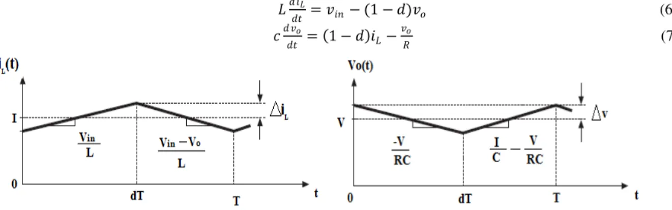
� ��
� =�� −(1− )� (6)
�
� = 1− ��−
�
� (7)
Fig. no.5 Behavior of inductor current and output voltage switch Q changes its ON state to OFF state.
Hence ,we are able to predict the response of the boost converter on the above basis in a simpler manner. Averaged switched model has been made in LTspice for analysis of the converter ratio which gives relationship between output voltage and input voltage.(here switch is the averaged model of the semiconductor devices)
= �
�� =
1
1− (8)
Fig. no.6 Converter ratio K changes as duty ratio changes with respect to Vin=10v ,R=10,C=2.5mh,L=4mh.
IV. GENERATIONOFPSEUDO-RANDOMCARRIER
Fig. no.7 Steady-state and transient analysis of a boost converter using Pseudorandom carrier and DC-signal as reference.
Fig. no.8. Implemented open loop boost converter using PSIM.
Fig. no.9. Internal block S1 and S3 for implementation of PSEUDO-RANDOM-CARRIER.
ZERO DEGREE PHASE SHIFT 180 DEGREE PHASE SHIFT
Fig. no.10 Generated Pseudo-random Carrier using PSIM.
REFERENCES
[1] Kazimierczuk M K , Pulse-width Modulated DC–DC power converters (London: John Wiley and Sons, 2008).
[2] Zhang W P ,Modeling and Control of Switching Converter (Bejing: China Electric Power Press, 2006). [3] Tse C K ,Complex Behavior of Switching Power Converters (New York: CRC Press, 2004).
[4] R.D. Middlebrook, “Topics in Multiple- Loop Regulators and Current-Mode Programming” IEEE PESC Proceedings, June 1985.
[5] Joachim Holtz, “Pulsewidth Modulation- A Survey”, IEEE Trans, Industrial electronics, Vol. 39,no.5,December 1992.
[6] Anant Kumar Verma, A Distinct Pseudo-Random Carrier Modulation Approach for a Boost Converter, IEEE conference on Communication Systems and Networks Technology,Bhopal,INDIA,2014.
[7] Sun J, Mitchell D M, Greuel M F. Averaged modeling of PWM converters operating in discontinuous conduction mode[J]. IEEE Trans. Power Electron, 2001, 16(4): 482-492.
[8] Muhammad H. Rashid, Power Electronics- Ciruits, Devices, andApplications( 9th edn., New York ,Springer-Verlag, , 2011).
[9] N. Mohan, T. M. Undeland, W. P. Robbins, Power Electronics: Converters, Applications, and Design