V. Tita, J. de Carvalho and
J. Lirani
Dept. of Mechanical EngineeringUniversity of S. Paulo 13560-250 S. Carlos, SP. Brazil [email protected], [email protected],
Theoretical and Experimental
Dynamic Analysis of Fiber Reinforced
Composite Beams
The composite materials are well known by their excellent combination of high structural stiffness and low weight. Their inherent anisotropy allows the designer to tailor the material in order to achieve the desired performance requirements. Thus, it is of fundamental importance to develop tools that allow the designer to obtain optimized designs considering the structural requirements, functional characteristics and restrictions imposed by the production process. Within these requirements, this work considers the dynamic behavior of components manufactured from fiber reinforced composite materials. To this end, some beams were made using the hand-lay-up process followed by a molding under pressure and heating. Experimental dynamic tests were carried out using specimens with different fiber orientations and stacking sequences. From the results, the influence of the fibers orientations as well as the stacking sequences on the natural frequencies and modal damping were investigated. Also, these experiments were used to validate the theoretical model and the results obtained from the finite element analysis.
Keywords: Composite materials, finite element method, modal analysis, vibrations
Introduction
Since many years ago, the combination of different materials has been used to achieve better performance requirements. As example of that the Sumarians in 4000 B.C. used to add straw to the mud to increase the resistance of the bricks (Ansys User's Manual, 1995). Although the benefits brought by the composite materials are known for thousands of years, only some years ago the right understanding of its behavior as well as the technology for designing composites started to be developed. The airplane F.111 was one of the first models to incorporate this technology. As another example, the airplane Boeing 767, has 2 tons in composite materials (Tsai, 1986). The possibility to combine high strength and stiffness with low weight has also got the attention of the automobile industry: the Ford Motor Company developed in 1979 a car with some components made from composite materials. The prototype was simply 570 kg lighter than the version in steel, only the transmission shaft had a reduction of 57% of its original weight (Dharam, 1979). More recently, Chrysler developed a car completely based on composite materials, known as CCV (Composite Concept Vehicle). 1
Besides these examples in the aeronautical and automobile industry, the application of composite materials have been enlarged, including now areas as the nautical industry, sporting goods, civil and aerospace construction as shown in Umekawa and Momoshima (1992). In order to have the right combination of material properties and in service performance, the dynamic behavior is one of the main points to be considered. To avoid structural damages caused by undesirable vibrations, it is important to determine:
1 - the natural frequencies of the structure to avoid resonance;
2 - the mode shapes to reinforce the most flexible points or to determine the right positions to reduce weight or to increase damping;
3 - the damping factors.
With respect to these dynamic aspects, the composite materials represent an excellent possibility to design components with requirements of dynamic behavior. Some works as He et al (1993),
Presented at COBEM 99 – 15th Brazilian Congress of Mechanical Engineering. 22-26 November 1999, São Paulo. SP. Brazil.
Paper accepted: July, 2002. Technical Editor: José Roberto de França Arruda.
Koo and Lee (1995) and Eslimy-Isfahany and Banerjee (1997) show applications of these materials to several types of structures. For the Classical Laminate Theory (CLT) the stiffness of the component can be changed according to stacking sequence (Tsai and Hahn, 1980), which allows for the tailoring of the material to achieve the desired natural frequencies and respective mode shapes without changing its geometry drastically or increasing its weight.
Thus, the main objective of this work is to contribute for a better understanding of the dynamic behavior of components made from fiber reinforced composite materials, specifically for the case of beams. In order to investigate the influence of the stacking sequence on the dynamic behavior of the components, experimental and numerical analysis using the Finite Element Method have been carried out. The results are presented and discussed.
Nomenclature
[ ]
M = global mass matrix[ ]
C = global damping matrix[ ]
K = global stiffness matrix{F(t)} = global forces vector
) e ( ] M
[ = element mass matrix
[ ]
N = interpolation functions matrix) e ( ] K
[ = element stiffness matrix
] B
[ = displacement matrix (based on shape functions)
[ ]
D = laminate elasticity matrix (orthotropic case)[ ]
eC = element damping matrix
Greek Symbols
{ }
ä = global displacements vector{ }
ä& = global velocities vector{ }
ä&& = global accelerations vectorρc = composite density r
ù = natural frequency r
}
Materials and Methods
Materials
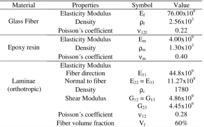
Glass fiber was used as reinforcement in the form of bi-directional fabric (Owens-Corning - Standard E-Glass Fiberglass) and epoxy resin (Ciba Geigy XR-1553) with catalyst addition (HY - 956) as matrix for the composite material. The mechanical properties of the composite were calculated analytically using the simple rule-of-mixtures. More accurate values can be further obtained with some mechanical testing. The values used are shown in Tab. 1.
Table 1. Material properties (International System – SI).
Material Properties Symbol Value Elasticity Modulus Ef 76.00x10⁹
Density ρf 2.56x10
3 Glass Fiber
Poisson´s coefficient ν12f 0.22 Elasticity Modulus Em 4.00x10⁹
Density ρm 1.30x10³ Epoxy resin
Poisson´s coefficient νm 0.40 Elasticity Modulus
Fiber direction Normal to fiber
E11 E22 = E33
44.8x10⁹ 11.27x10⁹
Density ρc 1780
Shear Modulus G12 = G13 G23
4.86x10⁹ 4.45x10⁹ Poisson´s coefficient ν12 0.28 Laminae
(orthotropic)
Fiber volume fraction Vf 60%
Methods
Basically, the work has been developed in three phases:
Production of the laminates specimens
Through hand lay-up process followed by a cure process under pressure, two set of symmetrical laminates with a total of twenty layers each one were produced:
Case1: [45/-45/45/-45/45/-45/45/-45/0/90]s. Case2: [0/90/0/90/0/90/0/90/0/90]s.
After the cure process, the laminate was cut in beams with length of 4.0x10⁻¹m, width of 25.0x10⁻³m, thickness of 1.6x10⁻³m and total mass equal to 28.0x10⁻³Kg.
Modal analysis using the Finite Element Method
Initially the beams were modeled in order to get a first estimation of the undamped natural frequencies and mode shapes. The beams were discretized using fifty finite elements type SHELL99 (Fig. 1), using the commercial package ANSYS (Version 5.2). This element has 8 nodes and it is constituted by layers that are designated by numbers (LN - Layer Number), increasing from the bottom to the top of the laminate; the last number quantifies the existent total number of layers in the laminate (NL - Total Number of Layers). Since each fabric layer corresponds to 2 different fiber orientations (fibers at 0o and 90o), 2 different layers were used to simulate each ply. Abstraction is made of interweaving of the fibers. This assumption does not go against the safety, since it has been proven that this interweaving has positive effects in the final composite performance when intra-ply shear effects are present (Lossie, 1990). Particular cases where this assumption is no longer valid would require corrections in the laminate strength data, as proposed by Tsai (1986).
Figure 1. SHELL 99 (ANSYS User´s Manual, 1995).
The material properties were then entered in the program, and the constraint imposed to simulate a cantilever beam, as shown in Fig. 2.
(a)
(b)
Figure 2. (a) Cantilever beam and (b) Finite Element model (ANSYS).
Once the problem has been discretized, the next step was to find the solution for the general dynamic problem equation:
} {F(t) } ä [K]{ } ä [C]{ } ä
[M]{&&+ &+ = (1)
According to ANSYS Manual User's Theory (1995), the elementary matrices above are calculated by using:
dvol ] N [ ] N [ ] M [ vol T c ) e ( ∫ ρ = (2)
[ ]
D[B]dvol ] B [ ] K [ vol T ) e ( ∫ = (3)[ ]
ν − ν − ν − ν − ν − ν − = − xz yz xy z x zy x zx x yz y x yx x xz x xy x 1 G / 1 0 0 0 0 0 0 G / 1 0 0 0 0 0 0 G / 1 0 0 0 0 0 0 E / 1 E / E / 0 0 0 E / E / 1 E / 0 0 0 E / E / E / 1 D (4)The assembly of the global matrices, next step for the solution of the problem, is done by the package using the equation.
For the determination of the natural frequencies of a undamped system with N degrees of freedom, the solution is sought by solving:
0 } { ] K [ } { ] M
[ NxN δ&&Nx1 + NxN δ Nx1 = (5)
Then,
} 0 { } ]].{ K [ ] M [
[−ùr2 + ör = (6)
Using the procedure described, it was possible to determine the undamped natural frequencies and the mode shapes within 0 and 500 Hz using the Finite Element Method.
Experimental modal analysis
Through an impact experimental test, it was determined the FRFs (Frequency Response Function) which relate the response given by the specimen when loaded with a signal, allowing for the determination of the natural frequencies and the damping factors, as shown in Fig. 3. This was done by fixing the laminate specimen in a rigid support (1) with one of its side free to vibrate, as a cantilever beam. The impact hammer (3) was used to give the input load (pulse) to the specimen, and the Spectral Analyser was set from 0 Hz to 400 Hz. This output was captured by the accelerometer (2) and together with the input sign were amplified (4) using the spectrum analyzer BRUEL&KJAER (B&K) (5), giving the FRF known as accelerance(H(w)) that is given by the acceleration/force relationship.
Previously it was investigated the most attractive points to excite (input) and to get the response (output) in the specimens. Due to their high flexibility it was selected the points 1 (input), 2 and 3 (output) for the determination of two FRFs (H21 e H31), as shown in Fig. 3. Since the specimens are very flexibility and light, special care should be given to choose the accelerometer to avoid undesirable influences on the measurements.
1- Cantilever beam. 2- Accelerometers B&K (Model 4375, Mass =2.4x10⁻³kg) 3- Impact hammer B&K with (piezoeletric cells B&K, Type 8200, Mass =21x10-3kg), 4- Power amplifier B&K 2626, 5- Spectrum Analyzer B&K 2032.
Figure 3. Experimental modal analysis.
After the measurement of the FRFs (Amplitude and Phase), the natural frequencies were evaluated through program FREQ developed by Lirani (1978) and improved by Baptista (1995). Damping factors were estimated through two methods:
1) Peak Amplitude Method of Modal Analysis (Ewins, 1984);
2) Method of Kennedy and Pancu with program FREQ (Lirani, 1978).
Later on, the results obtained by the two methods are compared.
Results
Theoretical and Experimental Modal Analysis
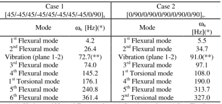
The Table 2 shows the results obtained numerically for the natural frequencies and mode shapes. Figure 4 highlights some mode shapes obtained from ANSYS (version 5.2).
Table 2. Theoretical results from Finite Element Method.
Case 1
[45/-45/45/-45/45/-45/45/-45/0/90]s
Case 2
[0/90/0/90/0/90/0/90/0/90]s.
Mode ωn [Hz](*) Mode ωn
[Hz](*) 1st Flexural mode 4.2 1st Flexural mode 5.5 2nd Flexural mode 26.4 2nd Flexural mode 34.7 Vibration (plane 1-2) 72.7(**) Vibration (plane 1-2) 91.0(**)
3rd Flexural mode 74.0 3rd Flexural mode 97.1 4th Flexural mode 145.2 1st Torsional mode 108.0 1st Torsional mode 176.1 4th Flexural mode 190.0 5th Flexural mode 240.8 5th Flexural mode 313.7 6th Flexural mode 361.4 2nd Torsional mode 327.0 (*) Undamped Natural Frequencies (**) Laminate plane (1-2) – Fig. 2
From theses results it is already possible to verify the influence of the stacking sequence of the laminate: the case 1, with fibers at +/-45o in the external layers, has in general smaller natural frequencies than the laminate of the case 2, with fibers at 0o and 90o. However, when comparing the first mode shape on torsion, the case 1 has a larger frequency than case 2. This was expected, since the natural frequencies are related to the stiffness of the structure and the case 1 (+/-45o) is much more stiffer on torsion than case 2.
The opposite occurs when considering bending loads, the case 2 is stiffer since 50% of the fibers are oriented at 0º, direction appropriate for bending (Flexural Modes).
Table 3 shows experimental results (Fig. 5), as described before. The results show a good agreement with the theoretical values, proving that the stacking sequence has influence on the dynamic behavior of the structure. This was expected since from the Classical Laminate Theory (CLT), the final laminate stiffness is a result of the stacking sequence.
Table 3. Experimental results from FRF.
H21
ωn [Hz]
H31
ωn [Hz] Mode
Case 1 Case 2 Case 1 Case 2
1 4 5 4 5
2 26 28 26 29
3 - - - -
4 74 84 74 83
5 139 155 149 165
6 - - 173 267
7 241 272 246 -
8 348 323 360 395
It is noticed also that the mode shape related to the vibration at plane (1-2) did not appear, since the experimental set up (Fig. 3) does not allow this measurement. Also in some cases, the accelerometer was close to a nodal line making it difficult to get the results. Another point to be noticed was that the expected higher frequency of the case 1 on the mode on torsion did not appear clearly. This may be caused by some influence of the 5th mode (4th flexural mode) on the 6th mode (1st torsional mode), resulting in a combined torsional-flexure mode (see in Tab. 3 that the natural frequencies corresponding to these modes are very close).
Figure 5. Frequency Response Function (FRF) corresponding to H31.
With relation to the deviations of the numeric results in relation to the experimental ones, some possible measurement errors can be pointed out such as: measurement noises, positioning of the accelerometers and their mass, non-uniformity in the specimens properties (bubbles, variations in thickness, non uniform surface finishing). Such factors are not taken into account during the numeric analysis, since the model considers the specimen entirely perfect and homogeneous properties, what rarely occurs in practice. Another aspect to be considered is that the properties input in the model came from the application of the rule-of-mixtures and they do not take into consideration effects of the interface fiber-matrix as well as the irregular distribution of resin on the fibers. Also, the computational package ANSYS (version 5.2) does not allow for the consideration of the fibers interweaving present in the fabric used, as commented before.
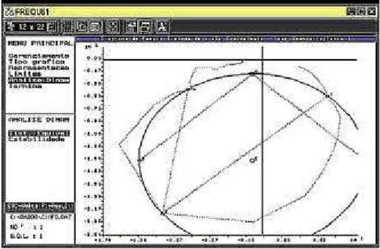
Table 4 shows the structural damping (ζn) and the loss factors (ηn) estimated according to two different methods: Ewins and program FREQ (Fig. 6) for two of the cases studied: torsional and flexural mode.
Table 4. Damping factors.
Case 1 Case 2
Modes and
Methods ηn ζn ηn ζn
3rd Flexural mode ω
n = 75 Hz ωn = 85 Hz Ewins 0.044 0.022 0.025 0.013
FREQ - 0.020 - 0.015
1st Torsional mode ω
n = 150 Hz ωn = 165 Hz Ewins 0.017 0.009 0.012 0.006
FREQ - 0.007 - 0.011
The damping in composite materials derives essentially from the matrix viscoelasticity and from the sliding of the fiber on the interface with the matrix. So, it can be concluded that the cases where the matrix has a more effective dissipativeaction yield to a larger damping factor. Thatis the case as example of the case 1 that has a larger damping factor in the flexural mode than in torsional (the fibers at +/- 45o is more favorable to this loading case reducing the capacity of the matrix to deform and dissipate energy). Similar analysis can be done for other configurations, however, the right understanding (and prediction) of the damping behavior is quite complex and it is beyond the objectives of this work.
Figure 6. Program freq interface.
Conclusion
component, that is, different natural frequencies and damping factor for the same geometry, mass and boundary conditions. This gives the designer one additional degree of freedom to design the laminate - the possibility to change fiber orientations in order to get a more (or less) damped structure. This possibility makes once more these materials very attractive since it makes possible to obtain the desired natural frequencies and damping factors without increasing mass or changing geometry.
The theoretical results from Finite Element Analysis showed in general a good agreement with the experimental values. However, differences appear in some modal shapesindicating the necessity to improve the model input data as well as the experimental procedure. With respect to the model input data, improvements can be made in the material properties data (experimental values instead of application of the rule-of-mixtures) as well as in a more realistic model simulating the interweaving of the fibers in the fabric (the model considered individual unidirectional laminae). Some improvements could be made in the experimental procedure. As for example, by using two accelerometers transversally positioned on the specimen (this strategy would allow more accurate results of the torsional modes), as well as, by reducing the relation of the accelerometer to specimen mass (reducing the accelerometer mass or increasing the specimen thickness).
References
Ansys User’s Manual, 1995, Theory, v.IV.
Baptista, L. H., 1995, “Uma contribuição para a análise da estabilidade contra trepidação de máquinas ferramentas”, MSc. Dissertation, Engineering School of S. Carlos, University of S. Paulo, S. Carlos, S.P., Brazil, 157p.
Dharan, C.K.H., 1979, “Composite materials design and processes for automotive aplications”, Ford Aerospace and Comunications Corporation (Report), California.
Eslimy-Isfahay, S.H.R. and Banerjee, J.R., 1997, “Dynamic response of composite beams with application to aircraft wings”, Journal of Aircraft, Vol.34, No. 6, pp. 785-791.
Ewins, D. J., 1984, “Modal testing: theory and practice”, Research Studies Press Ltd, London.
He, L., Wang, I. and Tang, D., 1993, “Dynamic responses of aircraft wing made of composite materials”, Procedings of the 11th IMAC (International Modal Analysis Conference), Kissimme, Vol. 2, pp.1342-1346.
Huebner, K.H., 1994, “The finite element method for engineers”, J. Wiley, New York.
Koo, K.N. and Lee, I., 1995, “Dynamic behavior of thick composite beams”,Journal of Reinforced Plastics and Composites, Vol.14, pp.196-210.
Lirani, J., 1978, “Substructuring techniques in the analysis of partially coated strucutres”, Ph.D. Thesis, Department of Mechanical Engineering, The University of Manchester Institute of Scienxce and Technology, UK.
Lossie, M., 1990, “Production oriented design of filament wound composites”, Ph.D. Dissertation 90D5, Faculty of Applied Sciences, Division PMA, K.U.Leuven, Belgium.
McConnell, K. G., 1995, “Vibration testing (Theory and Practice)”, J. Wiley, New York.
Tsai, S. W. and Hanh, H. T., 1980, “Introduction to omposite materials”, Technomic, Lancaster.