Vol-7, Special Issue3-April, 2016, pp213-221 http://www.bipublication.com
Research Article
Numerical Simulation of flow in a fishway for investigation of possibility of
inflatable fishway construction
Hesam Mohtasham Amiri*1, Bagher Heidarpour2 and Mehdi Nezhad Naderi3
*1MSc student, Department of Civil Engineering, Tonekabon Branch, Islamic Azad University, and member of young researcher society, P.O. Box 4684161167. Tonekabon, Iran, Tele: +989112268207,
2
Asisstant Professor, Department of Civil Engineering, Roudsar and Amlash Branch, Islamic Azad University, and member of young researcher society, P.O. Box 4684161167. Tonekabon, Iran, Tele: +989112428784,
2
Asisstant Professor, Department of Civil Engineering, Tonekabon Branch, Islamic Azad University, and member of young researcher society, P.O. Box 4684161167. Tonekabon, Iran, Tele: +989112268207
*Corresponding author Email: [email protected].
ABSTRACT
Diversion dams and barriers are considered structures that prevent fish migration along the river. To resolve this problem in the design of dams, hydraulic structures are built as a fishway near the dam. Pool and weir is a type of fishways that make possible migration of fish to upstream of the dam. Velocity, water depth and turbulence are the effective parameters in swimming of fish. In this paper, the three-dimensional equations governing shallow water in weir and orifice fishway are solved with suitable models of turbulence that flow pattern and turbulence can be calculated. The results of simulation of flow were compared with results of field study by Micromollineh. The results show that the turbulence model in numerical simulations can be used as an effective tool for design parameters in pool and weir fishway.
KEYWORDS: Pool and Weir Fishway, Fish Migration, Energy Depreciation, Turbulence Models, Turbulent Flow.
1. INTRODUCTION
Fishway is hydraulic structure that provides fish migration to over natural barriers and dams. Pool and weir is a type of fishways that make possible migration of fish to upstream of the dam. Water flow moves from one pool to another pool. Fish climbs by jumping from a pool to another pool. Pools are separated by the overflow of the water level in the pool. These fishway are known as a Pool and weir fishway. This type of fishway is usually constructed by dividing a rectangular duct to a series of pools by transverse walls. These transverse walls are known as baffles. Water flow sometimes may not pass over the weir and that passes through the opening in under the baffle. One hydraulic condition in design of this fishway is
controlling of maximum flow rate. Maximum flow rate must not be more than the rate of fish explosive speed. A quick burst of speed is so high that fish can continue to swim in less than fifteen seconds. The amount of quick burst of speed is considered 2.5 meters per second for adult fishes (Katopodis, 1981). Three levels of velocity became clear for the fishway these are critical (Bell, 1984):
respectively (Beach, 1984). Two critical velocities are added to previous critical velocity (Pavlov, 1989). Figure 1 shows this type of fishway.
Figure 1: Schematic view of the pool and weir type fishway in two states the plunging and streaming (Katopodis, 1992).
In West coast of North America, on the Pacific coast, the pool and weir type fishways are used with orifices among the baffles at dams. In many large dams on the Columbia River, these fishways are constructed with a difference level of 30cm between top of every baffles. On Ice – Harbor, on Snake River near its confluence with the Columbia River were used from the pool and weir type fishways with orifices among the baffles. The pool and weir type fishway is operated on a dam on the Yukon River near Whitehorse in 1959 (Clay, 1959). In 1985, Orsborn reported that a new type of baffle tested for pool and weir type fishway that reduced the number of baffles and each height of baffles increased (Orsborn, 1985). The plan provided for Pacific salmon that result of work still remains in doubt. In the central part of Canada and the United States, the numbers of pool and weir type fishways are at the diversion dam. These fishways successfully pass the Pike and Walleye fish. Varieties of fishways were tested, but due to the conditions of stream in input of them that would be affected by large fluctuations had a weak performance. In Canada, 35 fishways have been reported in the provinces of Alberta, Saskatchewan, and Manitoba in almost all are the type of pool and
weir (Washburn and Gillis Assoc, 1985). Since the previous time, the pool and weir type fishways are used in different forms in Western Europe. (McGrath, 1960) studied the fishways
east Europe. In Japan, approximately 1,400 fishways are from type of pool and weir. In West coast of North America, on the Pacific coast, the pool and weir type fishways are used with orifices among the baffles at dams. In many large dams on the Columbia River, these fishways are constructed with a difference level of 30cm between top of every baffles. On Ice – Harbor, on Snake River near its confluence with the Columbia River were used from the pool and weir type fishways with orifices among the baffles. The pool and weir type fishway is operated on a dam on the Yukon River near Whitehorse in 1959 (Clay, 1959). In 1985, Orsborn reported that a new type of baffle tested for pool and weir type fishway that reduced the number of baffles and each height of baffles increased (Orsborn, 1985). The plan provided for Pacific salmon that result of work still remains in doubt. In the central part of Canada and the United States, the numbers of pool and weir type fishways are at the diversion dam. These fishways successfully pass the Pike and Walleye fish. Varieties of fishways were tested, but due to the conditions of stream in input of them that would be affected by large fluctuations had a weak performance. In Canada, 35 fishways have been reported in the provinces of Alberta, Saskatchewan, and Manitoba in almost all are the type of pool and weir (Washburn and Gillis Assoc, 1985). Since the previous time, the pool and weir type fishways are used in different forms in Western Europe. (McGrath, 1960) studied the fishways in the dam. He listed one of the pool and weir type fishway on Parteen overflow on the Shannon river with height of 26 ft and Borland fish lock on three dams on the Liffey river and Lee with height of 58.99 ft and 45 ft and pool and two pool and weir type fishways on two dams on Erne river with a height of 94 ft and 33 ft and other types of fish lock in
Ardnacrusha on the Shannon river and Clady
river in County Donegal. he reported that more than 6,000 Atlantic salmon fish pass through the submerged orifice on pool and weir type fishway annual on Erne river and pass fewer through other facilities. According to reports in
England, the type of pool and weir and Denil fishways have been used widely (Beach, 1984). Pools and submerged orifice type fishway is not found like many other types of fishway. In Scotland, pools and submerged orifice type fishway and pool and weir fishway without openings and Borland fishway have been used successfully to pass Atlantic salmon. (Zarnecki, 1960) reported ability of Sea trout for passing from fishway. Pool and weir fishway for passing salmon is used in two dams on Vistula river in Poland, one of them with 10 meters height and other one with 32 meters height.Other publications by Sakowicz and Zarnecki (1962) reported that the type of pool and weir fishway was pleasant for salmon in west and east Europe. In Japan, approximately 1,400 fishways are from type of pool and weir. Factors affecting on fish swimming are not only velocity and depth of flow. Turbulance is either effective factor for fish swimming. Additional Turbulance can block the path of the fishway. Clay (1995) proposed a way to be identified the locations with high turbulence in fishway and how to determine their impact on fish behavior in fishway(Clay, 1995).
Numerical methods can be applied to solve such as this problems. Flow on overflow of dam can be simulated by using of CFD (computational fluid dynamics) and the Flow3D model. The results were compared with experimental data and showed that the CFD can be predicted as well as pressure and flow rate in that such structures (Savage et al., 2001).
Stair overflows were simulated by using of
VOF (volume of fluid) and K-ε turbulence
model and meshing without organization of boundaries. By comparing the results of the model with experimental data with reasonable
accuracy, the numerical simulation of
turbulence was introduced effective method to simulate stair overflows (Chen et al., 2001). Weir and pool type of fishway was simulated
by using the volume of fluid (VOF) and K-ε
Modeling the vertical slot type of fishway with
mixing length model, K-ε and algebraic stress
was performed (Cea et al., 2007). The present paper, numerical simulation of flow over the weir and orifice type of fishway in the diversion dam Karkheh – Hamidieh in Iran were done.
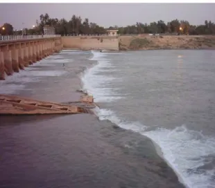
Figure 2 - Fishway at Ask- Hendijan Diversion Dam in Iran (Ahvaziyan et al., 2009)
Weir and pool type of fishway was designed and installed for the first time in Khuzestan at Ask- Hendijan diversion dam in Iran. This Weir and pool type of fishway is composed of eleven pools. Between every the two pools, there is a baffle as a overflow. The weir height is 75 cm
from the upper floor and 100 cm from the lower floor. Under the baffle, an oriffice were considered for the passing of fish (Ahvaziyan et al., 2009).
2. MATERIAL AND METHODS
In this study, flow is unsteady with two-dimensional turbulence form. Velocity and pressure are a function of time and space. To model of the velocity and pressure fluctuations is the integrated from the Navier Stokes equation at time. Integration of Navier Stokes equations at time is known Reynolds equations (Reynolds, 1984). Turbulence model equations
are two equation models k-ε (Standard) that
have be averaged in depth (Rastogi and Reddy,
1978).ε equation is as one of the main sources
of the limitations of accuracy of the standard
version of the k-ε model and the Reynolds
stress model. It is interesting that k-ε model includes a correction term that is dependent to
strain with c13 constant in the ε equation of
RNG model (Yakhot et al, 1992). WillCox
provided turbulence equations of k-ω
(standard) model (WillCox, 1988).
3. Problem definition and formulations 3.1. Reynolds equations
0 z w y v x u (1) z y x x P v f z uw y uv x uu t
u xx xy xz
c (2) z y x y P u f z vw y vv x uv t
v yx yy yz
c (3) g z y x z P z ww y vw x uw t
w zx zy zz
(4)
3.2. Turbulence model equation
Known two-equation model of k-ε (Standard) are presented for averaged form in depth as follows:
(Rastjy and Reddy, 1978).
hP hP h
x k h x x hk U t hk kv k k t j j
j
] )
[( (5)
ij ij t k
t P S S
k
c , 2 .
2
3 1 2 2 2 2 2 4 3 2 1 2 * 2 4 2 1 2 , 1 , , 1 , h g n w v u u c c c c e c h u c P c c k cP f f
f t f v f k k kv
(7)
(8) 31 . 1 , 0 . 1 , 92 . 1 , 44 . 1 , 09 .
0 1 2
c c k
c
kv
P and Pkv are production terms as result of non-uniform distribution velocity in depth that is
stronger near-bed. Pk is production term of turbulent kinetic energy averaged in depth as result of
velocity gradients in the plan. t is the vortex viscosity. Turbulence model is used for calculation of
lateral flow into one channel and is achieved much better results in comparison with t for fixed parameters of rotational flow (MCGurik and Rodi, 1978). cf is the bed friction coefficient. t is
Schmidt number that shows relationship between turbulence viscosity and turbulent diffusion coefficient according to the following equation:
t t
d
(9)
Amount oft is considered 0.5 (Keller and Rodi, 1988). Although values of t are 0.5 to 2 in
variable references (Gibson and launder, 1978). e* is coefficient that gives turbulence diffusion
coefficient in depth by following equation (Keller and Rodi, 1988).
f d e*hu
(10)
Direct measurement of color broadcasting in the fixed-width channels offers 0.15 fore*. Although
Keller and Rodi achieved better solutions for the velocity and stress within the composite channels
(Keller and Rodi, 1988). On the other hand Biglari and Sturm has been assumed e* equaled to 0.3 to
get the better answer within the composite channels (Biglari and Sturm, 1998). McGurik and Rodi
have considered
t
e* 1
equaled to 3.6 (McGurik and Rodi, 1978). In ε equation of RNG model
includes a correction term c1 that is constant strain-dependent (Yakhot et al, 1992). For k-ε (RNG),
we have: k hc hP P k hc x h x x h U t h v k t j j j 2 2 * 1 ] ) [( (11) 377 . 4 , ) . 2 ( , 42 . 1 , 012 . 0 , 39 . 1 , 68 . 1 , 1 ) 1 ( , 0845 . 0 0 2 1 1 1 3 0 1 * 1 k E E c c c c c ij ij k (12)
Only constant β is adjustable, high levels of turbulent data are obtained near-wall. All other constants
are calculated explicitly as part of the RNG process.
P
P
h
x
k
h
x
x
hk
U
t
hk
b k k t j j j
]
)
S k hc S hc P k hc x h x x h U t h k t j j j 2 2 1 1 ] )
[( (14)
85 . 0 Pr , ) ( 1 , 2 . 1 , 1 , 9 . 1 , 44 . 1 ), ( 2 1 , ~ , ~ ), 6 ( cos 3 1 , cos 6 , 04 . 4 , , , 1 , , Pr , , , , 2 , ], , 43 . 0 [ 2 1 3 1 0 * * 0 2 2 ' ' ' 2 1 t k j i i j ij ij ij ki jk ij s k ijk ij ij ij ij ij ij s t i t t i b t k i j j i k t ij ij p T P c c x u x u s s s s s s s s A A s s U KU A A c k c x T g P s P x u u u P k hc s s s k s s Max c (15)
WillCox, turbulence model k-ω (standard) equation to be provided as follows: (WillCox, 1988):
] ) [( * * j T j j i ij j j x k x k x U x k U t k (16) ] ) [( 2 j T j j i ij j j x x k x U k x U t (17) k k
t
* , * 2 1 , 100 9 , 40 3 , 9 5 ,
4. Numerical Model
The values of the physical properties of water are considered 998.2, 0.001003, 4182 and 0.6, respectively, for density, viscosity, heat capacity and thermal conductivity. Solutions of all governing equations are subject to assignment of variables correctly in the boundary nodes. In steady state problems required only boundary condition but in unsteady state problems is required the initial conditions for all nodes in the network. Common boundary conditions in hydraulic issues include (Soltani and Rahimi Asl, 2003): A- Inlet boundary condition: numerical models can fit the model by means of the various boundary conditions such as velocity, mass flow, etc. For example, in modeling of flow inside a closed or open channel can be used velocity inlet as input boundary condition. B- The outlet boundary condition is considered pressure outlet equals the atmospheric pressure. If the output is chosen at a far distance from geometric constraints, and no change in direction of flow then the flow state is developed full. Using this model is caused the
output surface is perpendicular to the flow and gradient is zero in the perpendicular direction on the output surface (Soltani and Rahimi Asl, 2003).
C - Wall boundary condition: the wall boundary condition is used to limit the area of between fluid and solid. The model is ready for simulation by Solutions set and defining the model.
The following steps show the simulation process (Versteeg and Malalasekera, 2007): selection methods of discretization equation: In this paper first order upstream difference method is used for discretization of momentum,
k, ε and ω equations and the standard method is
used to find the pressure. Selection methods of the relation velocity - Pressure: this step is only be studied segregated. In this paper is used from SIMPLE method for velocity - pressure coupling. Determine the discount factors: the discount factor values are used for control of calculated variables in the each iteration. In this paper, the default values 0.3, 1, 0.7, 0.8, 0.8
and 1 is used respectively for the pressure,
viscosity. In this paper, the initial values of the relative pressure is considered zero And the initial values of velocity components close to the average values presented in the input stream. By completing the steps in the numerical model, we can start the introduced process of problem by defining of repeat process. The frequency of reporting of results can be introduced before computing the numerical model. During solution process can be seen convergence of solution by the control of residues, integral of surface, statistics and values of the force. After finishing solution the computation of the unknown quantities and the results can be calculated at any point of the field and can be displayed by vector in the form, contour and profile views (Versteeg and Malalasekera, 2007). In this paper for solution
of flow is usually introduced initial number repeat 1000 with report of every step of the calculation. Conditions for convergence of the unknown parameters were satisfied after 300 to 350 iterations.
5. Meshing model
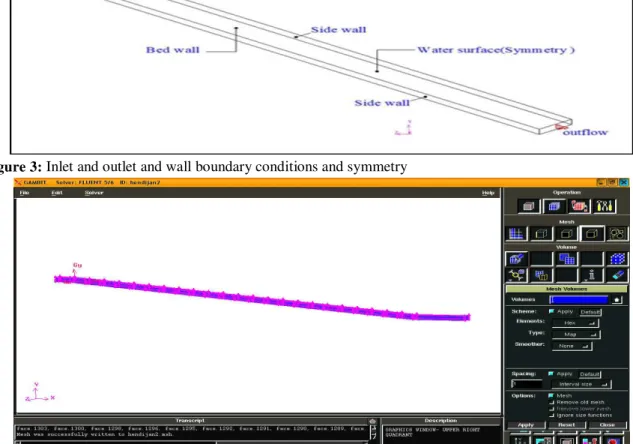
Gambit software version 2.3.16 is used to generate the channel geometry and meshing. Model of the network is used Quad element and the types of Map and Pave for pages and Hex elements and types of Map of Cooper for volumes. Inlet and outlet and wall boundary conditions and symmetry were introduced in the software as figure 3. Water inlet velocity is considered 1.9 meters per second in non-submerged state and 1.6 meters per second in submerged state.
Figure 3: Inlet and outlet and wall boundary conditions and symmetry
Figure 4: Meshing of Ask - Hendijan fishway in submerged state and with orifice below of it.
6.
CONCLUSIONSIn this paper, the governing equations in
three dimensional shallow water of fishway
were
solved
by
using
appropriate
turbulence model. The flow pattern and
turbulence
is
calculated.
Hydraulic
should be more fish. Critical velocity rate is
considered 2.5 meters per second for adult
Salmon. The results of the numerical model
were compared to results by Micromolineh
in the Karkheh Hamidieh fishway. Results
show at figures 5 to 7.
Figure 5: displays velocity lines in the pools of fishway at submerged mode with k-ε (RNG) turbulence model
Figure 6:displays velocity lines in x- direction in the pools of fishway at submerged mode with k-ε (Standard) turbulence model.
Figure 7:displays x velocity lines in the pools of fishway at submerged mode with k- standard turbulence model.
7. RESULTS
Pool and weir is a type of fishways that make possible migration of fish to upstream of the dam. Velocity, water depth and turbulence are
the effective parameters in swimming of fish. In this paper, the three-dimensional equations governing shallow water in weir and orifice fishway are solved with suitable models of Flow direction between pools in fishway
Flow direction between pools in fishway
turbulence that flow pattern and turbulence can be calculated. Figure 5 shows velocity lines in the pools of fishway at submerged mode with constant velocity about 0.4 to 0.6 meters per second. Figure 6 shows velocity lines in the pools of fishway at submerged mode with Constant velocity about 0.4 to 0.6 meters per second. The amount of quick burst of speed is considered 2.5 meters per second for adult fishes. Figure 7 shows velocity lines in the pools of fishway at submerged mode with Explosive velocity about 2.2 meters per.
Two-equation turbulence models show the
importance of the turbulence model as k- standard and RNG in numerical simulation as an effective tool for design of fishway.
8. REFERENCES
1. Ahvaziyan, H., Salj Mahmoudi, H. and
Bagheri, B., (2009), "Correction of application of fishway structure in Ask- Hendijan diversion dam, 8th conference of River engineering, Ahvaz, Iran.
2. Beach, M. A., (1984), "Fish Pass Design,"
Fish. Res. Teach. Rep. No. 78, Min. Agric. Fish. Food, Lowestoft, England. 46pp.
3. Bell, M. C., (1984), "Fisheries Handbook
of Engineering Requirements and
Biological Criteria," U.S. Army Crops of Engineers, North Pac. Div., Portland, OR. 290 PP.
4. Carrica, P. M., Turan C. and Weber, L.,
(2005), ”Computation of the free surface
flow in fish passage,” Mwcanica
computational VOL.XXIV.
5. Cea, l., Pena, l. and Puteras, j., (2007),
”Application of Several Depth Averaged turbulence models to simulate flow in vertical slot fishways,” J. Hydraulic Eng, ASCE, February 2007, P 160.
6. Chen, Q., Dai, G. and Liu, H., (2001),
“Volume of fluid model for turbulence numerical simulation of stepped spillway overflow,” J. Hydraulic Engineering. ASCE.
7. Clay, C. H., (1995), "Design of fishways and other fish facilities," Dept. of Fisheries
of
Canada, Ottawa,301pp.
8. Katopodis, C., (1981), “Consideration in
the design of fishways for freshwater species,”Proc., 5th Can.
9. McGrath, C. J. (1995). A report on a studu
Tour of fisheries Developments in Sweden, Fish.Br., Dep. Lands, Dublin. 27 pp.
10. Orsborn, J. F., (1985), "Development of
New Concepts in Fish-Ladder Design," Bonneville Power Admin. Proj. No. 14-82. Pts. 1-4.
11. Pavlov, D. S., (1989), "Structures
Assisting the Migrations of Non – Salmonid Fish," U.S.S.R., FAO.
12. Rastogi, A. K., and Rodi, W., (1978),
"Prediction of Heat and Mass Transfer in Open Channels," Journal of Hydraulics Division, ASCE, 104(3), 397- 420.
13. Reynolds, O., (1984), "On the Dynamical
Theory of Incompressible Viscous Fluids and the Determination of the Criterion," Phil. Trans. Roy. Soc. London, 1986, 123-161.
14. Sasanabe, S., (1990), "Fishway of
headworks in japan," Proc. Int. Symp. On fishways 90, Gifu, Japan.
15. Savage, B. M. and Johnson, M .C., (2001),
“Flow over ogee spillway: physical and numerical model casestudy,” J. Hydraulic Engineering. ASCE.
16. Soltani, M. V. and Rahimi Asl,R., 2003.
Computational Fluid Dynamics by Fluent Software, Tehran, Tarrah issues.
17. Versteeg, H. K. and Malalasekera, W.
1995. An Introduction to Computational
Fluid Dynamics.
18. Washburn, M. and Assoc, G., (1985),
"Upstream Fish Passage," Can. Elect. Assoc. Res. Rep. No. 157 G.
19. Wilcox, D. C., (1988)., "Re-assessment of
the scale-determining equation for
advanced turbulence models," AIAA Journal, vol. 26, pp. 1414- 1421.
20. Yakhot, V., Orszag, S.A., Thangam, S.,
Gatski, T. B. and speziale, C. G., (1992), " Development of turbulence models for shear flows by a double expansion technique," Physics of Fluids A, Vol. 4, No.7, pp1510-1520. 340 pp.
21. Zarnecki, S., (1960), Recent changes in the