American Journal of Engineering Research (AJER)
e-ISSN: 2320-0847 p-ISSN : 2320-0936
Volume-5, Issue-11, pp-257-261
www.ajer.org
Research Paper Open Access
w w w . a j e r . o r g
Page 257
Optimal Control of Dc Motor Using Performance Index of
Energy
Arnisa Myrtellari
1, Petrika Marango
2, Margarita Gjonaj
3123
Polytechnic University of Tirana, Faculty of Electrical Engineering, Department of Automation,
Tiranë,Albania
ABSTRACT:
DC motors are widely used in the mechanisms that require control of speed. PID controller are widely used for speed control. But they aren’t suitable for high performance cases, because of the low robustness of PID controller. Many researchers have been studying various new control techniques in order to improve the system performance. In dynamic regimes, the conversion efficiency is diminished to about half while during the stationary regime the efficiency is increased. The main drawback of these drives is the obtained diminished electrical energy during the transient regimes, i.e. starting, braking or reversing. The paper objective is to validate a new control, optimal type, which minimizes the consumption of the necessary energy to perform a given state trajectory. Two problems are presented in this paper: the problem formulation and the energy saving control solution, the numerical simulation. The numerical results confirm the performances of the proposed control method.Keywords:
optimal control, energy, DC MotorI.
INTRODUCTION
The DC motors are comprehensively used in various industrial applications such as electrical equipment, computer peripherals, robotic manipulators, actuators, steel rolling mills, electrical vehicles, and home appliances. Its applications spread from low horse power to the multi-mega watt due to its wide power, torque, speed ranges, high efficiency, fast response, and simple and continuous control characteristics. The speed of DC motor can be changed by controlling the armature and field voltages. The dynamic regimes of DC motor, such as starting and stopping, occur very often during normal work. These frequent dynamic regimes diminish considerably the conversion’s efficiency, which is higher in the stationary state. The conventional control using P and/or PI controllers or other advanced techniques has as objectives a good dynamic behaviour and realization of the given trajectory with a minimum error. There are theoretical results validated by numerical simulation concerning the energetic optimal control of DC and AC electric drive systems[7], which take into consideration the minimization of the consumption energy during the transient periods, e.g. starting, stopping and reversing. The numerical results indicate the certain possibilities to decrease the consumption energy [3,5].
w w w . a j e r . o r g
Page 258
II.
PROBLEM
FORMULATION
DC motor is a power actuator which transforms electrical energy in to mechanical energy. DC motor is widely used in many industrial applications where wide range of speed –torque characteristics required. In this paper, the separated excited DC motor model is chosen according to his good electrical and mechanical performances more than the other DC motor models. A DC motor, controlled by armature voltage, constant field is an invariantcontrollable dynamic system described by the differential equations.
t u L t i J R t L k dt t di t m J t i J k t J b dt t d s 1 ) ( ) ( ) ( 1 ) ( ) ( ) ( (1)
In the space state the differential equations (1) get the form
Ax
Bu
( )x t t t Gw t
(2)
where the state is given by
Tt i t t
x( )
(3)
The control problem consists in finding of an admissible control, armature voltageu(t), which transfers the system (2) from the initial state
Tx(0) 0 0 (4)
to a desired state
Ti t
x1( ) 1 1 (5)
in the fixed time t1, ɷ1 being the desired final speed, with minimization of the consumption energy. In order to minimize the consumption energy, the index performance criteria of energy in the form
t
S
t
t
t
t
t
dtJ f t T
0 T T 1 1 11 x Qx u Ru
2 1 x -x x -x 2 1 (6)
Is associated to system (2), where weighting matrices S and Q are 2×2 positive semidefined matrices and R is a 1×1 positive defined matrix. The optimal control problem is: with free end point, fixed time and unconstrained. The restrictions of the magnitude for the control and state could be solved by the adequate choice of the weighting matrices. The direct minimization of drawn energy can be achieved by introducing input power
) ( ) ( ) ( ) ( 2
1 u t i t u t x t
P (7)
in index performance criteria (6). There are more power losses which are determinated by the angular speed: eddy current losses
) ( 2
t k
pF F (8)
hysteresis power losses ) (t k
pH H (9)
viscous power losses
) ( 2
t b
pV (10)
also the output mechanic power has the form
(11) wherekF , kH , b are constant coefficients.
III.
METHODOLOGY
The solution of the problem exists and is unique if the system (1) is controllable and completely observable and the weighting matrices carry out the above conditions [2,5].By using the variational method, the Hamiltonian ofthe optimal control problem is
( ) ( ) ( ) ( ) ( ) ( )
2 1 ) ), ( ), ( ( ) ( ) ), ( ), ( ( ) , , ,(x u t g x t u t t t f x t u t t x t Qx t u t Ru t t x t
H T T T T (12)
λ(t) being costate vector.
Therefore the following canonic system is obtained )
(t k
w w w . a j e r . o r g
Page 259
) ( 0 ) ( ) ( ) ( ) ( 1 t w G t t x A Q B BR A t t x T T (13)The well known boundary conditions result from initial state x(0)=x0 transversalitycondition
1 1
1) ( )
(t S x t x
(14)
The solution of the problem is given by
) ( ) ( 1 * t y B R t
u T
(15)
where x(t) and y(t), the cost vector being the solution of the canonical Euler-Lagrange system. The optimal control law at any moment ‘t’ is
) ( ) ( ) ( ) ( ) ( )
( 1 1 1 1 1 1 1 2 1
* t w t t K B R x t t K B R t x t t P B R t
u T T T (16)
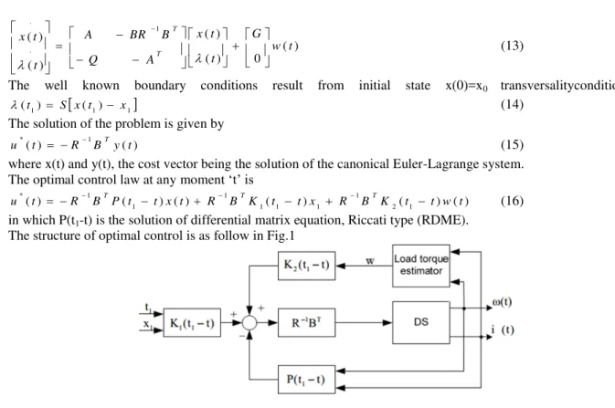
in which P(t1-t) is the solution of differential matrix equation, Riccati type (RDME). The structure of optimal control is as follow in Fig.1
Fig.1 Structure of optimal control law
The optimal control solution (16) has three components: the state feedback, the reference to achieve the desiredfinal state x1, the compensating feedforward of the perturbation w(t ) effect, Fig.1. The solution is a
non-recursive one and can be computed for any value of t, from initial time t=0 to the final time t1.
IV.
NUMERICAL
RESULTS
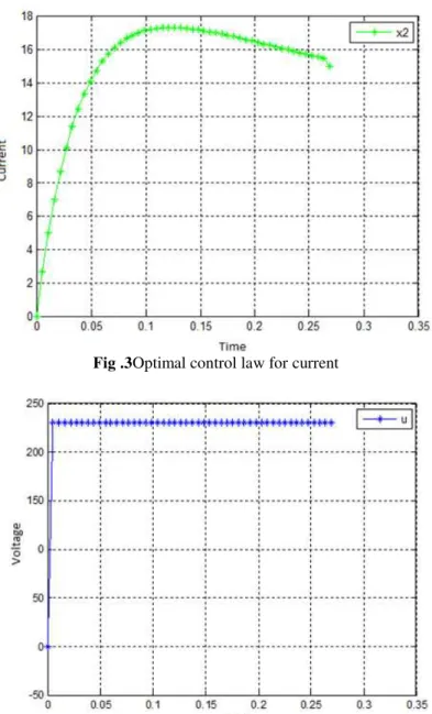
The system (1) was numerically simulated using a discretized model and Matlab/Simulink software. The system parameters are:1.5 kW, 1200rpm, 15A.The simulation results are presented in Fig.2, Fig.3 and Fig.4 and concretely we have optimal control for speed, current and voltage of DC motorby accepting that:
x1(t)=ɷ(t) and x2(t)=i(t).
w w w . a j e r . o r g
Page 260
Fig .3Optimal control law for current
Fig .4Optimal control law for voltage
V.
CONCLUSION
In order to enhance the conversion efficiency of the DC drive systems a new optimal control law, which minimizes the drawn energy, was developed. The solution properties have been tested via simulation, using MATLAB-SIMULINK. With respect to conventional control, the optimal proposed control for a DC drive system minimizes the drawn energy to perform a given trajectory. The reduction in the drawn energy leads to the decreasing of the energy expenditure.The main features of the proposed optimal control law are: the solution of control is an analytical one, high dynamic performances, without overshoots and good robustness to the load variation decreasing the drawn energy with about 6% to 10% for a dynamic regime as starting, stopping and reversing; the optimal control is linear and unconstrained being applicable only for linear drive systems; voltage, current and speed limits can be maintained within strict limits by adequate choice of the weighting matrices; the optimal control can be mixed with conventional control in the aim to assure the works, dynamic and steady state regimes.
REFERENCES
[1] T. Egami, H. Morita and T. Tsuchiya, Efficiency Optimized Model Reference Adaptive Control System for a DC Motor, IEEE
Transactions on Industrial Electronics, 37(1), 1990, 28-33.
[2] A.Myrtellari, P. Marango, M.Gjonaj, Analysis and Performance of Linear Quadratic Regulator and PSO algorithm in optimal
control of DC motor, International Journal of Latest Research in Engineering and Technology,2(4), 2016, 88-93
[3] M. Athans, P. L. Falb, Optimal Control: An Introductionto the Theory and Its Applications, New York: Dover Publications, 2007
w w w . a j e r . o r g
Page 261
[5] Naidu. D. S, Optimal Control System, CRC Press LLC,2003
[6] M. Athans, P. L. Falb, Optimal Control: An Introductionto the Theory and Its Applications, (New York: Dover Publications,
(2007),250-300
[7] Wai- Chuen Gun, Robust and optimal control of AC machines, doctoral diss, Hong Kong University of Science and Technology,
2001
[8] W.J. Book, J. Li, L. Xu, Z, Zhang, A new efficiency optimization method on vector control of induction motor,Proc. IEEE Conf.