J. Serb. Chem. Soc. 74 (7) 773–779 (2009) UDC 66.088:546.26–162:531.728:53.086
JSCS–3875 Original scientific paper
doi: 10.2298/JSC0907773R
Laser reflection spot as a pattern in a diamond
coating – a microscopic study
GORDANA S. RISTIĆ1*#, MILAN S. TRTICA1#, ŽARKO D. BOGDANOV1,
ZLATKO LJ. RAKOČEVIĆ1 and ŠĆEPAN S. MILJANIĆ1,2
1VINČA Institute of Nuclear Sciences, P.O. Box 522, 11001 Belgrade, and 2Faculty of Physical Chemistry, University of Belgrade, P.O. Box 137, 11001 Belgrade, Serbia
(Received 3 July 2008, revised 13 March 2009)
Abstract: Diamond coatings were deposited by the synchronous and coupled action of a hot filament CVD method and a pulsed CO2 laser in spectro-ab-sorbing and spectro-non-abspectro-ab-sorbing diamond precursor atmospheres. The ob-tained coatings were structured/patterned, i.e., they were comprised of unco-vered, bare locations. An extra effect observed only in the spectro-active dia-mond precursor atmosphere was the creation of another laser spot in the coat-ing – a reflection spot. In order to establish the practical usability of the latter one, extensive microscopic investigations were performed with consideration of the morphology changes in the spot of the direct laser beam. Normal inci-dence SEM images of this spot showed a smooth surface, without any pulse radiation damage. AFM imaging revealed the actual surface condition and gave precise data on the surface characteristics.
Keywords: diamond coating; hot filament CVD; CO2 laser; radiation reflection; SEM; AFM.
INTRODUCTION
A wealth of high-valuable technological properties of diamond has become fully available in thin film form by chemical vapour deposition (CVD). The hot filament chemical vapour deposition method (hfCVD) is a simple and inexpen-sive approach for obtaining good quality diamond films. The joint, synchronous action of a laser – the synergy – in the course of diamond coating deposition, enables a patterned coating to be obtained in a single-step procedure without any previous or subsequent processing. The main purpose of achieving the hot fila-ment CVD-pulse CO2 laser synergy in the synthesis of a diamond coating is to
use the hot filament for the production of atomic hydrogen in sufficient quantities and the pulse CO2 laser as a pattern-writing agent.
* Corresponding author. E-mail: [email protected]
The synergy of the hot filament CVD method with a number of lasers ope-rating in a broad spectral region was realised in order to obtain diamond coatings. Different lasers were used: excimer lasers ArF (193 nm)1,2 and XeCl (308 nm);1,3
an Ar-ion laser (514.5 nm);4 a pulsed, frequency-doubled Nd:YAG laser (532
nm);5,6 a continuous wave (cw) Nd:YAG laser (1064 nm);7 a cw/pulsed CO2
laser (10.6 μm)8 and a pulsed CO
2 laser.9 In all these cited works, except for two,
the spectro-non-absorbing diamond precursor, CH4 (1–3 %) in H2 was used.
A spectro-absorbing diamond precursor atmosphere in the synergy laser–con-ventional CVD method takes advantage of another specific, important charac-teristic of laser radiation – monochromacity (in addition to high-directionality and high-intensity), which justifies the use of rather expensive/sophisticated ins-trument. In a spectro-absorbing diamond precursor atmosphere, the synergy of the hot filament CVD method with either an ultraviolet excimer laser1 or an infrared-pulsed CO2 laser9 enables specific coating patterning – by deposition
suppression, i.e., impoverishment in irradiated locations. The obtaining of another laser spot in the coating, the reflection spot, indicated a possibility of exploiting the beneficial and avoiding the detrimental effects of pulse laser radiation. An SEM comparison of the spots created by the direct laser beam and by the reflec-ted laser beam showed the absence of any substrate surface damage in the latter case. Microscopic investigations of the reflection spot down to the nano-scale were additionally undertaken in order to ascertain the substrate surface quality required for applications in diamond coating technologies.
EXPERIMENTAL
A reaction cell with a hot filament and a TEA pulsed CO2 laser were set opposite to each
other on the same optical axis, in order to accomplish their synergy. The reaction cell with the hot filament was coupled to a vacuum apparatus equipped with a pump, a pressure gauge and a gas flowmeter. The Ta filament (0.5 mm diameter) was supplied with electrical current from the a.c. mains through variable transformers. Molybdenum was chosen as the target/substrate in all synergy experiments, based on a study of different substrate materials for diamond CVD.10 The Mo substrate (20 mm×10 mm×0.5 mm), mirror-polished by a standard
metallo-graphic procedure, unseeded, was mounted at a distance about 5 mm from the filament. The working parameters were as follows: substrate temperature ≈ 900 °C, filament temperature 2100–2200 °C, total working pressure 30 mbar, gas flow rate 50 cm3 min-1, experiment
dura-tion tdep = tirr = 2.5 h. Gaseous mixtures, C2H4 (0.5 %) in H2, C2H4 (7.5 %) in H2 and CH4 (1 %) in H2, were prepared before the experiments.
Radiation of the pulsed TEA CO2 laser11 was focused by a ZnSe lens (f = 25 cm) onto
the Mo target/substrate mounted in the reaction cell at a distance from the filament of ≈ 1–2 mm. The laser working characteristics were as follows: pulse power (at a spike) 0.5 MW; pulse duration 120 ns (initial spike), ≈ 2 μs (pulse “tail”); repetition rate ≈ 3 Hz; output wa-velength 10.6 μm; multimode working regime; spot size at the focus ≈ 1 mm2; beam incidence
angle to the surface 90°.
substrate surface in the reflection spot was imaged by a powerful, high-resolution AFM ins-trument, Digital Nanoscope (Nanotec Electronica, Spain), working with WSxM software.12
RESULTS AND DISCUSSION
The diamond coating was deposited by the simultaneous action of the hot filament and the pulsed CO2 laser from the spectro-absorbing diamond precursor
atmosphere, C2H4 (0.5 %) in H2. The obtained coating contained two laser spots
situated in regions of reduced thickness. The first spot was created at the focus of the direct laser beam. Deposition impoverishment in the spot surrounding and moderation of the photothermal effect in the spot centre were explained by ab-sorption of the laser beam in ethene.9
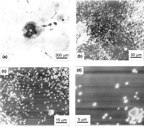
The second spot, made synchronously with the first one, is presented in the SEM micrographs shown in Figs. 1a–1d. The whole spot can be seen in Fig. 1a. A “patch deposit” gathered in the middle point of the spot is shown in Fig. 1b. The diffuse spot border and the gradual crystallites rarefaction indicate the influence of the spectro-active agent during the deposition, Fig. 1c. A detail from
Fig. 1. Diamond coating of synergy obtained from C2H4 (0.5 %) in H2:
the spot is shown in Fig. 1d. This spot resulted from specular reflection at the mirror-finished Mo substrate and backward reflection at the laser output coupler. It is well known that the reflectivity of metals increases with increasing incident radiation wavelength, and that for a CO2 laser, the radiation reflectivity
ap-proaches unity (for molybdenum R = 0.98513). After specular reflection at the Mo substrate, the radiation reverted through the lens, become defocused after the focal point, i.e., diverged, and reached the Ge output coupler* placed at an over-focus. At the coupler, the radiation is partly cast back, the straying rays travelled the same optical way, and then converged to create the reflection spot, and a cycle recurred until being extinguished by the absorbing medium. The speckle deposit in the spot centre, Figs. 1a and 1b, means that the laser radiation did not act at this point, which might indicate a possibility of a self-absorption effect of the laser radiation. On the other hand, deposition impoverishment in the spot stands just for action of the laser.1,9 At the same time, the uncovered substrate
surface in the spot without cracks produced by the pulse laser radiation, Figs. 1c and 1d, seemed as an acceptable/promising outcome of the laser action – a dia-mond coating pattern.
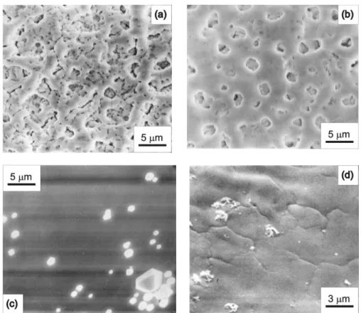
In order to compare laser modifications of the substrate surface effected in different working atmospheres, SEM micrographs (of the same/higher magnifi-cation) of the examined spot centres are given in Figs. 2a–2d. The modified substrate surface from the synergy experiment in the spectro-inactive diamond precursor atmosphere, CH4 (1 %) in H2 is presented in Fig. 2a. Figure 2b
origin-nates from the spot made at the direct laser beam focus, and Fig. 2c stems from the reflection spot; both spots were created in the spectro-absorbing diamond pre-cursor atmosphere, C2H4 (0.5 %) in H2. The spot made at the laser beam focus in
the highly concentrated diamond precursor atmosphere, C2H4 (7.5 %) in H2 is
shown in Fig. 2d. The effects of the laser radiation in the resulting coatings differ considerably: in the methane atmosphere, a laser radiation fluence of 15 J cm–2
produced the shown morphology pattern on the surface after removal of the dia-mond coating, Fig. 2a. In C2H4 (0.5 %) in H2, the “palliated” surface
morpho-logy in the spot centre created at the direct laser beam focus, Fig. 2b, reveals damping of the laser radiation in the optically dense medium (simultaneously, the coating impoverishment in the spot surroundings confirms draining of the dia-mond precursor into a photolytic reaction channel), as has already been explain-ed.9 In the reflection spot, Fig. 2c, no cracks in the uncovered surface are visible; they might have vanished by radiation moving to and fro in the spectro-absorbing diamond precursor/medium. Only faint marks/traces of surface cracking seen in the spot centre created at the direct laser beam focus in C2H4 (7.5 %) in H2, Fig.
2d, confirm the already noticed damping effect of the laser radiation in the
spectro-absorbing atmosphere.* These micrographs indicated the convenience of using the radiation reflection effect in the spectro-active diamond precursor in the studied synergy: diamond coating deposition with simultaneous patterning, without underlying surface damage to the substrate.
Fig. 2. Laser surface modifications/spots effected in different atmospheres during hfCVD-pul-sed CO2 laser synergy: a) spot created by the direct laser beam in CH4 (1 %) in H2; b) spot
created by the direct laser beam in C2H4 (0.5 %) in H2; c) spot created by the reflected laser beam in C2H4 (0.5 %) in H2; d) spot created by the direct laser beam in C2H4 (7.5 %) in H2.
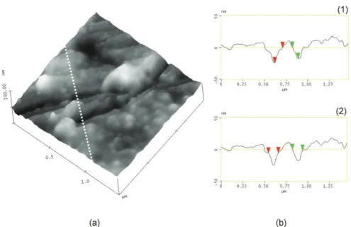
Microscopic examination reaching even higher magnifications was under-taken in order to corroborate these findings. The morphology of the uncovered surface in the reflection spot is given by the AFM 3D-image (1.5 μm×1.5 μm) in
Fig. 3a. Profile analysis of the examined surface segment, performed along the white, dashed line, is presented in Fig. 3b. The depth of the observed cracks (ver-tical distance between cursors) was ascertained in Fig. 3b, Graph (1), and equals
* Effect of the radiation reflection in the course of the hfCVD-pulsed CO2 laser synergy was not observed in the spectro-unabsorbing precursor, CH4 (1 %) in H2, due to the formation of a
18 and 24 nm. The width of the observed cracks (horizontal distance between cursors), seen in Fig. 3b, Graph (2), amounts to 120 and 160 nm. The roughness of the examined surface segment is 7.5 nm (all numerical values are rounded). The presented evidence indicates that the pulsed laser radiation produced nano-scale surface damage in the reflection spot created in the micrometer-thick dia-mond coating. Consequently, applications which are unaffected by nanometric defects of the substrate surface are suitable for this method of coating patterning.
Fig. 3. Uncovered substrate surface in the reflection spot taken by AFM: a) 3D-surface view of the morphology (the white, dashed line indicates the location of the section analysis); b) profile of the section analysed, giving the depth (1) and width (2) of the registered flaws.
Hence, the main idea which induced these investigations, the prospective employment of reflected laser radiation for diamond coating patterning, gave se-veral results: a proper evaluation of effects and concluding with possible appli-cations.
CONCLUSIONS
– Irradiation of a mirror-polished substrate surface in a spectro-absorbing diamond precursor atmosphere during hot filament-pulsed CO2 laser synergy
– This procedure of coating patterning is recommended for applications in-sensitive to nanoscale surface flaws.
Acknowledgements.This work was financially supported by the Ministry of Science and Technological Development of the Republic of Serbia, under projects 142065 and 142067.
–
. 1, . 1, . 1, . 1 . 1,2
1Institut za nuklearne nauke VIN^A, p.pr. 522, 11001 Beograd i 2Fakultet za fizi~ku hemiju,
Univerzitet u Beogradu, p.pr. 137, 11001 Beograd
CO2
. / , .
-, . ,
-, –
. ђ
,
-.
-.
.
( 3. 2008, 13. 2009)
REFERENCES
1. F. G. Celii, H. H. Nelson, P. E. Pehrsonn, J. Mater. Res.5 (1990) 2337 2. Y. Goto, T. Yagi, H. Nagai, Mat. Res. Soc. Proc.129 (1989) 213 3. H. Chen, N. Mafei, R. H. Prince, J. Appl. Phys.76 (1994) 8113
4. M. Lindstam, M. Boman, J. O. Carlsson, Appl. Surf. Sci.109/110 (1997) 462 5. Q. Wang, R. Schliesing, H. Zacharias, V. Buck, Appl. Surf. Sci.138/139 (1999) 429 6. G. F. Zhang, V. Buck, Appl. Surf. Sci.180 (2001) 255
7. Z. Toth, A. Mechler, P. Heszler, Appl. Surf. Sci.168 (2000) 5
8. J. Gaze, T. Obata, N. Oyanagi, H. Izawa, W. L. Zhou, M. Kusunoki, Y. Ikuhara, Nucl. Instr. Meth. Phys. Res. B121 (1997) 427
9. G. S. Ristić, M. S. Trtica, Ž. D. Bogdanov, N. Ž. Romčević, Š. S. Miljanić, Appl. Surf. Sci.253 (2007) 5233
10. G. S. Ristić, Ž. D. Bogdanov, S. Zec, N. Romčević, Z. Dohčević-Mitrović, Š. S. Miljanić, Mater. Chem. Phys.80 (2003) 529
11. M. S. Trtica, B. M. Gaković, B. B. Radak, Š. S. Miljanić, in Proceedings of SPIE, Vol. 4747: International Conference on Atomic and Molecular Pulsed Lasers IV, (2002), Tomsk, Russia, (2001), p. 44
12. I. Horcas, R. Fernandez, J. M. Gomez-Rodrigez, J. Colchero, J. Gomez-Herrero, A. M. Baro, Rev. Sci. Instruments78 (2007) 013705