Comparative Study of 1-D Chaotic Generators for
Digital Data Encryption
Abir Awad, Safwan El Assad,
WANG Qianxue, C
ă
lin Vl
ă
deanu, Bassem Bakhache
Abstract—The security of transmitted digital information through a channel, against passive or active attacks, becomes more and more important. The use of a 1-D chaotic signal to mask useful information and to make it unrecognizable by an eavesdropper is a field of research in full expansion. In order to obtain such high-level security; chaotic generators used to encrypt digital data, must have desirable dynamical statistical properties such as: noise-like autocorrelation, cross-correlation, uniformity, attractors, etc. In this paper; first, we design, improve and simulate using Matlab some 1-D chaotic generators: Logistic map, PWLCM (PieceWise Linear Chaotic Map) map, Perturbed PWLCM map, Frey map, perturbed Frey map, (n, t)-tailed shifts map and perturbed one. Second, we show the importance of perturbed chaotic orbit with a comparative study of the dynamical statistical properties obtained under simulation and Nist
tests.
Index Terms—Chaotic sequences generators, encryption, dynamical degradation, perturbed chaotic orbit, security.
I. INTRODUCTION
Recently, chaos has been widely studied in secure communications [1, 2], and the idea of using digital chaotic systems to construct cryptosystems has been extensively studied since 1990s, and attracts more and more attention in the last years [3, 4]. Chaotic output signal of one dimensional chaotic generator is used for both confusion and diffusion operations in a cryptosystem. In order to be used in all applications, chaotic sequences must seem absolutely random. Therefore, we need a digital chaotic generator with good cryptographic properties, such as: balance on {0, 1}; long cycle-length;
high linear complexity; δ-like autocorrelation; cross-
Manuscript received June 30, 2008. This work is made within the framework of the research project “ACSCOM”, “Apport du Chaos dans la Sécurité des systèmes Communicants Optiques et Mobiles” supported by ANRT.
Abir Awad, Safwan El Assad and WANG Qianxue are with IREENA, polytechnique school of Nantes university. Christian pauc street BP 50609 Nantes Cedex 3, France (phone: + 40683074; fax: + 33-2-40683233; e-mail: [email protected], [email protected]).
Călin Vlădeanu is with Telecommunications Department, “Politehnica”
University of Bucharest 1-3 Iuliu Maniu Bvd., Bucharest, Romania. Bassem Bakhache is with engineering faculty, Lebanese university, Kobbé , Tripoli, Lebanon.
correlation near to zero; desired attractor (with free space).
In [3,5], the authors show that logistic map don’t verify the randomness properties. In [2,6], we show some good chaotic maps for DS-CDMA communication systems. In [4], we prove the efficacy of perturbed PWLCM with our encryption algorithm. Also in [7], an analysis of another parametric PWL chaotic map and its utilization for secure transmission system based on the CSK principle is provided.
In this paper, we study and improve some existing techniques used to generate chaotic signals with desired statistical properties.
An experimental comparison of dynamical systems properties for the generators under test is made using Matlab. Such study will permit us choosing the best chaotic generator to be used in a cryptographic system.
Digital chaotic systems working in a N
2 -dimensional
finite space, introduce deterministic quantization (round-off, truncated or ceiled) errors in discrete iterations, and then pseudo orbits become different from theoretical ones even after a short number of iterations. Consequently, dynamical degradations of digital chaotic signal occur. Furthermore, all pseudo orbits are possibly periodic and
their cycle lengths are shorter than N
2 . To avoid the
dynamical degradation, two techniques can be used: cascading multiple chaotic systems and pseudo randomly perturbing the chaotic system. The second solution is better. We will explain and use it. Then, we will do a comparative analysis of these methods in order to conclude by choosing the best one. This paper is organized as follows. The second paragraph is presenting some chaotic maps. The third part describes the proposed perturbation technique. The fourth part presents some simulation results. Finally, some conclusions are drawn.
II. PRESENTATION OF SOME CHAOTIC 1D
GENERATORS
A.Logistic map
one-dimensional map, is a rule for getting a number from a number [3, 5, 8].
x n( )= F x n[ ( −1)]= p× x n( −1)× −(1 x n( −1)) (1)
The secret key always includes the initial condition x(0)
and the control parameter p within the interval (0; 4];
( )
x n is in [0; 1]. The Logistic map has been well-studied
in the past, and it had been demonstrated that the control
parameter p should be greater than the accumulation point
3.569945672 in order to maintain the highly chaotic state.
B. PWLCM map
Due to the poor balance property of Logistic map, some implementations use the following Zhou's map with better balance property [8].
A piecewise linear chaotic map (PWLCM) is a map composed of multiple linear segments (limited breaking points are allowed).
( )
(
)
(
)
(
)
(
)
(
)
(
)
(
)
[ 1 ]
1
1 0 1
1
1 1 0.5
0.5
[1 1 ] 0.5 1 1
x n F x n
x n if x n p
p
x n p if p x n
p
F x n if x n
= −
− × ≤ − <
= − − × − ≤ − <
− − ≤ − <
(2)
where the positive control parameter pє (0, 0.5) and x(i) є
(0, 1).
C. (n, t) – tailed shifts map
A well known family of PWAM (piece Wise Affine Markov) that generate chaotic sequences are the (n,t)-tailed shifts map [6, 9].
− − − < ≤ + − = − ) / (mod ) / ) (mod( )) ( ( 0 ) ) (( ) ( n t n t n n t n x t n t n x if n t x t n x
M (3)
It is known that these maps are exact and have a uniform invariant probability density function [9].
D. Frey map
An approach to generate chaos for secure
communications has been demonstrated by Frey. The
codec uses a non linear filter with finite precision (N bits)
in conjunction with its inverse filter [1, 2]. The non linear function used is the left circulate function suited to hardware implementation.
In figure 1, we present the structure of Frey generator. The
generator scheme consists in a non linear function FNL(x)
with a delayed feedback loop. The general equation is defined by the following relation:
1
( ) { ( ) m[ ( ) ( )]}
u NL u i u i
i
e n F k n G e n D s n
=
= + ∑ × − + (4)
where 1 2 ( ) mod(2 ) N NL N
x if x
F x x otherwise − < =
(5)
The index u in equation (4) denotes an unsigned number.
Also, all additions are modulo 2N. These operators are
assumed to be generally nonlinear operations.
The coder uses the following particular case of the system driven by equation (4):
2
=
m , G1=1, G2=2, D1=1, D2=2, as shown in figure 2.
All operations inside the loop work in the unsigned
number representation modulo 2N. The delivered chaotic
signal eu(n) is composed by 2N quantized levels
including the interval between [0, 2N−1], and having the
duration of Tch seconds for each chip:
{
}
{
}
( ) mod ( ) mod ( 1) ( 2)
u u u u
e n = k n + e n− +lcirc e n − (6)
where
{
}
( 2) mod 2 ( 2) ( )
u u u
lcirc e n − = e n− +s n (7)
and
1
0 ( 2) 2
1
N u
u
if e n s n
otherw ise
−
− <
=
(8)
The carry bit function s nu[ ] plays the role of a noise
source that is correlated in a nonlinear way to the
responsee nu( ). The input signal k nu( ) plays in our
application the role of an additional key, which does not allow an unauthorized eavesdropper to recover the
generated signal. However, k nu( ) can be used as
information signal to encrypt.
Using equations (6) and (7) we can rewrite equation (6) as following:
( ) mod ( ) ( 1) 2 ( 2) ( )
u u u u u
e n = k n +e n− + e n− +s n (9)
where the system states are given by:
1( ) u( 1)
x n =e n− and x n2( )=e nu( −2)
In order to reduce the signal’s mean power, and to make its amplitude independent of the number of levels (in fact,
on N), the generated signal eu(n) is, first converted into a
signed signal es(n) (The index s means «signed») in the
andthen normalized by the maximum absolute value of the quantized levels. Hence, the effective generated signal is:
'
( ) ( )
s n Tch ch
n
e n =∑q ×p t−nT (10)
with
1 1
1 1
2 2 1
1 1
2 2
N N
n n
N q N q
− −
− −
− ≤ < − ⇔ − ≤ <
and
1 0
0
ch
ch T
if t T
p
otherwise ≤ <
=
Fig. 1: Frey structure generator under test
III. PROPOSED PERTURBATION TECHNIQUE
A. On the Periodicity of chaotic orbit
Since digital chaotic iterations are constrained in a
discrete space with 2N elements, it is obvious that every
chaotic orbit will eventually be periodic [10] and will
finally go to a cycle with limited length not greater than
2N
(Fig. 2). Generally, each digital chaotic orbit includes two connected parts:
1, 2,..., l,
x x x and x xl, l+1,...,xl n+ ,, which are respectively
called “transient branch” and “cycle”. Accordingly, l and
n+1 are respectively called “transient length” and “cycle
period”, and l+n is called “orbit length”. Conceptually,
there is only a small number of limit cycles for all pseudo-orbits, which means the digital phase space will contrast
to an attractor whose size is smaller than2N. Apparently,
such a collapsed phase space will destroy the ergodicity of the continuous systems.
Fig. 2: A pseudo orbit of a digital chaotic system.
Then, some questions might arise: how to estimate the maximal and (mean) transient lengths, cycle periods and the number of limit cycles? Are the lengths large enough to ensure the dynamical properties of continuous chaotic systems? Unfortunately, as B.V. Chirkikov and F. Vivaldi demonstrated in [11], rigorous studies of such estimations (especially the average lengths) are notoriously difficult and the difficulties are actually from the lack of an ergodic theory for discrete chaotic systems. Since the theoretical analysis is not possible, statistical experiments are widely used to explore this issue.
B. Perturbed chaotic orbit
To improve the dynamical degradation, a perturbation based algorithm is used. Indeed, in this case as demonstrated in appendix, the cycle length is expanded and so a good statistical properties are obtained [12, 13]. Considering a one dimensional chaotic generator defined by:
x n( )=F x n[ ( − ∈1)] 0,1 x n( )∈0,1 n=1, 2,... (11)
Here, for computing precision N, each sample x can be
represented as:
{ }
1 2
( ) 0. ( ) ( )... ( )... ( ) ( ) 0,1
1, 2,...,
i N i
x n x n x n x n x n x n
i N
= ∈
= (12)
The fundamental basis of the perturbing method consists in that the chaotic system run away from the cycle after iterations, i.e. the chaotic system having entered a cycle can be driven to leave the cycle immediately by a perturbance. The choose of the perturbance is done according to the following principles: it should have controllable long cycle length and uniform distribution; it should not degrade the good statistical properties of chaos dynamics, so the magnitude of the perturbing signal must be much smaller than that of the chaotic signal. The signal-to-noise ratio is defined as:
maximum magnitude of chaotic signal
SNR=10 log( )
maximum magnitude of perturbing signal
× (13)
1
x x2 xl
1 l
x+
l n x+
u s
x tox converter
's
( )
e n
1
1/2N−
( )
u
k n e nu( )
1 z−
NL
F 1
z
−( )
s
A suitable candidate for the perturbing signal generator is the maximal length LFSR because its generated sequences
have the following advantages: 1) definite cycle length (2k
- 1) (k is the polynomial degree); 2) uniform distribution;
3) delta like autocorrelation function; 4) easy
implementation; 5) controllable maximum signal
magnitude given by 2-N×(2k - 1) when used in N-precision
system.
The perturbing bit for every n clock time can be generated
as following:
1( ) ( ) 0 0( ) 1 1( ) ... 1 1( )
0,1,2,...
k k k k
Q n Q n g Q n g Q n g Q n
with n
+
− = = ⊕ ⊕ ⊕ − −
= (14)
Where ⊕ represents ‘exclusive or’, g g0 1...gk−1 are the
tap coefficients of the primitive polynomial generator,
andQ Q0 1...Qk−1 are the initial register values of which at
least one is non zero.
The perturbance starts at n= 0, and the next ones occur
periodically every ∆iterations (∆ is a positive integer),
with n= l× ∆, l=1,2,…, The perturbed sequence is given
by the equation (15):
( ) [ ( 1)] 1
[ ( 1)] ( ) 1
i i
i N i
F x n i N k
x n
F x n Q − n N k i N
− ≤ ≤ −
=
− ⊕ − + ≤ ≤
(15)
where F x n[ ( )]i represents the ith bit of F x n[ ( )].
The perturbance is applied on the last k bits ofF x n[ ( )].
Whenn≠ × ∆l , no perturbance occurs, and thenx n( )=F x n[ ( −1)].
The system cycle length is given by the following relation (see appendix):
T= ×∆×σ
( )
2k−1 (16)where σ is a positive integer. The lower bound of the
system cycle length is:
min
( )
2 1k
T = ∆× − (17)
IV. EXPERIMENTAL RESULTS
In order to verify the proposed method and compare cryptographic properties of different generators, some experiments were performed. The finite computing
precision is N=16bits. Both initial conditions and control
parameters are generated randomly. A large number of sampled values are simulated (100000 samples).
For all generators under tests, we found that the time domain variation of output signals, the spectrums (DFT), the autocorrelation functions and cross-correlation functions are clearly noise-like.
Figure 3 shows the first cycle length of perturbed
PWLCM versus ∆ with two different keys. The primitive
polynomial is given by: 8 6 5 4
1
x +x +x +x + (k=8). In this
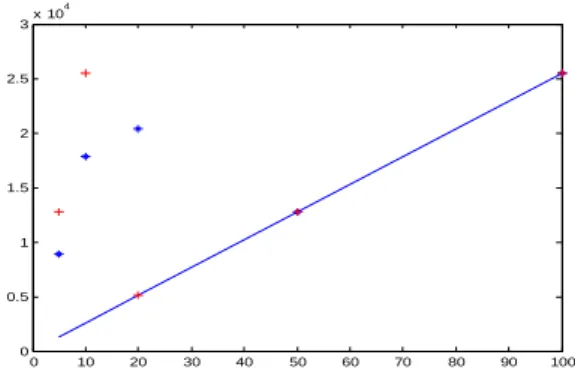
figure, the continuous line presents the minimal cycle length that is proportional to delta as verified in section 3. The experimental results of cycle length are always bigger or equal to the expected one. Figure 4 shows the cycle length of perturbed PWLCM (*) and the (n,t)-tailed shifts map (+) versus the perturbation degree k. Clearly, we can see that the experimental results verify the theoretical one. We found a very large cycle length with a lower bound given by equation (17) and represented by the continuous curve. The perturbation of Frey map gives a large cycle
length (>105) with different values of k and ∆. In the
other hand, to verify the balance property, a set of 500
sequences for each chaotic generator are computed, each
sequence containing 100000 chaotic values. It is already
verified that the balance property of PWLCM is better than the case of Logistic map [3], being slightly different from uniform one. Figures 5(a) and 5(b) show the percentages of zeros and ones of PWLM and perturbed one, and verify that the sequences based on the PWLCM map have a visibly larger percentage of ones.
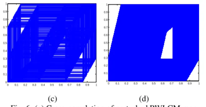
Also for perturbed Frey map and (n,t)-tailed shifts map, the percentage of zeros and ones is closely the same. Then, perturbed maps have a much better uniformity relatively to the original maps. In figure 6(a), the cross-correlation of two sequences with identical initial conditions but slightly different control parameters, is given for the perturbed Frey map. And it is the same result for the other maps. Perturbed Frey generator gives close results as perturbed PWLCM, its attractor shown in figure 6.c contains more free space than that of the perturbed PWLCM and (n, t)- tailed shifts map and shown in figure 5.b and 5.d, and then redundancy code can be used.
0 10 20 30 40 50 60 70 80 90 100
0 0.5 1 1.5 2 2.5
3x 10 4
Fig. 3: Perturbed PWLCM cycle length versus with two different keys; (-): Theoretical results. (*): Experimental results with an initial condition equal to 0.4 and control parameter equal to 0.3. (+): Experimental results with an initial condition equal to
0 2 4 6 8 10 12 0
1 2 3 4 5 6 7 8 9 10x 10
4
Fig. 4: Cycle length versus the perturbation degree k with =10 for Perturbed PWLCM (*) and (n,t)-tailed shifts
map (+).
0 50 100 150 200 250 300 350 400 450 500
0.485 0.49 0.495 0.5 0.505 0.51 0.515
0 50 100 150 200 250 300 350 400 450 500
0.485 0.49 0.495 0.5 0.505 0.51 0.515
(a) (b)
Fig. 5: Balance property (a)PWLCM map, (b) Perturbed m ap .
-8 -6 -4 -2 0 2 4 6 8 x 10⁴
-1 -0.8 -0.6 -0.4 -0.2 0 0.2 0.4 0.6 0.8 1
0 0.1 0.2 0.3 0.4 0.5 0.6 0.7 0.8 0.9 1 0
0.1 0.2 0.3 0.4 0.5 0.6 0.7 0.8 0.9 1
(a) (b)
0 0.1 0.2 0.3 0.4 0.5 0.6 0.7 0.8 0.9 1 0
0.1 0.2 0.3 0.4 0.5 0.6 0.7 0.8 0.9 1
attracteur
0 0.1 0.2 0.3 0.4 0.5 0.6 0.7 0.8 0.9 1 0
0.1 0.2 0.3 0.4 0.5 0.6 0.7 0.8 0.9 1
(c) (d)
Fig. 6: (a) Cross-correlation of perturbed PWLCM map, (b) and (c) Attractors of Perturbed PWLCM map, Frey map and
(n,t)-tailed shifts map respectively.
Nist Statistical Test
Among the numerous standard tests for pseudo-randomness, a convincing way to show the randomness of the produced sequences is to confront them to the NIST Statistical Test (National Institute of Standards and Technology). The NIST statistical test [14] is a statistical package consisting of 16 tests that were developed to test the randomness of arbitrary long binary sequences produced by either hardware or software based
cryptographic random or pseudorandom number
generators. These tests focus on a variety different types of non-randomness that could exist in a sequence.
To verify our results, we employ the above tests suite to test the randomness of 100 binary sequences of length 38912. Note that the 100 binary sequences were generated with randomly selected secret keys. For each test, the
default significance level α=0.01 was used, at the same
time a set of P-values, which is corresponding to the set of
sequences, is produced. Each sequence is called success if
the corresponding P-value satisfies the condition P-value
≥α, and is called failure otherwise.
Table1.
Performed tests and number of sequences passing each test in a sample of 100 sequences.
Number of Passed Sequences Map name
Name of Test
(n,t)-tailed shifts map
Perturbed (n,t)-tailed shifts map
Frey Perturbed Frey PWLCM Perturbed
PWLCM
Frequency 99 100 96 100 97 100
Block Frequency 100 100 96 99 96 99
Cumulative Sums 98 100 92 100 97 98
Runs 99 100 97 98 100 99
Rank 100 100 100 97 99 99
Discrete Fourier Transform
100 95 0 99 99 99
Serial1 97 100 98 100 98 100
Serial2 98 99 99 100 100 100
Approximate Entropy
97 99 94 97 97 100
Percent of 0
In [5], the authors showed that logistic map does not satisfy the requirements as a good random source.
In Table 1, we show the results obtained with the
application of NIST test on PWLCM, Frey and (n,t)-tailed
shifts maps and the comparison with the results of perturbed ones.
As we can see, the perturbed maps are much better than original maps; that the sequences passed all the most of NIST tests. Then, the obtained results demonstrate the strength of the perturbation technique proposed. Since the perturbed maps pass all chosen NIST tests.
V. CONCLUSION
In a cryptographic system, the use of a good chaotic generator, with desirable dynamical statistical properties, is very important. We proved this idea in our previous paper [4]. In this paper, we have implemented six one dimensional chaotic generators (PWLCM, perturbed
PWLCM, Frey, perturbed Frey, (n,t)-tailed shifts map and
perturbed one). And we tested all generators with the application of NIST statistical tests. A comparison among these maps using standard criteria proves the efficiency of the perturbed technique. Indeed, both theoretical and experimental analyses demonstrated that perturbed maps have desired cryptography properties. As prospect of this work, we propose the use of 3 and 4 delays in Frey generator to obtain better dynamical statistical properties. And finally test another chaotic maps perturbed in the same way to find the best cryptographic properties.
APPENDIX
Theoretical analysis of expanded cycle length
Assume that the system has entered a period T state after
n0 iterations, i.e. x n Ti( + )=x ni( )
(
for n > n ; 10 ≤ ≤i N)
and1 1 0
n = × ∆ >l n (l1 is a positive integer), then
1 1
( ) ( )
i i
x n+ =T x n for 1≤ ≤i N. IfT l≠ ×∆ (l is a positive
integer), the above equation implies
1 1 1
[ (i 1 )] [ (i 1)] N i( )
F x n− +T =F x n− ⊕Q− l (for N k− + ≤ ≤1 i N). Since
period T is defined as F x n[ (i 1− +1 T)]=F x n[ (i 1−1)] for
(1≤ ≤i N), thus, QN i−( )l1 =0 (for N− + ≤ ≤k 1 i N).
Because the initial sequences Q Q0, 1,...,Qk−1 are not all
zeros, the previous case will not occur. This implies that
we only have T = × ∆l , which
meansF x n[ (i 1− +1 T)]⊕QN i−(l+l1)=F x n[ (i 1− ⊕1)] QN i−( )l1
(for N− + ≤ ≤k 1 i N). As a result, we find
1 1
( ) ( )
N i N i
Q − l+ =l Q − l (for N− + ≤ ≤k 1 i N). This implies:
( )
2k 1l=σ − where σ is a positive integer. Therefore the
system cycle length is given by: T= × ∆ ×σ (2k−1) and
min (2 1)
L
T = ∆ × − is the lower bound of the system cycle
length.
REFERENCES
[1].D. R. Frey, “Chaotic digital encoding: an approach to secure communications,”IEEE Transactions on Circuits and Systems II, vol. 40, pp. 660-666, 1993.
[2].S. El Assad, C.Vladeanu, “Digital chaotic codec for DS-CDMA Communication Systems,” Lebanese Science Journal, vol. 7, No. 2, 2006.
[3].D. Socek, S. Li, S. M. Spyros, B. Furht, “Enhanced 1-D Chaotic Key Based Algorithm for Image Encryption,” IEEE, Security and Privacy for Emerging Areas in Communications Networks, 2005. [4].Abir Awad, Safwan El Assad, Daniel Carragata . “A Robust
Cryptosystem Based Chaos for Secure Data”. IEEE , International Symposium on Image/Video communications over fixed and mobile networks. Bilbao,spain 2008.
[5].Chengqing Li, Shujun Li, Gonzalo Alvarez, Guanrong Chen and Kwok_Tung Lo. “Cryptanalysis of two chaotic encryption schemes based on circular bit shift and XOR operations”. Physics Letters A, 2007.
[6].Calin Vladeau, Safwan El Assad, Abir Awad. “Optimum Chaotic Quantized Sequences for Chip Synchronous DS CDMA System”. MCSEAI, Agadir, Morroco, 2006.
[7].Pascal Chargé, Danièle Fournier Prunaret, Véronique Guglielmi. “Features analysis of a parametric PWL chaotic map and its utilization for secure transmissions”. Elsevier. Chaos, Solitons and Fractals,2008.
[8].H. Zhou, “A design methodology of chaotic stream ciphers and the realization problems in finite precision,” Ph.D. thesis, Department of Electrical Engineering, Fudan University, Shanghai, China 1996.
[9].R. Rovatti, G. Mazzini, G. Setti, “A Tensor Approach to Higher Order Expectations of Quantized Chaotic Trajectories – Part I: General Theory and Specialization to Piecewise-Affine Markov Maps”, IEEE Trans. on Circuits and Systems – I, vol. 47, no. 11, pp. 1571-1583, Nov. 2000. [10].Li. Shujun, “Analyses and New Designs of Digital Chaotic
Ciphers,” PhD thesis, School of Electronic and Information Engineering, Xi'an Jiaotong University, 2003.
[11].B. V. Chirkikov, F. Vivaldi, “An algorithm view of pseudo chaos,”
Physica D, 129 (3-4): pp. 223-235, 1999.
[12].S. Tao, W. Ruilli, Y. Yixun, “Perturbance based algorithm to expand cycle length of chaotic key stream,” Electronics Letters, 34(9):pp. 873-874, 1998.
[13].S. El Assad, “ Communications Numériques: Techniques Avancées ,” cours 5ème année, à Polytech’Nantes, 2008.