HYBRID WIND-POWER-DISTILLATION PLANT
by
Neven NINI] a, Branko KLARIN b, and Ivan TOLJ a* a
Department of Thermodynamics and Heat Engineering, Faculty of Electrical Engineering, Mechanical Engineering and Naval Architecture, University of Split, Split, Croatia b Department of Fluid Mechanics, Faculty of Electrical Engineering, Mechanical Engineering and
Naval Architecture, University of Split, Split, Croatia
Original scientific paper DOI: 10.2298/TSCI111022032N
This paper reports and elaborates on the idea of a solar distiller and an off-shore wind power plant operating together. The subject under discussion is a single--stage solar distillation plant with vaporization, using adiabatic expansion in the gravitational field inside a wind power plant supporting column. This scheme di-vides investment costs for electric power and distillate production. In the region of the Adriatic Sea, all electric power produced could be “converted” to hydr o-gen using less than 10% of the distillate produced.
Key words:hybrid wind-power-distillation plant, reversible flashing process, integrated systems, renewable energy
Introduction
Distilled water is widely used in the chemical and food industries, as additional supply water for steam boilers, for onboard consumption on ships and for the production of hydrogen and oxygen by means of electrolysis. There is a greater number of seawater stills, but multi-stage flash distillation plants produce 64% of all desalinated water in the world.
The seawater warmed up inside these plants usually enters the first evaporator, where only a small percentage evaporates due to the heat of hot steam produced from an industrial process co-located with the distillation plant or from a cogeneration configuration.
Thus, the steam created condenses in the evaporator chamber and preheats the incoming seawater. The none-vaporated water remaining in the first evaporator is throttled down to a lower pressure in the second evaporator, where additional steam is generated adiabatically; this process is repeated in other adiabatic evaporators until the remaining hot brine water is sufficiently cooled. For the smallest possible consumption of hot steam, it is worth building a great number of evaporator stages in this type of large-capacity still. It is also important for the steam-heat source to have the lowest possible temperature, i. e., the lowest availability, to achieve the highest possible efficiency of the whole, possibly cogenerating, plant.
There are many papers in the literature which deals with seawater desalination systems driven by renewable energies.
Reali et al. [1] presented basic technological features of simple solar stills utilizing tubes for sea water desalting. The evaporation section comprises horizontal transparent thin--walled plastic half-filled with sea water which absorbs solar radiation. The condensation section is physically separated from the evaporation section, in a shaded space below it, and comprises horizontal plastic or metal tubes.
Velmurugan et al. [2] attempt to enhance the productivity of the solar stills by connecting a mini solar pond, stepped solar still and a single basin solar still in series. They also perform an experiment by replacing the single basin solar still into a wick type solar still and study day and night productivity.
Nakatake et al. [3] proposed a newly designed, maritime lifesaving small distiller consisting of a windmill and a number of horizontal concentric cylindrical partitions in contact with saline-soaked wicks. The proposed distiller can be driven by wind only, without human power or electricity.
Eltawil et al. [4] presents a hybrid desalination system that constitutes of wind
turbine and inclined solar water distillation integrated with main solar still. A small wind
turbine is used to operate a rotating shaft fitted in the main solar still to break boundary layer of the basin water surface.
Dev et al. [5] performed an experimental study of inverted absorber solar still and single slope solar still at different water depth and total dissolved solid.
Kalogirou in [6] covers a large variety of systems used to convert seawater into fresh water suitable for human use. Paper also covers a variety of systems, which can be used to harness renewable energy sources; these include solar collectors, photovoltaics, solar ponds, and geothermal energy. Also some general guidelines are given for selection of desalination and renewable energy systems.
Review and state-of-the-art of the most important developments of the wind power desalination is presented by Ma et al. [7].
Disintegration of fluid in two phases in a gravitational field
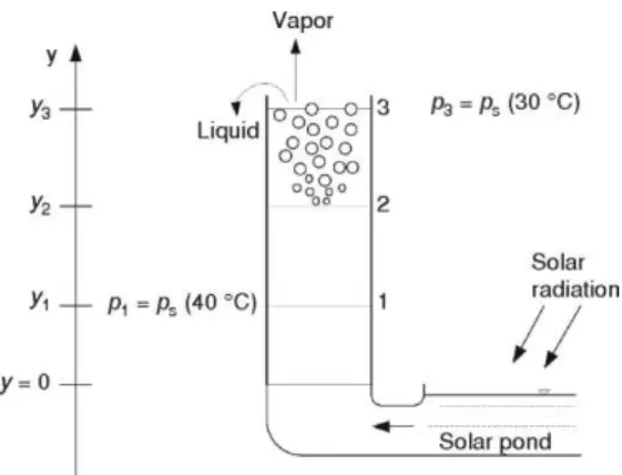
This process begins in the hot updraft flow at the height of the y2 column (fig. 1.), where the first nucleation of vapor in the superheated liquid occurs. In the figure, “1” marks the state in which the pressure of the hot liquid is equal to the saturation pressure at that temperature. The disintegration of the superheated liquid into two phases, with the occurrence of the first sustainable bubble whose radius is greater than the critical value, corresponds to state “2”. The disintegration process ends with state “3”, in which the vapor phase separates from the liquid and rises toward the wall of the turbine supporting column, upon which it
condenses. The cooled liquid that rose to the level of column y3 flows over the edge and falls down to the descending pipe and further on to the pond. The numerical data given in the figure refer to a hot water temperature of 40 °C and a cooled water temperature of 30 °C.
The 1-2-3 process is generally shown in the h-s diagram of stable states close to the saturated-liquid line x = 0 in fig. 2. State 2 is not in the normal h-s diagram of stable states but rather in the metastable state of superheated liquid. State 3s is a fictive state that would be obtained by an equilibrium adiabatic expansion, unlike the actual disintegration process, which ends with state 3. The diagram shows the relationships between the changes in enthalpy and the heights in the column required by the first law of thermodynamics, that is:
h + gy = const. (1)
for all parts of the process. The kinetic energy of turbulent motion in all of the stages is shown as dissipated. In part 2-3, there is also the internal frictional work between the steam bubbles and liquid, which is essential for raising the liquid over the column upper edge.
In the original paper [8], the whole 1-3 process can be described by the term “re -versible flashing process“. Strictly speaking, it is the case in its smaller part for the existence of only a small enthalpy decrease h1 – h3
equal to the potential energy increase g(y3– – y1). There is no such transformation of enthalpy into potential energy of the outer field in a conventional flashing process, such as throttling.
The h-s diagram in fig. 2 shows an actual 1-2-3 process and a fictive 1-2-3s3 process, where the actual process is modeled by breaking it into a 1-2-3s reversible process and an irreversible process 3s-3, which leads to the work obtained in 2-3s as frictional work in the 3s-3 process. The efficient work spent for the potential energy increase is g(y3–y1), part of
Figure 1. Hot liquid states in the vertical column
which is g(y3–y2). accompanied by frictional work in zone 2-3, equal to h3– h3s.
It is assumed that the first supercritical bubble will occur when the liquid is superheated by 5.0 K, therefore, at the pressure corresponding to the saturation pressure at 35.0 °C. The definiteness of states 1, 2, 3s, and 3 ensures that the specific internal friction work during disintegration can be estimated as T3(s3–s2), specifically:
wf2,3 = 303(s3–s1) = 600 J/kg (2)
On the other hand, the total integral 13v pd is roughly:
1 3 (40 C) (30 C)
( )( )
882 J/kg 2
s s
v v p p
(3)
This equation generally has a good correspondence with eq. (2) because this integral expresses the sum of the internal friction work and the kinetic and potential energy changes.
Hybrid wind-power-distillation plant scheme
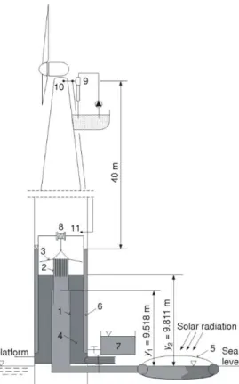
Figures 3, 4, and 5 show the basic construction of an off-shore wind-power-distilla-tion plant [9]. The wind turbine support column is immerged in the sea with its lower part and moored while at sea level, a floating closed shallow pond – the solar collector – is connected to it. The hot water outlet from the pond is connected with a hot water vertical column inside the support column, (1), as shown in fig. 3. By means of its telescopic extension, (2), and its pulling and pushing device, (8),this column has a changeable height.
In the stationary state, the still operates by maintaining a sufficient sub-pressure in the upper part of the support column hol-low, and the hot seawater moves upward along the vertical column and its telescopic extension. The generated steam goes up-ward and condenses while the non-eva-porated cooled liquid overflows from the extension, (2), to the surrounding column annular space, (4). From there, it returns to the pond, (5), to be warmed up. According to the scheme given in fig. 4, cold seawater is added to this pond to replace the produced condensate-distillate and for the permanent brine outlet, which is necessary to maintain the allowed constant amount of salt dissolved in the pond.
As stated previously, the condensate is created by vapor condensation upon the upper internal surface of the plant support column. It flows down to the space with an annular cross-section, (6), as shown in fig.
3; from here, it is drained as a final product under hydrostatic pressure, (7). The sub-pressure is maintained in the steam space by heat transfer from the outer column surface and by a vacuum pump, (9), which ejects noncondensable gases.
Non-condensable gas inlets are placed close to the top of the column, (10), and immediately above the condensate surface, (11). The hot water column height changeability is necessary due to the different operating temperatures of the pond water, and it can be achieved by means of an electric motor and a chain drum, (8).
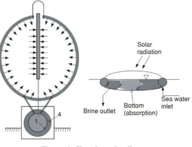
The shallow pond-collector can be a partly inflated floating structure with a transparent cover and pipes con-nected to a hot water column, (1), and the cooled water annular space in the column, (4), as shown in fig. 3. The cooled water pipe that feeds the pond is integrated in the pond as a periphery canal system (fig. 4) with many inlet openings to the pond, close to its bottom.
Thus, cooled water fills the lower part of the pond, near the bottom; the hot water outlet from the pond goes through a system of openings leading to the outlet pipe through the middle
of the pond (fig. 4). These openings are closer to the water surface in the pond. Finally, a device near the pond lets in the surrounding seawater into the pond at an amount equal to the distillate and brine outlet flow produced. The device is based on a floating body reacting to a change in the water level in the pond. The transparent cover can float on the pond water surface and is in the form of two thin foils with closed air cells in between.
Operating conditions in the still
To provide insight into the overall size and capacity of the wind-power-distillation plant, the central Adriatic region was chosen for an average day in January and one in July.
According to [10], in January, the mean temperature for the central Adriatic region is 9.7 °C. According to [11], between 1000 and 1500 hours, the mean temperature for the area relatively close to Dubrovnik is about 1.0 °C higher than the daily mean temperature. It is therefore assumed that, for this approximate calculation, the mean temperature during the use of solar power is tos = 10.7 °C.
On the other hand, the total solar irradiation per 1 m2 of a horizontal plate is about 1.80 kWh per day. The radiation actually begins at 830 hours and lasts until 1615. The plant is assumed to be in the quasi-stationary regime from 1000 to 1500 hours. The part of the total radiation corresponding to this period of the day is calculated to define its average power. According to the known arrangement of the total radiation intensity for a particular latitude, for the stated operation period of 5 hours, we obtain 85% of the total irradiated energy, with an average intensity of:
2
0 85 1800
306 W m 5
.
G /
For an average day in July, the daily mean temperature is 24.0 °C; the mean temperature between 800 and 1900 hours is approximately 1.5 °C higher than the daily mean, and therefore tos = 25.5 °C. The total solar irradiation is 7.4 kWh/m2 per day. The radiation actually begins at 500 hours and ends at 1900. We use the plant in the quasi-stationary regime from 700 to 1800. According to the known daily radiation schedule, for the stated operation period of 11 hours, the mean radiation intensity is:
2
0 85 7400
572 W m 11
.
G /
Collector efficiency
The pond-collector efficiency is defined as the ratio of heat received and the total radiation available at the collector surface. For the characteristic circumstances described, the efficiency depends on the hot water temperature and the temperature decrease in the column-evaporator. We chose 40.0 °C as the characteristic hot water temperature for January and 30.0 °C as the temperature after its adiabatic evaporation. Thus, the water is superheated after the pressure decreases in the evaporator at 10 °C, which is within the recommended values. The assumed hot water temperature is not optimal; however, the results will give a reliable insight into the maximum possible capacity of the still and the influence of certain operating parameters on its capacity.
The efficiency depends on the ratio (tabs –tos)/G at the abscissa and on the collector type. According to [12], for the assumed circumstances and for water at distiller temperatures of 40/30 °C, the efficiency is negligibly small if the shallow pond is open. For a pond closed by a one-layer transparent cover with glass characteristics and an absorbing bottom, the ratio (tabs – tos)/G is 0.079 while the efficiency is approximately 0.30. The water temperatures assumed for July are 55/45 °C. In this case, the ratio (tabs –tos)/G for the efficiency is 0.043, and the efficiency is approximately 0.53. Both efficiencies are 10% lower then according to diagram in [12]. The reason for that are specifics off-shore circumstances.
Working parameters in characteristic regimes
During the quasi-stationary regime in January, the hot water saturation pressure is ps(40°C) = 7380 Pa. For an atmospheric pressure of 100000 Pa, there is a corresponding sub-pressure of 92600 Pa, and the height above the water level in the pond is y1 = y(40) = 9.518 m. For a cooled water saturation temperature of 30.0 °C, y2 = y(40) = 9.811 m. These two water level heights are shown in fig. 3 for static conditions, neglecting hydraulic pressure losses.
During the quasi-stationary regime in July, the saturation pressures are ps(55°C) = = 15740 Pa and ps(45°C) = 9582 Pa while the corresponding hot water column height is y(55) = = 8.72 m.
For the regime in January, the evaporated water flow mv is part of the hot water inflow from the pond to the column mhw, mv(30 C) xmhw while the evaporated part x is determined from the energy balance before and after the adiabatic disintegration of hot water into two phases. Neglecting the potential energy changes, this balance becomes an enthalpy balance:
hw (40 °C) hw(1 ) (30 °C) hw (30 °C)
It follows that the evaporated portion of hot water is x = x3 = 0.0172 (fig. 1). With this value, the specific volume of the homogenous two-phase flow at the top of the column is:
v3 = 0.567 m3/kg (5)
Analogous to this calculation, for the July regime, it is:
(55 °C) (1 ) (45 °C) (45 °C)
h x h xh (6)
and
x = 0.0175 as well as
v3 = 0.343 m3/kg (7)
The corresponding steam flows, i.e., the distillate flows, depend on the bottleneck in the still capacity. This bottleneck is represented by the condenser surface and the condenser heat transfer coefficient, as well as the total temperature difference over the condenser wall. For January, the heat transfer through the condenser wall is:
c c (30 10.7)
Q A k (8)
The condenser area is equal to the area of the supporting column upper part. For a 3.0 m average diameter and 40.0 m height, this area is Ac = 3p40 = 377 m2.
The heat transfer coefficient is:
out in
1 1 δ 1
k α λ α (9)
where aout is the heat transfer coefficient on the outer side of the column. According to the empirical formula in [13]:
aout = 5.7 + 3.8w (10)
where w [ms–1] is the wind speed and w = 6.0 m/s. It follows that:
aout 28.5 W/m 2
K
Furthermore, the heat resistance of the heat transfer through the column steel wall and the resistance for the condensation on the inside are neglected. For an outer resistance coefficient 1/αout = 0.0585, it becomes:
0.020
0.0004 0.0585 50
δ λ and
in
1 1
0.00011 0.0585 9000
α
A relatively high condensation heat transfer coefficient αin in this estimation is appropriate for relatively small heat flows, determined only by the outer heat transfer resistance. Thus, the results are small, and the heat transfer into space by means of radiation is not calculated. It would increase Qc by approx. 18% (January). Therefore, assuming k≈ αout, it follows that:
377 28.5 19.3 207369 W c
The steam flow is:
3 v
(30 °C) (30 °C)
207.3
0.085 kg/s (approx. 1.5 m distillate per day)
m
h h
Let us now turn to the July regime. Heat flow is:
c 377 28 5(45 25 5) 209517 W
Q . .
The steam flow is:
v
(45 C) (45 C)
209 5
0 087 kg s
.
m . /
h h (approx. 3.4 m3 distillate per day)
The necessary pond–collector size
The January regime requires a pond with an area of Acoll such that the heat received in, Qp:
p c coll coll
Q Q A Gη [W] (11)
For Qc, G, and ηcoll in January, it follows that Acoll = 2260 m 2
. For Qc, G, and ηcoll in July, it follows that Acoll = 691 m
2 . For further estimations, we assume that Acoll = 2000 m2.
The start up of the plant and the nocturnal regime
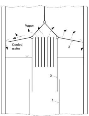
The plant begins by warming the water in the pond and then exhausting the air from the supporting column hollow by the vacuum pump. Thus, there is no water in the lower part of the supporting column hollow, and the tubes connecting the ascending column and descending annular channel with the pond-collector are shut by the valves. After obtaining the necessary vacuum in the column hollow and the necessary water temperature in the pond, the valve connecting the pond with the ascending column, (1) in fig. 3, opens, and hot water rises along the ascending column. At the height y1 (fig. 1), the first steam bubbles occur, and in the upper part of this column, within the cluster of channels in its telescopic extension, (2) (fig. 3), the two phases originate. The steam separates and rises, and the liquid flows over to the descending annular channel, (4) (fig. 3). The valve on the liquid return pipe opens, establishing a stationary flow of hot water upward as the cooled liquid returns back to the pond. The steam goes further upward while the condensate descends along the column wall to the condensate annular channel, (6), and to the condensate tank, (7) (fig. 3).
the saturation temperature in the steam space falls below approximately 5 °C, the boiling process in the telescopic extension channels stops. The circulation of hot and cooled water will decrease greatly, yet it will continue due to the maintenance of at least a small difference in temperature in the ascending and descending column-channel. To maintain such a low tempera-ture difference of few degrees centigrade, the ascending column and telescopic extension walls should be made of an appropriate material or should be heat-insulated. The process of steam extraction from hot water occurs as the water flows over the plate flange, (3), as shown in fig. 3 and 5.
The nocturnal regime with very low circulation intensity has only one practical purpose: the maintenance of circulation. It will cause the temperature in the ascending column to increase again at sunrise.
Therefore, when it is 5 or 6 °C higher than the saturation steam temperature in the column, the boiling process will automatically be established again in the telescopic extension, the circulation will increase, and the intensive working regime of circulation and steam generation with two-phase flow will be established.
Relationship between the produced distillate and the wind turbine electric work
We assume 2500 kW for the nominal wind turbine power with a working time of 1800 hours per year for the central Adriatic region. Thus, an average of 12329 kWh is produced each day, and the mean power at the generator terminals is 514 kW during a 24-hour period. The value of 1 kWh at this power plant threshold is somewhat smaller than the price for consumers and is approximately 0.10 € per kWh. This amount corresponds to approximately 1230 € per day. The simultaneous daily mean production of distilled water is approximately 2500 kg per day. With the distillate retail price of 0.8 € per kg, our estimate of the wholesale would be 0.400 € per kg. The value of the daily produced distillate would therefore be approximately 1010 € per day, or approximately 75% of the value of the electrical work generated (electrical energy).
The amount of rainwater collected from the covered pond-collector surface is independent of the distillate production and amounts to 300 kg/m2 per year, which is approximately 1640 kg per day in this case.
The production of the distillate occurs at a place where the production of electric energy is unstable. Taking this into account and to avoid transport of that energy to mainland, the best solution might be accumulation of that energy in hydrogen by process of distillate electrolysis.
Let us establish the relation between the amounts of distillates produced and electric energy for their electrolysis. Let us assume that the process is ideal, reversible in the thermodynamic sense, and that, from a distillate at a pressure of 1.0 bar and a temperature of 25.0 °C, H2 and O2 are produced, both at a standard pressure of 1.0 bar and a temperature of 25.0 °C. In this case, the entropy of 1 kmol of water is 69910 J/K. For the 1 kmol of H2, produced the entropy is 130570 J/K, and for 1/2 kmol O2, the entropy is 102500 J/K. The heat brought from the ambient is, in this case, ToDSs = 298.15(130570 + 102500 – 69910) =
= 48646154 J/kmol = 2702564 J/kg of water. The energy balance of the ideal electrolyzer include enthalpy of destilate, heat brought from the ambient and electrical work generated by wind turbine as input flows, gives:
2 2
o o o
d d d d O d H
16 2
2703 514
18 18
m h m m h m h (12)
or
d
514
0 001816 283097
m . kg/s = 157 kg per day
The amount of distillate used in this way is only approximately 6% of the quantity produced. In the actual electrolytic process, the heat is not taken from the ambient. Instead, the increased entropy in the reaction is covered by dissipated electrical work, and the actual electrical energy spent is approximately 50-60% greater than the theoretical value. According to that the quantity of destilate for hydrogen production is approximately 4% of the quantity produced.
Conclusions
The distillation of seawater in the one-stage hybrid plant described herein is technologically simple and economically justified because an already existing wind power plant structure is adapted for distillate production. The distillate production inside the wind turbine support column is almost a self-sustaining process, i. e., the process requires a relatively small additional power for start up and vacuum maintenance (vacuum pump drive).
Nomenclature
A – area, [m2]
h – enthalpy, [kJkg–1]
G – total solar irradiation, [Wm–2] g – gravitational acceleration, [ms–2]
k – overall heat transfer coefficient,
– [Wm–2K–1]
m – mass flow, [kgs–1]
p – pressure, [Pa]
Q – rate of heat flow, [W]
S – entropy, [Jkmol–1K–1]
DSs – entropy increase due to irreversibility,
– [Jkmol–1K–1]
s – entropy, [Jkg–1K–1]
T – absolutetemperature, [K]
To – standard temperature, [K]
t – temperature in Celsius, [°C]
v – specific volume, [m3kg–1]
w – wind velocity, [ms–1]
wf – specificfrictional work, [Jkg–1]
x – vapor quality, [–]
y – height, [m] Greek symbols
a – convectiveheattransfercoefficient,
– [Wm–2K–1] δ – thickness, [m]
λ – thermal conductivity, [Wm–1K–1]
References
[1] Reali, M., Modica, G., Solar Stills Made with Tubes for Sea Water Desalting, Desalination, 220 (2008), 1-3, pp. 626-632
[2] Velmurugan, V., et al., Integrated Performance of Stepped and Single Basin Solar Stills with Mini Solar Pond, Desalination, 249 (2009), 3, pp. 902-909
[3] Nakatake, Y., Tanaka, H., A New Maritime Lifesaving Distiller Driven by Wind, Desalination, 177
(2005), 1-3, pp. 31-42
[4] Eltawil, M. A., Zhengming Z., Wind Turbine-Inclined Still Collector Integration with Solar Still for Brackish Water Desalination, Desalination, 249 (2009), 2, pp. 490-497
[5] Dev, R., Abdul-Wahab, S. A, Tiwari, G. N., Performance Study of the Inverted Absorber Solar Still with Water Depth and Total Dissolved Solid, Applied Energy, 88 (2011), 1, pp. 252-264
[6] Kalogirou S. A., Seawater Desalination Using Renewable Energy Sources, Progress in Energy and Combustion Science, 31 (2005), 3, pp. 242-281
[7] Ma, Q., Lu, H., Wind Energy Technologies Integrated with Desalination Systems: Review and State-of-the-Art, Desalination, 277 (2011), 1-3, pp. 274-280
[8] Ninić, N. et al., Desalination with a Reversible Flashing Process, Desalination, 89 (1993), 3, pp. 263- 273
[9] Ninić, N., Klarin, B., Tolj, I., Off-shore Hybrid Wind Power-Distillation Plant, Patent Application P20110545A, 2011
[10] Matić, Z., Solar Radiation Data in the Republic of Croatia (in Croatian), Croatian Energy Institute "Hrvoje Pozar", Zagreb, 2005
[11] Galo, B., General and Traffic Metereology: Part 1 (in Croatian), Skolska knjiga, Zagreb, 1994 [12] Viessman: Design Instructions, 8/2007
[13] Kreith, F., Kreider, J., Principles of Solar Engineering, Mc. Graw-Hill Book Company, New York, USA, 1978
Paper submitted: October 22, 2011 Paper revised: January 23, 2012 Paper accepted: February 1, 2012 Subscripts
abs – absorber of radiant energy c – condenser
coll – collector d – distilled water in – inner hw – hot water out – outer
OS – atmospheric environment
s – saturation v – vapor Superscripts