Abstract—this research proved the feasibility of establishing the isolative power supply system of hybrid wind power in terminal substation, so as to enlarge more wind power in a power system. To avoid affecting main power system, wind power is installed on low voltage bus of terminal substation. The simulation testes system stability under different wind speed and the switching process and short circuit, and verify the limit value of wind power in power system. To realize the isolative power unit,the control system is applied for terminal substation with micro-grid.
Index Terms-- enlarge wind power, terminal substation, smart micro-grid, stability simulation, isolative operation control.
I. INTRODUCTION
To enlarge wind power capacity in a highly-hybrid wind power system has become very important question for power administrators in windy area. However, any power system has a finite capacity to accept wind power; excessive wind power brings great influence on electric quality by lowering system frequency and voltage. In our case, although advanced permanent magnet generator and the frequency conversion equipment have greatly reduced the impact of wind power, the simulation proved that power system may lose stability if the proportion of wind power reaches 15% of system capacity, currently, the percentage accounted over 12.8% in the power pool, therefore the power system runs with highly-hybrid and near the limit of wind power as many systems are doing. With the rapid development of economy and traditional industries, the demand of electric power becomes more and more great. However, popular tourism destination need limit thermal power and develop clean energy so that to protect the precious ecology and water resources of this arid area [1].
Considering the power system is already nearing its limit to integrate wind power, two methods were adopted to enlarge wind power while maintaining the electric quality: (1) (being performed) use advanced and large-scaled wind turbine with permanent magnet generator with reactive power compensator in 110kV and 220kV substations, (2) (new proposal, not yet performed) install an appropriate wind power in low-voltage terminal substations, such as 10kV and 35kV end substations. Local Power Developing Plan requires
Financial support of this research is from National Natural Science Foundation of China with Grand Number: 41261107 and the Fund of the Key Research Center of Humanities and Social Sciences in the general Colleges and Universities of Xinjiang Uygur Autonomous Region..
Zulati Litifu is with the Statistics and Information Institute of Xinjiang University of Finances and Economics, No. 449 Middle Beijing Road, Urumqi, 830012 China. (Phone:86-991-78433746; e-mail: zulati@
25.6% of wind power in power system by the end of 2015, and
both approaches can contribute to this target; however, the peoples express strong hopes of high power quality, low cost and good safety. Our comparative analysis reveals that method (1) is the most effective way even if the high cost of performance. Equally important, the theoretical feasibility of (2) is worthy to be attempted due to its low cost and high efficiency, this paper mainly focuses on this practical problem supported by local government and National Natural Science Foundation.
II. LOCAL POWER SYSTEM AND WIND POWER CONNECTION
Like the regional power system existing in the developing countries in the world, this power system mainly services for the agricultural and local industrial parks. The proportion of local secondary industry rapidly reaches 64% in 2013, and it becomes one of the major loads of local power system.
A. The Characteristics of Existing Power System
Just as mentioned above, the target local power system is running near limit value of wind power. External power from the three thermal power plants integrates into the local power system with the total capacity of 2310MW and the average distance of 183km. Target region is one of the famous windy zones in Xinjiang Region, wind power reaches 297MW in the power system, which forms 337MW of uncontrollable QV power capacity together with the solar power. Wind and solar farms mostly connect to high voltage substations of 110kV and 220kV and mixed in power pool before distributed it to the local load. There are controllable PV power capacity of 84.64MW distributed by low voltage substations of 10kV and 35kV. Table 1 indicates the annual wind speed and wind power proportion in local power system. Here, 40MW solar power is not counted into the proportion because solar power is more stable than wind power in operation; it doesn’t need reactive power in starting process as wind power did.
TABLE I
WIND POWER CAPACITY IN THE LOCAL POWER SYSTEM
the annual winds peed measured in target area
Month Jan. Feb. Mar. Apr. May Jun. WS[m/s] 7.00 6.40 6.30 7.30 7.40 6.60 Month Jul. Aug. Sept. Oct. Nov. Dec. WS[m/s] 5.90 5.60 5.40 5.50 6.20 7.30 proportion of wind power capacity in local power system
system capacity wind capacity
2394.64MW 297MW
wind power proportion at the end of 2013: 12.40 % planned wind power proportion by the end of 2015:24.80 %
A Research on the Feasibility of Supplying Wind
Power for Industrial-Park at Feeding Terrnimal
B. Establish Wind Power Supply System at the Terminal Substation of Local Power System
According to the field investigation, wind power reaches about 18% of local power system in July 2014; power quality becomes the important problem. Empirically, to install wind power at the terminal substation may have advantages of: (1) form relative independent power unit with the nearest load, which can minimize power loss and improve energy efficiency, (2) easy to use smart micro-grid (SMG) on low voltage side of substation to reduce wind power impact on power system, (3) fully use the wind energy of this windy area. Fig.1 shows wind power connected to low voltage bus in the substation to form relative independent system of hybrid power supply.
wind power farm
12MVA Equivalent system sources
69.3kV terminal bus
22.8kVterminal bus 25MW
2×18MVA
69.3kV/22.8kV substation
Sum of local load from 2MW to 18MW, power factor 0.85
Bus-2 low voltage in substation
W.F-bus Capacity bank
0.23MVAR Short circiut level 70MVA
Bus-1
Figure 1. Wind power connected to the feeding terminal grid of 10kV
Here, low voltage bus indicates 10 and 35kV substations in 220 and 110kV network. To obtain economic and stable efficiency, two connecting ways of wind power were proposed in system terminal substations, the first way is to connect wind power to 35kV bus, this way can be used for feeding heavy load, such as the load of industrial parks, and the second way is to connect wind power to 10kV bus, this way can be used for feeding light load, such as the load of residential and subsidiary units in enterprises. To makes this research more applicable, we use wind power capacity covering the largest industrial load and voltage level 22.8kV between 10 and 35kV as shown in Fig.1. The result of this
study can be used for estimating the condition of 10kV and 35kV substations that widely existing in target region.
III. SIMULATION OF WIND POWER PERFORMANCE
A. Conditions and Concept involved in the Simulation
1) Performance of wind turbine in regular wind speed
Fig.2 and (1) indicate simulative equation and schematic of normal operation in stable and effective wind speed.
in ig gb b p
sg PC k k k k
P
V A
P 0.5 3 (1)
Fig.2 denotes the meaning of some constants used in (1). Here, V and A denotes wind velocity and the swept area by
blades, ρ is air density of installation site and Cp is power
factor of selected wind turbine. In condition of multiple wind turbines, the total generation can be obtained from the sum of each generation. However, the sum of lost reactive power and voltage drop can no longer be linear relation with sum of each turbine, it is difficult to numerically estimate two parameters from linear calculation, in such case, Wind and Generation Matrixes is effective by applying SIMULINK method [2] [3].
sg
P
3 5 . 0 AV
P
Figure 2. The parameters relate to normal operation inside wind turbine
2) Performance of wind turbine in dynamic wind speed
A small variation of wind velocity may be absorbed by blade inertia devices, however, a big variation during a short time period can drive turbine to new operation point through the transient process as shown by matrix function (2).
BV AI pI
BI AE pE
BV A
p
(2)
where; p=d/dt, the letters I,Ψ, V and E stand for current,
magnetic linkages, voltages and electrical potential matrixes.
A is variable matrix related to technical parameters of wind
power turbine, B is additional matrix related to parameters of
voltage and current in the same order as A. Tracking control
way dp/dω=0, the electrical and mechanic equations are both
in dynamic state before being fixed at new operating point. The standard equation for transient simulation is shown in (3), here; C and Dare the output and input constant matrix; (3) is
the linearization state of (2) with the given time frame, or the equivalent equation of state (2). State equation (3) can be linked to SIMULINK and calculated by numeral method [4].
U D X C Y
U B X A X
p (3)
here; C and D are the output and input constant matrix; (3) is
the linearization state and equivalent equation of state (2) in the given time frame or the. State equation (3) can be linked to SIMULINK and calculated by numeral method.
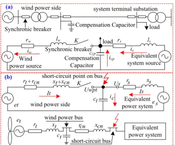
3) Performance of wind turbine in switching process and short circuit situation
There are two key factors to cause transient process in switching operation; they are reactive power and capacity of power system. Due to a limited amount of reactive power, a small scaled power system may suffer from more severe concussion than a big one. Empirically, turbine with capacity less than 100kW, the final numeral result of switching action can be derived from the equivalent circuit in (a) Fig.3, basing on the Power Flow Calculation Technique. But in case of large scaled wind turbine with the capacity over 100kW, the switching process shows strong and complex non-linear properties; hence the SIMULINK Method is more effective.
ar gsc gsc
wpt wpt s
s gsc
U S I
Z U k Z U k S
3
2 2 2
1 (4)
Here, Zs =rs+jxs, Zwpt = rs+rcn+j(xs +xcn). k1 and k2are constant with range from 1.05 to 1.1 according to system voltage level. If short circuit occurs near the output terminal of wind turbine, then we use Zwpt=X"d=x"d (Uwpt)2/Swpt.s. where, Sgsc and Igsc stand for the impact capacity and current through equivalent capacitor ct; Zs and Usare the remained reactance and rated voltage of system side, Zwpt and Uwpt are the remained reactance and rated voltage of wind turbine as shown In (b) Fig.3. Short circuit occurs on stator coil and connection bus of wind turbine, but mostly, it occurs at link-bus of terminal substation due to entered animals and wrong operation.
(a)
ls Synchronic breaker load
rw lw
Ccp
iw is
icp Compensation
Capacitor
Equivalent system source Wind
power source
system terminal substation
load Synchronic breaker
wind power side
Compensation Capacitor
K rs
wind power side power sytemEquivalent short-circuit point on bus
K
et
Is c
i
It Uwpt
t c
s x s r
s e
+
t
r rcn xt+xcn
short-circuit bus
Equivalent power system wind power bus
t c
cn x cn r et
t r xt
(b)
Us
Figure 3. (a) Equivalent transient circuit of connection process (b) Equivalent transient circuit of short circuit situation
4) Limit value of wind power capacity in end substation
The limitation of wind power capacity is the maximum capacity that can be safely accepted by a terminal substation, which can determine the number of wind turbine that can be safely connected to terminal substation. Among the several references to estimate the limitation value, however, the most effective way is the estimation of bus voltage, the permitted variation range should within ±5% of rated system voltage; the frequency and slip are also the references of estimation.
B. Analysis on the Simulation Results
Regional wind speed in table I can drive large and middle sized wind turbine, 600kW turbine is chosen for simulation, which has been widely applied for local power system in many countries with rich using experience. 300 and 500kW turbines are fit candidates for terminal substation; anyway, 600kW turbine needs larger reactive power than small turbines in operation. If terminal substations can sustain 600kW turbine, it certainly sustain the turbines smaller than 600kW. Table II shows the parameters of 600kW turbine. In simulation, the permit ranges are: bus voltage ±5%, system frequency ±2% and slip rate should be within 10% [5].
TABLE II
TECHNIQUE PARAMETERS OF 600KW WIND TURBINE
capacity power factor frequency stator resistance stator reactance
0.6MW 0.912 60Hz 0.0079Ω 0.00017Ω
rotator
resistance rotator reactance Pole Cut-in wind speed Cut-out wind speed 0.0006Ω 0.00017Ω 6 3.2m/s 13.8m/s
Fig.4 shows the normal and dynamic wind speeds used in simulation. Here, the dynamic wind speed is the big gap from 3.5m/s to 13.8m/s in installing site, the normal average wind speed relates to recorded 722hrs wind in a 1 month period.
W
ind
S
pee
d [
m
/s]
0 100 200 300 400 500 600 700
0 4 8 12 16
Time [Hour]
0 5 10 15 20 25 30
0 10 20
Time [Second]
Wind
Speed
[m/s]
(a)
(b)
Figure 4. (a) 720hrs average wind speed in a1 month period in installing site, (b) suddenly changed wind speed from 3.5m/s to 13.8m/s.
The variation of observed parameters in this simulation is shown in table III. In normal operation, local load increases from 2 to 18MW in 722hrs wind speed, the result indicates that a single 600kW turbine operates entirely in a good condition, which shows ability in tightly tracking for the variation of wind speed (curve is omitted due to page limit); active and reactive power and wind speed are tightly in step. (b) in Fig.4 denotes dynamic wind speed, simulation shows the terminal substation is stable in such dynamic wind speed. When turbine connects to the power system, it results in a momentary in-rush of current as magnetic field is energized. This impact current can be limited but not eliminated; one of the methods is to control rotor speed, rotor with zero speed may cause heavier transient than that with a speed as shown in Fig.5. From the simulation, the short circuit proved our breakers can sustain the impact current.
TABLE III
THE VARIATION OF OBSERVED PARAMETERS IN THE SIMULATION
Observed
parameters in regular wind speed (720hrs recorded) in dynamic wind speed (from 3.5m/s to 13.8m/s) Voltage from 674V to 690V (W.F.-bus) from 22.21 to 22.35kV (bus-2 in substation)
frequency[Hz] 59.2Hz to 60.6Hz 60.00 Hz to 60.45Hz
slip [%] -1.2%-0% ———
Observed
parameters switching process (connected to bus 2) short circuit (on the turbine terminal) Voltage from 23.00kV to 21.00kV (bus-2 in substation) from 690V to 0.00V (cut off after 0.02s)
frequency[Hz] 50.4Hz to 65.0Hz (back to 60Hz after 0.04s ) 60.0Hz to 68.0Hz (cut off after 0.02s)
The simulation proved the technique feasibility to enlarge wind power by installing in it terminal substation. Limit value of wind power is estimated by this simulation, at least, one 600kW requires 228kVAR reactive power and five turbines require 1140kVAR, which can be issued by compensator if necessary in practical application. Now, the follow-up of this research is to design the control system so that to form a relative isolative system of terminal substation.
Current A [A]
Cu
rrent B [A]
Figure 5. Impact current of connecting 600kW turbine with the rotor speed (a) at zero (b) at 95% of synchronous speed.
IV. THE CONTROLLING SYSTEM OF TERMINAL SUBSTATION
Terminal controlling system covers stable operations and fault situations, however, the main target is to minimize the impact of wind power on main power system that is operating with 12.4% of wind power, the control method need form the operation model with relative isolation of terminal substation.
A. Control system of one or more wind power sources
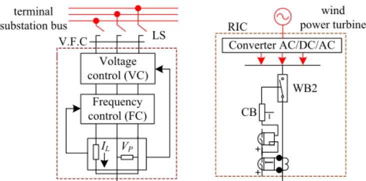
Fig.6 shows designed Regulator and Inverter Controller (R.I.C) and Voltage and Frequency Controller (V.F.C) for controlling wind turbines of 100 to 1000kW used in terminal substations. R.I.C consists two layers of silicon bridge circuit of AD/DC and DC/AC, and R.I.C can form standard power in changing wind speed and includes a over current protection system. V.F.C tracks the voltage and frequency by feedback system of input power and load condition. Not only this control system can cut turbines off when the reactive power verifies and short circuit occurs inside turbine, but also it can adjust the frequency and voltage to make hybrid wind power in high quality and directly drive local load by wind power.
V.F.C LS RICConverter AC/DC/AC
terminal
substation bus power turbinewind
Frequency control (FC) Voltage control (VC)
IL VP
CB
WB2
Figure 6. Designed R.I.C and V.F.C for controlling wind power turbine
B. Control System of Terminal Substation and Wind Farm
In order to reduce affect on main power system, the smart micro-grid controls the operation of terminal substation; Fig.7 is the typical model of substation control system.
Figure 7. Signal control system of smart micro-grid in terminal substation
Smart micro-grid (SMG) has intelligent function to measure the variation of load, wind power and system power. To save cost and maintain devices, the value between 20 to 100W is an reasonal starting value of the signal comparator althoght the value can be much smaller by current technology. SMG adjusts the voltage and frequency again by signal comparator, which can also coordinate the serious situations caused by dynamic wind speed and switching process. V.F.C and R.I.C and SMG can form a isolative operation source of wind hybrid power. Any small changes in wind speed and output power may be tracked and adjusted by frequency and volatge collector so that to fully use wind energy. Almost, the proposed control system may enlarge wind power ratio in power system but without influence on system operation.
C. Relay Protective Devices in Control System
The different operation conditions of terminal substations require different type of relay system. To assure safety, relay parts inside transformers are fully used. To fit for requirement of isolative operation, we frugally use the relay protection of short circuit, overload, over current and low voltage. In this research, low voltage relay acts when bus voltage is lower than 0.7 times rated voltage, in case of the switching process, wind turbine needs more reactive power and lowers bus voltage, which should be stopped by voltage protection. This research suggests setting instantaneous relay protection for important electric device with the action time from 0.04 to 0.08s (that matches for breaker tripping time from 0.06 s to 0.15s). Fig.8 shows the proposed time of backup protection, if short circuit occurs on d-3 but relay 3
refuses to action, then, relay 1 will action after about 0.6s delay with high possibility over 90% (other pictures are omitted due to page limit) [6].
t
t
t
D.
C.sourc
Figure 8. Relay protection system for terminal substation and wind power
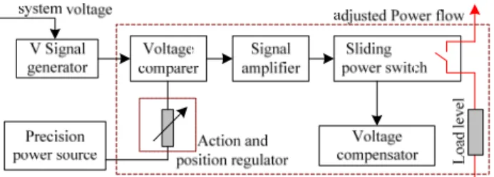
D. Control system for tracking variation of load and power
Fig.9 denotes the intelligent control device using voltage signals of auto-tracking load range at any time. Adjust power supply through compensating bus voltage, this cheap tracking device is suggested to apply for terminal substation.
Figure 9. Operational principle of proposed load tracking device.
In proposed control scheme, the main loads of agriculture industrial and mixed load are considered in substation. Based on statistical operation record, each substation has the change regularity of power and reactive. Hence, the standby power supply controlled by the SMG in Fig.7 may improve system reliability, which power reserve equals to the statistical load demand. Fig.10 denotes the equivalent standby power system that is real-time controlled by SMG tracking variation of load and demanded power. When make Vst>Vgs>Vl,, SMG transfers power for MG on W.F-bus through impedances Z1 and Z2 as shown in Fig.10 (a), the system grid also can provides Qsg for turbine operation. Supposing the voltage and frequency of system grid are fixed (Qsg and Psgmatch for load demand for a fixed time) as shown in Fig.10 (c), the relation of SMGand MGcan be explained by Fig.10 (b) and we have (5):
) (
) (
st l q st l
st l p st l
Q Q k V V
p p k f f
(5)
where, kp and kq are active and reactive power coefficients.
System grid
SMG Standby
power system
MG MG with RIC and VFC
local load
standby bus
Transmission impedance Z2 Vl
Ist
Il
Voltage Frequency
Vs
Vl
Ps Pl
fs fl
Qs Ql
kq kp
Pst, Qst
Ql , Pl
Vst
Z1
SMG MG
Z=Z1+Z2
Vsg
Vst Vl
Pgs Qgs
Psg,Qsg (a)
(c) (b)
Figure 10. The structure of power system whith SMG on standby bus cooperating with MG on W.F-bus
Our resent research proved that the voltage and frequency of MG relate tightly to active and reactive power in transfer as shown in Fig.10 (c). In application, voltage and frequency
can be adjusted based on system control margin, one feasible case is Vst=(1.05-1.1) Vsg=1.0, Vl =(0.95-0.9), fst=0.99 and fl =0.98 (for agricultural load). Determined by system condition, kp [Hz/kW] and kq [kV/ kVAR] have the statistical property of operational record and experience. The (6) can be used for estimating the transferable reactive and active power from SMG to MGunder permit margin in practical operation.
) ( 1
) ( 1
l st q
l st p
V V k Q
f f k P
6
As the experience coefficients, kqand kp closely match for the power system in each country and worth to be continually studied according to system actual operation characteristics.
This paper studied the serious case of 12MW wind power and the load variation from 2 to 18MW in terminal substation, the isolative internal control system enlarges wind power without affecting main power system, which also provides feasible adjustment for active and reactive power in terminal substation, the study result can be applied for estimating more than 200 local terminal substations. And as the result, it is feasible to reach the target of 24.8% wind power in local power system by the end of 2015.
V. CONCLUSION
This proved the feasibility of supplying wind power at the terminal substations of local power system. As mentioned in this paper, the local power system has already been highly hybrid with wind power, it is no safe to increase wind power in main power system. However, by connecting wind power units at the terminal substation and forming independent controlling system, the influence of wind power on the main power system may be largely decreased, and simultaneously, the total wind power in entire power system may be increased in a large degree. This method can be used in the power system that operates with large amount of wind power, and this research may provide the theory basis for wind power development in a windy region.
References
[1] Z. Litifu, Asipjiang, Han Qian, "Investigation of development wind and solar power in Turpan Prefecture," Urimqi, Xinjiang,. May, 2013. [2] Huang Jia Yu, Cheng Li Yi, Numeral Simulation of Electric Power
System, China Power Publication, 1993.
[3] F. L. Alvarado, W. F. Tinney, Scarcity in Large-Scale Network Computation, Academic Press. 1991.
[4] J.Huang, L.Zulati, K. Nagasaka, "Installation of Wind Power into a Weak Power System Considering System Fluctuation and Limitation", WSEAS Transl. Greece, Issue 1, Volume 4, January 2008.
[5] Institute of Power System Design of China, Design Manual of Electric Power System, Vol. I. Electric Power Publisher, Beijing, 1998,
pp.200-500.
[6] Chen Xi, Practical Technology of Wind Power System, Beijing Xichen