Journal of Applied Fluid Mechanics, Vol. 9, No. 6, pp. 2969-2979, 2016. Available online at www.jafmonline.net, ISSN 1735-3572, EISSN 1735-3645.
Effect of Bottom Wall Heating on the Turbulent Fluid
Flow in an Asymmetric Rectangular Diffuser: an
Experimental Study
S. Bhattacharjee, A. Mandal
†, R. Debnath,
S. Majumder and D. Roy
Department of Mechanical Engineering, Jadavpur University, Kolkata-700032, West Bengal, India
†Corresponding Author Email: [email protected] (Received June 30, 2015; accepted February 1, 2016)
A
BSTRACT
Turbulent fluid flow and heat transfer in an asymmetric diffuser are important in the context of the power plant engineering such as gas turbine, aircraft propulsion systems, hydraulic turbine equipment etc. In the present study, an experimental investigation on the forced convective heat transfer considering turbulent air flow in an asymmetric rectangular diffuser duct has been done. The experimental setup considered for the analysis consists of a diffuser at different bottom wall temperatures and inlet conditions. The air enters into the diffuser at a room temperature and flows steadily under turbulent conditions undergoing thermal boundary layer development within the diffuser. Efforts have been focused to determine the effects of bottom wall heating on the recirculation bubble strength, thermal boundary layer, velocity fields, temperature profiles etc. The distribution of the local average Nusselt number and skin friction factor in the whole flow fields have been critically examined to identify the significance of bottom wall heating effects on the overall heat transfer rates.
Keywords:Rectangular diffuser; Turbulent flow; Bottom wall heating; Forced convective heat transfer; Skin Friction factor; Nusselt number.
N
OMENCLATUREf
C coefficient of skin friction T3 343
d
Inlet height of the diffuser Tb(X) bulk temperature of fluid at certainlocation dt+/dy+ temperature gradient of the upper and lower
wall of the diffuser at certain location TB,L temperature at the thermal boundary
layer dy
du velocity gradient of the upper and lower wall
of the diffuser
T
wall,Twtemperature of lower wall of the diffuser
g
acceleration due to gravityu
velocity at certain location and height Nu average Nusselt numberu
avg average velocity of fluidx
Nu
local Nusselt number V center line velocity of fluidRe Reynolds number p difference of stagnation and static
pressure
S
the distance of the station measured from theinlet end of the diffuser
air density of air1
T absolute laboratory temperature
co-efficient dynamic viscosity of fluid at room temperature2
Ub bulk average velocity β thermal expansion coefficient τwall wall shear stress α thermal diffusivity
k von Kármán constant ν kinematic viscosity of air Bi additive constant Tin Inlet flow temperature U+ normalised mean velocity q
con average convection heat flux transferred to the fluid
y distance from the bottom wall hav average heat transfer coefficient of air T+ normalized form of temperature kair therma conductivity of air
T local temperature at different height at any
station Ra*
Rayleigh number considering uniform heat flux
Gr Grashof number Ra Rayleigh number
1.
I
NTRODUCTIONIn industrial applications turbulent convection flow of viscous fluids is very common phenomenon. In gas turbine engine, air is compressed in diffuser duct just upstream of the combustor. Flow separation in a diffuser causes reduction in engine performance as stated in the works of the Cherry et al. (2006). Obi et al. (1993) and Buice et al. (2000) thoroughly measured the mean velocity field and turbulent parameters. RANS simulation of the diffuser flow was performed by Durbin (1995) and Iaccarino (2001). A hotter plate attached with a colder stationery fluid creates a mass gradient within the domain which was explained in the works of Bejan (1993). Devia et al. (2000) analyzed the distribution of the heat transfer coefficient in natural convection by means of an optical technique. Numerical Analysis made by Friedrich et al. (2001) had shown the behaviour of the fluid subject to stable thermal stratification under the conditions of convective heat transfer in a two dimensional model. The thermal conductivity of the plexiglass side walls is much higher than that of the air as described by Lin et al. (1996). Incropera et al. (1985, 1985, 1987 and 2007) observed numerically the onset and qualitative picture of the buoyancy driven secondary flow on the bottom plate. Lewins (2004) determined the thermal boundary layer and Huang et al. (1996) numerically investigated the buoyancy induced transitional flow structures and heat transfer in mixed convective flow of air in a bottom heated inclined rectangular duct. Morcos et al. (1986) experimentally estimated the local Nusselt number while Maughan et al. (1987), Chang et al. (1998) investigated the effects of the aspect ratio on the characteristics of the longitudinal vortex air flow in a bottom heated horizontal rectangular duct by carrying out flow visualization and temperature measurement. Huang et al. (1995) had studied numerically the effects of Reynolds numbers on the vortex flow structure and thermal behavior in a buoyancy induced mixed convective air flow passing through a bottom heated rectangular horizontal duct. Chiu et al. (1987) gave the importance on the experimental processes for analysis of the flow and thermal characteristics due to the limited availability of computation process. Maughan et al. (1990) attempted to solve the vortex flow numerically. Lin et al. (1996) experimentally observed the buoyancy
Fig. 1. Schematic view of Experimental Setup.
stream wise velocity fluctuations. Investigations on scalar transfer in turbulent channel flows at different Prandtl numbers were made by Tiselj et al. (2001) and Kozuka et al. (2009).The effect of Reynolds numbers on the scalar transfer and the variations of Prandtl numbers in channel flows were examined by Abe et al. (2004). Li et al. (2013) studied the transitional and turbulent thermal boundary layers. The studies on the scalar transport revealed the turbulent structures including the velocity and temperatures variations in flows with different thermal boundary conditions and Prandtl numbers. Recently, Zonta et al. (2012) examined the turbulent channel flow with wall heating by means of direct numerical simulations (DNS). They found the alteration of turbulence production and dissipation of the wall bounded flow. Lee et al. (2013) demonstrated the mechanism of skin-friction reduction due to the temperature dependent viscosity.
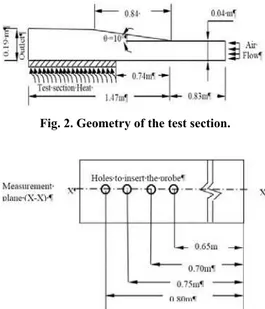
Fig. 2. Geometry of the test section.
Fig. 3. Top view of the test section geometry.
In the present experimental study consideration is
given on the flow characteristics and temperature measurement for turbulent forced convection flow in a rectangular diffuser. The conditions in the experimental work are taken as mixed convective steady turbulent air flow in a bottom heated horizontal rectangular diffuser. The effects of dimensionless parameters such as local Nusselt numbers and Reynolds numbers for this type of flow have been investigated.
2. E
XPERIMENTALS
ETUPA
NDM
EASUREMENTT
ECHNIQUEwhich all the outputs of the thermocouples are connected. The measurement of heat transfer is carried out under isoflux steady state condition. The working fluid in the diffuser is air, supplied by a centrifugal type variable speed blower (Model No: DDEI-00164) fitted with a D.C. motor. A developing channel is formed which is attached with the inlet of the diffuser. The dimension of the developing section is 0.2 × 0.2 × 0.83 m. The velocities of air are measured inside the diffuser using Pitot static tube already calibrated connected with a Pressure Transducer (Range-± 10000 Pa, Air Velocity: 2 to 100 m/s). The probe made of a thyristor is used for measuring temperature of ambient air and instantaneous air temperatures at different heights inside the diffuser.
The working Newtonian fluid is air of density ρair =1.164 kg/m3 , dynamic viscosity µ= 1.983× 10⁻⁵ Pa-s and kinematic viPa-scoPa-sity of air ν= 1.7 × 10⁻⁵ m2 /s at room temperature T1 = 303K and barometric pressure = 101.6 KPa. The average velocity at inlet Uav is taken as 15.308, 16.978, 22.874 m/s (Re=3.594×10⁴, 3.896×10⁴ and 5.371×10⁴ respectively). The velocity distribution curves are obtained at different stations. The equations for the density, velocity, Reynolds numbers, Nusselt numbers, co-efficient of skin friction and the thermal boundary layer of the working fluid flowing through the diffuser are hereby given below:
s m air p
u 2 9.81 / (1)
d
b U air
Re (2)
wall T x b T x dy dt w
x Nu
) ( /
(3)
99 . 0 ) (
,
X b wall
L B wall
T T
T
T (4)
µ / ρ (5)
= , where = / , and u*2 =τwall / ρair (6) T+ = T/ T
b (7) Gr = gβ(Tw –Tin ) d3 /ν2 (8) Ra= gβ(Tw –Tin ) d3 /να (9) Ra* = gβq
con d4/να kair (10) qcon = hav (Tw –Tin ) (11)
3. R
ESULTSA
NDD
ISCUSSIONSValidation Study of Skin Friction
Coefficient:
The experimental results shown in Fig. 4 of turbulent air flow through the asymmetric rectangular diffuser heated at the bottom horizontal wall used in the experiment have been validated
with the published work of Buice et al. (2000) and Lan et al. (2009). The non dimensional value using the ratio of station distances commencing from the inlet section and height of inlet section of the diffuser are presented in the two dimensional co-ordinate system in which X-axis is parallel to the upstream flow and Y- axis is normal to the X-axis. The centre-line velocity at the inlet is 1.14Ub where Ub is 13.44 m/s. The Reynolds number is
airUbd or 3.594 × 10⁴. The length of the settling chamber is 83 cm and the inlet height of the rectangular diffuser is 4 cm, so the ratio of the length of the settling chamber and the height of the inlet section is 20.75 which indicate the persistence of developed flow at the outlet of the diffuser. A uniform and constant heat flux is supplied at the lower horizontal wall 0.74m away from the inlet of the diffuser, the inclination angle of which is kept fixed at 10◦ in conformity with the set up of Buice et al (2000). The study is carried over at an isothermal condition at the temperature of 323K. The variations of coefficient of skin friction at different stations in the diffuser are seen with full agreement of the data provided by Buice et al. (2000) and Lan et al. (2009) which are clear from the Fig. 4. A critical observation of the skin friction profile at the section of S/d10.6, 1000 × Cf = 0.059, -0.13 and -0.13 in respect of experimental, Lan et al. (2009) and Buice et al. (2000) data respectively, which shows a little difference between the experimental value with that of Lan et al. (2009) and Buice et al. (2000) data. At the station S/d= 26.25, 1000 × Cf = 0.05, 0.13 and -0.13 in respect of experimental, Lan et al . (2009) and Buice et al . (2000) data respectively. At the station S/d= 30 and 37 which are at the outlet of the diffuser 1000 × Cf = 0.046, 0.25, 0.84 and 0.1, 0.4,0.337 in respect of experimental, Lan et al. (2009) and Buice et al. (2000) data respectively. These phenomena explore the idea of leaning out the differences between the experimental value and the values given by Lan et al. [2009] and Buice et al. (2000). It is observed that the Skin friction coefficient distribution of present experiment and that of Buice et al. (2000) and Lan et al. (2009) is matching very well.
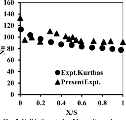
Fig. 5. Validation study of Nusselt number.
Validation Study of Nusselt Number:
The experimental study on Nusselt number distribution has been validated at Reynolds number equal to 3.594 × 10⁴ and 343K.
At the section x/S= 0.2 away from the inlet section of the diffuser Nu=91.955 and 96.77 in respect of experimental and Kurtbas (2008) data; so the observed value is closer the value of Kurtbas (2008) data. At S/X= 0.4, 0.6, 0.8 and 1 away from the inlet section, the present experimental values of Nu become 101.2, 93.1, 91.8 and 91.3 whereas Nu data for Kurtbas (2008) are 96.77, 87.366, 83.452, 80.91 and 77.696 which also explicitly declares the good agreement between the experimental value and the published data of Kurtbas (2008). This corresponds with the other values as well.
Inlet velocities are measured for the calculation of Reynolds numbers which otherwise characterizes the nature of flow at the inlet.
The lower wall of the horizontal diffuser is heated at about 323K and 343K respectively. Measurement has been taken along the mid-stream plane XXto ensure two-dimensional flow. The velocity component at the walls equals to zero for assuming no-slip condition.
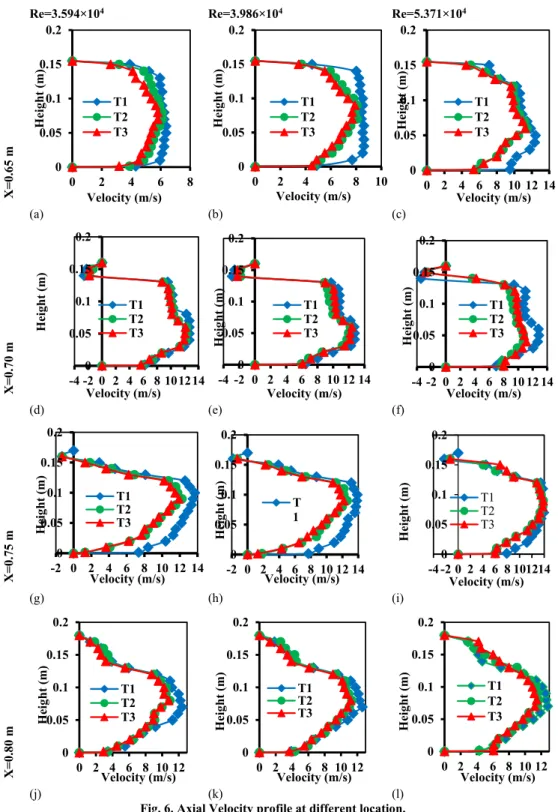
From the Fig. 6(a) to Fig. 6(c), it has been observed that there is no recirculation zone. It has been observed that velocity with the application of heat is lesser than the velocity without heating. In each of the stations the axial velocities with and without the application of heat have been estimated. Fig. 6(d) to Fig. 6(i) illustrates the recirculation zones. Fig. 6(j) to Fig. 6(l) depicts the region of reattachment of flow. Recirculation is about to start from the distance of 0.7 m measured from the inlet section of the diffuser. However recirculation does not originate from this point; it starts little earlier. Similarly it is found that flow reattachment occurs at the distance of 0.8 m away from the inlet. Here also it can be stated that reattachment appears little later. The recirculation bubble length is calculated as 0.1 m and recirculation width is 0.0225 m approximately for
the case of without heating. The strength of recirculation in the case of heating decreases considerably to approximately 30-35 % reduction. Usually recirculation means a zone of low pressure with lower velocity flow reversal zone. As this zone increases, so the main flow gets shortened and the flow velocities are also changing correspondingly. So the stream wise and cross flow velocity change and simultaneously the heat transfer particularly the convective heat transfer rate also changes. This is the effect of the recirculation on the heat transfer phenomena on the opposite wall. Reynolds numbers of the inlet flows are 3.594×10⁴; 3.986×10⁴ and 5.371×10⁴ respectively, the calculation being based on the inlet duct height and mean axial velocity. As the Reynolds number increases axial flow velocity also increases causing higher rate of heat transfer by convection. From the figures 7 (a) and (b), it is observed that coefficient of skin friction on the lower wall is decreasing faster than the upper wall. With the addition of heat, the coefficient of skin friction increases. At the recirculation zones the values of coefficient of skin friction are negative. The region of negative values of coefficient of skin friction agrees with the results under the zones of negative velocity which affirms the recirculation region. The coefficient of skin friction is estimated based on the mean velocity of air in the axial direction. The present experimental data of coefficient of skin friction over the zone of interest are correlated as the function of the Reynolds number and these correlations are valid in the Reynolds number 3.594×10⁴, 3.986×10⁴ and 5.371×10⁴ respectively. The correlations are obtained as seen from Fig. 8(a), Fig. 8(b) and table 1.
Table 2 shows the variations of wall shear stress and skin coefficient data using log law at the wall. A minor deviation of Skin friction coefficient is occurred considering log law at the wall comparing the data with velocity gradient. Table 3 shows the dt+ /dy+ data for evaluating Nusselt number considering logarithmic value of the normalized height and normalized temperature data at certain location (using thermal law at the wall).
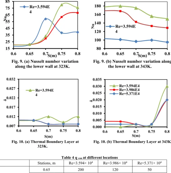
Figure 9(a) and Fig. 9(b) narrate the variation of Nusselt number with the station distance measured along the axial direction in the mid-stream plane
X
X . At the thermally developing region of flow which starts from the distance 0.74 m away from the inlet section of the diffuser Nusselt number increases showing greater amount of heat transfer by convection and thereafter it becomes nearly constant at the downstream of the diffuser. This is because the thermal boundary layer is simultaneously developing along with the velocity boundary layer. When the thermal Boundary Layer gets fully developed then the temperature gradient becomes zero. So the Nusselt number practically becomes constant. Towards the downstream side of the diffuser the difference between the surface temperature and ambient temperature becomes larger causing Nusselt number to decrease.
0
20
40
60
80
100
120
140
160
0
0.2
0.4
0.6
0.8
1
Nu
X/S
Re=3.594×10⁴ Re=3.986×10⁴ Re=5.371×10⁴
X=
0
.65
m
(a) (b) (c)
X=0.70 m
(d) (e) (f)
X=0
.75
m
(g) (h) (i)
X=0
.80
m
(j) (k) (l)
Fig. 6. Axial Velocity profile at different location.
Table 1 Correlation between
C
f and ReThermal Condition
C
fat Lower wall
C
fat Upper wall
Without heating
0.631Re
-0.711.504Re
-0.91K
323
0.191Re
-0.592.14Re
-0.94K
343
0.006Re
-0.2710.92Re
-1.090 0.05 0.1 0.15 0.2
0 2 4 6 8
Hei g ht (m) Velocity (m/s) T1 T2 T3 0 0.05 0.1 0.15 0.2
0 2 4 6 8 10
Hei g ht (m) Velocity (m/s) T1 T2 T3 0 0.05 0.1 0.15 0.2
0 2 4 6 8 10 12 14
Height (m) Velocity (m/s) T1 T2 T3 0 0.05 0.1 0.15 0.2
-4 -2 0 2 4 6 8 101214
Hei g ht (m) Velocity (m/s) T1 T2 T3 0 0.05 0.1 0.15 0.2
-4 -2 0 2 4 6 8 10 12 14
Height (m) Velocity (m/s) T1 T2 T3 0 0.05 0.1 0.15 0.2
-4 -2 0 2 4 6 8 10 12 14
Hei g ht (m) Velocity (m/s) T1 T2 T3 0 0.05 0.1 0.15 0.2
-2 0 2 4 6 8 10 12 14
Height (m) Velocity (m/s) T1 T2 T3 0 0.05 0.1 0.15 0.2
-2 0 2 4 6 8 10 12 14
Height (m) Velocity (m/s) T 1 0 0.05 0.1 0.15 0.2
-4 -2 0 2 4 6 8 101214
Hei g ht (m) Velocity (m/s) T1 T2 T3 0 0.05 0.1 0.15 0.2
0 2 4 6 8 10 12
Height (m) Velocity (m/s) T1 T2 T3 0 0.05 0.1 0.15 0.2
0 2 4 6 8 10 12
Hei g ht (m) Velocity (m/s) T1 T2 T3 0 0.05 0.1 0.15 0.2
0 2 4 6 8 10 12
Cf Lower Wall Cf Upper Wall
Re
=3
.59
4
×1
0
4
(a) (b)
Fig. 7. Coefficient of Skin Friction.
Lower Wall Upper Wall
(a) (b)
Fig. 8. Variation of Coefficient of skin friction with Reynolds Number.
Table 2 τwall and Cf using log law at the wall C f (Lower
wall)
τwall (Lower
wall) Stations, m τwall (Upper wall) C f (Upper wall)
Re=3.594× 10⁴ 6.87× 10⁻⁴ 9.36× 10⁻²
S=0.65 5.72 × 10⁻² 4.19× 10⁻⁴ S=0.7& 0.75 -3.41× 10⁻² -2.50× 10⁻⁴ S=0.8 3.41× 10⁻² 2.50× 10⁻⁴
Re=3.986× 10⁴ 5.16× 10⁻⁴ 8.65× 10⁻²
S=0.65 5.74× 10⁻² 3.42× 10⁻⁴ S=0.7& 0.75 -3.14× 10⁻² -1.87× 10⁻⁴ S=0.8 3.14× 10⁻² 1.87× 10⁻⁴
Re=5.371× 10⁴ 2.31× 10⁻⁴ 7.04× 10⁻²
S=0.65 4.23× 10⁻² 1.39× 10⁻⁴ S=0.7& 0.75 -2.51× 10⁻² -8.23× 10⁻⁴ S=0.8 2.51× 10⁻² 8.24× 10⁻⁴
Table 3 dT+ /dY+ using log law at the wall
Stations, m Re=3.594× 10⁴ Re=3.986× 10⁴ Re=5.371× 10⁴
323K 0.65 0.545031 0.515962 0.487445
0.7 0.562358 0.531349 0.502414
0.75 0.580587 0.541385 0.505873
0.8 0.577511 0.538524 0.507023
343K 0.65 0.544071 0.515121 0.487285
0.7 0.54552 0.51511 0.487141
0.75 0.545973 0.515263 0.48804
0.8 0.545823 0.518063 0.490763
0.0000 0.0002 0.0004 0.0006 0.0008
0.6 0.65 0.7 0.75 0.8
Cf
S(m) 343K 323K without heat
-0.0001 0.0000 0.0001 0.0002 0.0003 0.0004 0.0005 0.0006
0.6 0.65 0.7 0.75 0.8
Cf
S(m) 343K 323K without heat
3C
f= 0.631Re -0.71 2C
f= 0.191Re -0.59 1C
f= 0.006Re-0.27
0.00025 0.00030 0.00035 0.00040 0.00045
35,000 40,000 45,000 50,000 55,000
Cf
Re
without heat
323K
343K
1
1
1
2
3
3Cf= 1.504Re -0.91 2C
f= 2.148Re -0.94 1C
f= 10.92Re -1.09
0.00006 0.00007 0.00008 0.00009 0.00010 0.00011 0.00012
35,000 40,000 45,000 50,000 55,000
Cf
Re
without heat
323K
Fig. 9. (a) Nusselt number variation
along the lower wall at 323K.
Fig. 9. (b)
Nusselt number variation along
the lower wall at 343K.
Fig. 10. (a) Thermal Boundary Layer at 323K.
Fig. 10. (b) Thermal Boundary Layer at 343K.
Table 4 q con at different locations
Stations, m Re=3.594× 10⁴ Re=3.986× 10⁴ Re=5.371× 10⁴
323K
0.65 200 120 50 0.70 900 500 300 0.75 2000 2000 2000 0.80 2000 2000 2000
343K
0.65 500 300 100 0.70 1200 1200 500 0.75 4000 4000 4000 0.80 4000 4000 4000
From Fig. 11 it is observed that with the increase of Reynolds number average Nusselt number increases due to the large forced convection of heat flow and turbulence of air. The average Nusselt number is estimated by integrating the local Nusselt numbers. From the experimental observation the correlations between average Nusselt numbers and Reynolds numbers for the air flow inside a diffuser are obtained at the temperatures 323 K and 343 K
as per the table 5. Table 4 shows the variation of average convection heat flux transferred to the air considering hav = 100 W/m2K .
The above mentioned correlations are valid for Reynolds numbers 3.594×10⁴, 3.986×10⁴ and 5.371×10⁴ respectively. Figs. 10(a) and 10(b)
represent the thermal boundary layer profiles with respect to the axial distances at the temperatures
K
323 and 343K respectively. Thermal Boundary layer fluctuates more as the heated plate is approached. Fluctuation increases with the increase of temperature. As Reynolds number increases the thickness of Thermal Boundary Layer decreases. At the outlet of the diffuser the thickness becomes nearly constant.
From the graphical interpretation of Fig. 6(d) and Fig. 6 (e) it has been noticed that the velocity with heating is little more than without heating. This discrepancy is not abrupt since the recirculation has been found to be preceded little earlier for the case of without heating. So it is expected that the
15
25
35
45
55
65
75
85
0.6
0.65
0.7
0.75
0.8
Nu
S(m)
Re=3.594E
4
80
100
120
140
160
180
0.6
0.65
0.7
0.75
0.8
Nu
S(m)
Re=3.594E
4
0.007 0.012 0.017 0.022 0.027 0.032
0.6 0.65 0.7 0.75 0.8
δ
S(m) Re=3.594E 4
0.000 0.005 0.010 0.015 0.020 0.025 0.030 0.035
0.6 0.65 0.7 0.75 0.8
δ
recirculation followed by the flow separation for the case of without heating will be terminating or the reattachment point will be shifted further downstream for the case of with heating.
Fig. 11 Variation of Nusselt number with Reynolds number.
Table 5 Correlation between Nusselt Number with Re
Table 6 Gr and Ra at different temperatures
323K 343K
Gr 1.44 × 10⁵ 2.88 × 10⁵
Ra 20928 41856
Ra* 3.17 × 106 6.34× 10⁶
A major finding of the research work is whether the recirculation increases, remains constant or decreases for bottom wall heating. The present researcher found that the recirculation decreases with the increase of temperatures. This can be attributed due to the reason that the heating results in increase of viscosity and lowers the flow velocity. The augmented viscous effects are dominant particularly near the wall and this is responsible for this phenomenon. A higher velocity is quite capable of withstanding the adverse pressure gradient further downstream rather than a lower flow velocity, which is prone to separate due to inability to counter an adverse pressure gradient earlier. The ultimate consequence is the reduction of the recirculation bubble strength for the case of application of heat to the flow from the lower wall.
4.
D
ISCUSSIONO
NG
RASHOFN
UMBERA
NDR
AYLEIGHN
UMBERBuoyancy and viscous forces in the fluid influences the transition in a free convection boundary layer. Grashof number is calculated as 2.88 × 10⁵ whereas Rayleigh number is equal to 20928 and 41856 considering the bottom wall temperature as 323K
and 343K. When uniform heat flux is considered Rayleigh number changes to 3.17 × 10⁶ and 6.34 × 10⁶ at the same conditions. Here thermal diffusivity
=1.17 × 10⁻⁴ m2 /s , β= 3.315 × 10⁻³ (1/K) and k air = 0.0264 W/mK.
A greater value of Rayleigh number significantly describes the heat transferred by the convection method from the bottom most wall to the upper surface and consequently, the flow becomes turbulent.
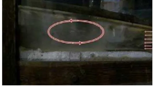
Fig. 12. Visualisation Study.
5.
V
ISUALISATIONS
TUDYA high resolution camera is used for taking the photograph and white smoke is used as the indicator delivered from the inlet section of the diffuser. From the visualization study indicated by the red marking it has been seen that recirculation starts on the upper inclined wallat the upstream section of the diffuser and gets diminished at the downstream portion. The size of the recirculation bubble is nearly same as determined by the experimental process. With the application of heat the recirculation regime becomes somewhat decreased.
6.
C
ONCLUSIONS Forced convective heat transfer inside a two dimensional rectangular asymmetric (10o axial inclination) with bottom wall horizontal diffuser is investigated experimentally. The experiment has been carried out under a uniform wall heat flux within of Reynolds numbers 3.594×10⁴, 3.986×10⁴ and 5.371×10⁴ and temperatures of 323 K and 343 K respectively.
The recirculation is generating at the upper wall of the diffuser. Before and after the recirculation the velocity profiles are turbulent like distributions.
With the application of heat recirculation strengths reduce appreciably.
With the increase of Reynolds number the value of coefficient of friction increases.
With the increase of Reynolds number, Nusselt number increases exhibiting more enhancement of heat transfer. The Nusselt number is more for higher temperature.
Empirical correlations are established for the Average Nusselt number and coefficient of Thermal
Condition Nusselt Number
323K Nu=0.019Re 0.723
friction with Reynolds number which can be roughly used for the estimation of these quantities.
A
CKNOWLEDGEMENTThe authors express their sincere thanks and gratitude to all who are extending their helping hand by giving valuable suggestions and technical support for this work done at Hydraulics Laboratory, Mechanical Engineering Department, Jadavpur University, Kolkata (India).
The author2 also acknowledges the financial support of UGC (RGNF), Govt. of India.
R
EFERENCESAbe, H., H. Kawamura and Y. Matsuo (2004). Surface heat-flux fluctuations in a turbulent channel flow up to Reτ = 1020 with Pr = 0.025 and 0.71. Int. J. Heat and Fluid Flow 25, 404-419.
Bejan, A. (1993). Heat Transfer, John Wiley and Sons, New York.
Bhattacharjee, S., R. Debnath, A. Mandal, D. Roy and S. Majumder (2010). Experimental investigation of Recirculatory turbulent flow past twin obstructions of different heights placed at different stations of a Rectangular diffuser. In Proceedings of the 37th National and 4th International Conference on Fluid Mechanics and Fluid Power, IIT Madras, Chennai, India, EM – 05, 1-8.
Bhattacharjee, S., R. Debnath, D. Roy and S. Majumder (2011). An experimental study on turbulent air flow through a two-dimensional rectangular diffuser. IE (I) Journal-MC 92, 3-7. Buice, C. U. and J. K. Eaton (2000). Experimental
Investigation of Flow through an Asymmetric Plane Diffuser. Journal of Fluid Engineering 122, 433-435.
Chang, M. Y. and T. F. Lin (1998). Experimental study of aspect ratio effects on longitudinal vortex flow in mixed convection of air in a horizontal rectangular duct. Int. J. Mass Transfer 41, 719-733.
Cherry, E. M., G. Iaccarino, C. J. Elkins and J. K. Eaton (2006). Separated flow in a three dimensional diffuser: preliminary validation. Annual Research Briefs, Center for Turbulence Research 31-40.
Chiu, K. C., J. Quazzani and F. Rosenberger (1987). Mixed convection between horizontal plates-II. Fully developed flow. Int. J. Heat Mass Transfer 30, 1655-1662.
Devia, F. and G. Tanda (2000). Investigation of natural convection heat transfer from a horizontal isothermal plate by Schlieren tomography. Int. J. Heat Technology 18, 41-46.
Durbin, P. (1995). Separated Flow Computations
with the k-ε-v2 Model. AIAA Journal 33, 659-664.
Friedrich, M. K. and D. Angirasa (2001). Interaction between stable thermal stratification and convection under a heated horizontal surface facing downwards. Int. J. Non-Linear Mech. 36, 719-729.
Huang, C. C. and T. F. Lin (1996). Numerical simulation of transitional aiding mixed convective air flow in a bottom heated inclined rectangular duct. Int. J. Heat Transfer 39, 1697-1710.
Huang, C. C. and T. F. Lin (1995). Vortex flow and thermal characteristics in mixed convection of air in a horizontal rectangular duct: effects of the Reynolds and Grashof numbers. Int. J. Heat Mass Transfer 38(1), 661-1674.
Hwang, G. J. and C. L. Liu (1976). An experimental study of convective instability in the thermal entrance region of a horizontal parallel-plate channel heated from below. Canadian Journal of Chemical Engineering 54, 521-525.
Iaccarino, G. (2001). Prediction of a turbulent separated flow using commercial CFD codes. Journal of Fluids Engineering 123, 819-828. Incropera, F. P., D. P. Dewitt, T. Bergman and A.
Lavine (2007). Fundamentals of Heat and Mass Transfer, 6th Ed., Wiley.
Incropera, F. P. (1988). Convective heat transfer in electronic equipment cooling. J. Heat Transfer 110, 1097-1111.
Incropera, F. P. and D. G. Osborne (1985). Experimental study of mixed convection heat transfer for transitional and turbulent flow between horizontal, parallel plates. Int. J. Heat Mass Transfer 28, 1337-1344.
Incropera, F. P. and D. G. Osborne (1985). Laminar, mixed convection heat transfer for flow between horizontal parallel plates with asymmetric heating. Int. J. Heat Mass Transfer 28, 207-217. Incropera, F. P., A. L. Knox and. J. R. Maughan
(1987). Mixed convection flow and heat transfer in the entry region of a horizontal rectangular duct. J. Heat Transfer 109, 434-439.
Kamotani, Y., S. Ostrach and H. Miao (1979). Convective heat transfer augmentation in thermal entrance regions by means of thermal instability. Journal of Heat Transfer 101, 222-226.
Kays, W. M. and A. L. London (1984). Compact Heat Exchangers, 3rd. Ed., McGraw-Hill New York.
Kong, H., H. Choi and J. S. Lee (2000). Direct numerical simulation of turbulent thermal boundary layers. Physics of Fluids 12, 2555-2568.
a high spatial resolution. Int. J. Heat and Fluid Flow 30, 514-524.
Kurtbas, I. (2008). The effect of different inlet conditions of air in a rectangular channel on convection heat transfer: Turbulence flow. Expt. Thermal and fluid Science 33, 140-152. Lan, H., B. F. Armaly and J. A. Drallmeier (2009).
Turbulent Forced Convection in a Plane Asymmetric Diffuser: Effect of Diffuser Angle. J. Heat Transfer, Trans. ASME 131
Lee, J., S. Y. Jung, H. I. Sung and T. A. Zaki (2013). Effect of wall heating on turbulent boundary layers with temperature-dependent viscosity. J. Fluid Mech. 726, 196-225.
Lewins, J. D. (2004). Comparative solutions to the integral approximate thermal boundary layer equations for a flat plate. Int. J. Mechanical Engineering Education 32, 315-344.
Li, Q., P. Schlatter, L. Brandt and D. S. Hennigson (2013). DNS of a spatially developing turbulent boundary layer with passive scalar transport. Int. J.Heat and Fluid Flow 30, 916-929.
Lin, W. L. and T. F. Lin (1996). Experimental study of unstable mixed convection of air in a bottom heated horizontal rectangular duct. Int. J. Heat Mass Transfer 39, 1649-1663.
Lin, W. L., Y. T. Ker and T. F. Lin (1996). Experimental observation and conjugated heat transfer analysis of vortex flow development in mixed convection of air in a horizontal rectangular duct. Int. J. Heat and Mass Transfer 39, 3667-3683.
Ma, L. D., Z. Y. Li and W. Q. Tao (2007). Direct numerical simulation of turbulent flow and heat transfer in a square duct with natural convection. Heat Mass Transfer 44, 229-250.
Majumder, S., D. Roy, S. Bhattacharjee and R. Debnath (2014). Experimental investigation of the turbulent fluid flow through a rectangular diffuser using two equal baffles. J. Inst. Eng. India Ser. C 95, 19-23.
Maughan, J. R. and E. P, Incropera (1990). Fully developed mixed convection in a horizontal channel heated uniformly from above and below. Numerical Heat Transfer 17, 417-430.
Maughan, J. R. and F. P. Incropera (1987). Experiments on mixed convection heat transfer for air flow in a horizontal and inclined channel. Int. J. Heat Transfer 30, 1307-1318.
Morcos, S. M., M. M. Hilal, M. M. Kamel and M. S. Soliman (1986). Experimental investigation of mixed laminar convection in the entrance region of inclined rectangular channels. Int. J. Heat Mass Transfer 108, 574-579.
Mori, Y. and Y. Uchida (1996). Forced convective heat transfer between horizontal flat plates. Int. Journal of Heat & Mass Transfer 9, 803-817. Morinishi, Y., S. Tamano and E. Nakamura (2007).
New scaling of turbulence statistics for incompressible thermal channel flow with different total heat flux gradients. International J. of Heat and Mass Transfer 50, 1781-1789. Nicoud, F. C. (1998). Numerical Study of a Channel
Flow with Variable Properties. Center for turbulent Research. Annual Research Briefs 289-309.
Obi, S., K. Aoki and S. Masuda (1993). Experimental and Computational Study of Separating Flow in an Asymmetric Plane Diffuser. 9th Symposium on Turbulent Shear Flows, Kyoto, Japan, 1-4.
Ostrach, S. and Y. Kamotani (1975). Heat transfer augmentation in laminar fully developed flow by means of heating from below. Journal of Heat Transfer 97, 220-225.
Ostrach, S. and Y. Kamotani (1976). Effect of thermal instability of thermally developing channel flow. Journal of Heat Transfer 98, 62-66.
Sekimoto, A., G. Kawahara, M. Sekiyama and A. Pinelli (2011). Turbulence and buoyancy driven secondary flow in a horizontal square duct heated from below. Physics of Fluids 23.
Serra, S., A. Toutant and F. Bataille (2012). Thermal Large eddy simulation in very simplified geometry of a solar receiver. Heat Transfer Engineering 33, 505-524.
Serra, S., A. Toutant, F. Bataille and Y. Zhou (2012). Turbulent kinetic energy spectrum in very anisothermal flows. Physics Letters, A 376, 3177-3184.
Serra, S., A. Toutant, F. Bataille and Y. Zhou (2012). High-temperature gradient effect on a turbulent channel flow using thermal large-Eddy simulation in physical and spectral spaces. J. of Turbulence 13, 1-25.
Shuja, S. Z. and M. A. Habib (1996). Fluid flow and heat transfer characteristics in axisymmetric annular diffusers. Computers & Fluids 25, 133-150.
Tiselj, I., E. Pogrebnyak, C. Li, A. Mosyak and G. Hetsroni (2001). Effect of wall boundary condition on scalar transfer in a fully developed turbulent flume. Physics of Fluids 13, 1028-1039.
Toutant, A. and F. Bataille (2013). Turbulence statistics in a fully developed channel flow submitted to a high temperature gradient. International Journal of Thermal Sciences 74, 104-118.
Wu, X. and P. Moin (2010). Transitional and turbulent boundary layer with heat transfer. Physics of Fluids 22.