I. K. Adegun and
F. L. Bello-Ochende
Mechanical Engineering Department Faculty of Engineering and Technology University of Ilorin, Ilorin, Nigeria [email protected]Mixed Convective and Radiative Heat
Transfer in an Inclined Rotating
Rectangular Duct with a Centered
Circular Tube
A numerical study of steady state laminar forced and free convective and radiative heat transfer in an inclined rotating rectangular duct with a centered circular tube is reported for an hydrodynamically fully developed flow. The two heat transfer mechanisms of convection and radiation are treated independently and simultaneously. The coupled equations of momentum and energy transports are solved using Gauss-Seidel iteration technique subject to given boundary constraints. A thermal boundary condition of uniform wall temperature in the flow direction is considered. A special discritization method is employed to solve the problem associated with near boundary grid points. Results for mean and total mean Nusselt numbers for various values of Reynolds number ,Re; Rayleigh number , Ra ; Geometric ratio ,rg ; Aspect ratio, rA ; Radiation-Conduction parameter ,
.
; Optical thickness,ϑ
; Rotational Reynolds number ,Ro and Emissivity, ε ; are presented. For the range of parameters considered, results show that radiation and rotation enhance heat transfer. It is also indicated in the results that heat transfer from the surface of the circle exceeds that of the rectangle. Optimum heat transfer and fluid bulk temperature are attained when the duct is vertically positioned. The Parameter ranges of 0.2#
rg#
0.84, 0#
PeRa#
7.3 x 10⁵ and rg <rA#
1 demarcate the extent of the validity of the numerical solution.Keywords: Mixed Convective, Radiative , Heat Transfer , Inclined, Rotating, Rectangular
Duct, Centered, Circular Tube
Introduction
Various heat transfer mechanisms and geometries have been studied by some engineers and scientists purposely to augment heat transfer in heat exchangers and some other heat transfer equipment. Dong et al [1] employed the geometry combination of a square duct with a centered circular core for the design of an oven for heat treatment of ceramic and metallic products. They studied a situation where the central core is solid. Thermal radiation and laminar forced convection in the entrance region of a pipe with axial conduction and radiation were considered by Yang and Ebadian [2]. Combined natural convection- conduction and radiation heat transfer in discretely open cavity was studied by Dehgham et al [3] . Siegel [4] also analyzed the effect of buoyancy on heat transfer in a rotating tube. The cooling of rotating devices that are parallel or perpendicular to the axis of rotation have been extensively reviewed and discussed in the book of Morris [5]. A numerical study of natural convection in horizontal elliptic cylinder was studied by Bello-Ochende [6]. He developed a recurrence relation to generate successively decreasing grid sizes between any two neighbouring nodes. A perturbation analysis of combined free and forced laminar convection in a tilted elliptic cylinder was carried out by Bello-Ochende and Adegun [7]. Bello-Bello-Ochende and Adegun [8] also worked on combined convective and radiative heat transfer in a tilted, rotating, uniformly heated square duct with a centered circular cylinder. The work under investigation is to augment heat transfer in heat exchangers using geometric combination of a rectangular duct and a circular core . The working fluid flows in between the inner surface of the rectangular duct and outer surface of the circular cylinder.1
Paper accepted August, 2004. Technical Editor: Atila P. Silva Freire.
Nomenclature
b = radius
A = Major diameter A* = Cross-sectional area
Cx , Cy = Coefficients in equations (13)
Cc ,Cr = Coefficients in equations (16)
d = Hydraulic diameter (4A*/ P* ) g = Acceleration due to gravity (m/s2 ) rg = Geometric ratio (A/L)
Gr = Grashot number h = Heat transfer coefficient
H = Height of the rectangular cross section K = Thermal conductivity of the working fluid L = Length of the rectangular cross section n = Outward normal on the wall
N = Number of Divisions in zones B1 and B2 N2 = Number of Divisions in zones A and C Nuc = Mean Nusselt number for the circular surface
Nur = Mean Nusselt number for the rectangular duct
NuT = Total mean Nusselt number
NuLc = Local Nusselt number on the circular surface
NuLr = Local Nusselt number for the rectangular duct
P* = Wetted perimeter
P1 = The small pressure variation governing the flow distribution in the cross stream plane
P11 = Average pressure over the duct cross section Pr = Prandtl number , < / ∀
Re = Modified Reynolds number based on hydraulic diameter, d Ro = Rotational Reynolds number, Σd2/<
T = Dimensional fluid temperature Tw = Local wall temperature
Vx = Dimensional velocity in x-direction
U = Normalized velocity in 0-direction Vy = Dimensional velocity in y-direction
Vz = Dimensional velocity in z-direction
W = Normalized velocity in ∋-direction X = Horizontal coordinate
Y = Vertical coordinate
Z = Coordinate in the direction of flow (axial direction)
Greek Symbols
∀ = Thermal diffusivity (m2/s) ∃ = Coefficient of thermal expansion
∋ = Dimension less coordinate in axial direction . = Radiation conduction parameter
0 = Dimension less horizontal coordinate < = Kinematic viscosity of the fluid (m2/s) > = Dimension less vertical coordinate Φ = Stefan Boltzmann constant ( Wm2 / k4) ϑ = Optical thickness
1 = Normalized fluid temperature
Π = Volumetric absorption coefficient ( 1/m) Τ = Angular velocity
Σ = Vorticity , Ρ = Stream function
8 = Inclination to the horizontal γ = Emissivity
(Μ1/ Μn)∗w = Temperature gradient normal to the wall surfaces
Subscripts
b = Bulk c = cicle f = Fluid
Lc = nodal point on the circle
Lr = nodal point on the rectangle
r = rectangle w = wall
Mathematical Formulation of the Problem
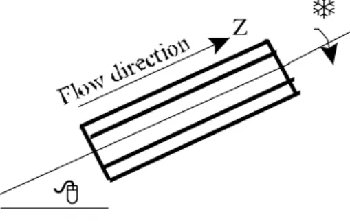
The schematic drawing of the geometry and the cartesian co-ordinate system employed in solving the problem is shown in Fig. 1.
X
Y
V
xV
yV
zFigure 1. The coordinate system and the physical model of the geometry.
Z
Figure 1. (Continued).
The inclined rectangular duct rotates with an angular velocity Τ. H is the height of the rectangular cross-section, L is the width. b is the radius of the circular core. The working fluid is assumed absorbing, emitting and the fluid properties are assumed constant except for density variation with temperature resulting in the secondary flows generated by the buoyancy forces. The axial (z) direction shown in Fig.1 is the predominant direction for the fluid flow. The flow is laminar, and viscous dissipation effects are neglected. Axial conduction and radiation are assumed negligible following Yang and Ebadian [2] for a condition that Peϑ/Η >10.
Governing Equations
Following the assumptions made, the governing equations are:
Continuity Equation
0 = ∂ ∂ + ∂ ∂
Y V
X
Vx y . (1)
Momentum Transport Equation
The momentum transport equations in the x- , y- and z- directions are respectively;
( )
x M X P YV V X V
Vx x y x ∂ +
′ ∂ − = ∂ ∂ + ∂
∂ 1
ρ , (2)
( )
y M Y P YV V X V
Vx y y y +
∂ ′ ∂ − = ∂ ∂ + ∂
∂ 1
ρ , (3)
( )
z M Z P Y V V X VVx z y z ∂ +
′′ ∂ − = ∂ ∂ + ∂
∂ 1
ρ , (4)
where
( )
x Vx F( )
x VyM =ν∆2 + +2ω
( )
y Vy F( )
y VxM =ν∆2 − +2ω
( )
z V F( )
z M =ν∆2 z− ,and
Z P Z P
∂ ′ ∂ << ∂
′ ∂
Also,
[
]
[
]
= ) ( = = λ β λ β Sin Cos T -Tw g z F T -Tw g F(y) 0 F(x). (5)
Energy Transport Equation
In the absence of energy sources and viscous energy dissipation, the energy equation for steady flow, with radiation incorporated is;
( )
t E y T x T Z T V Y T V X TVx y z +
∂ ∂ + ∂ ∂ = ∂ ∂ + ∂ ∂ + ∂ ∂ 2 2 2 2
α , (6)
where,
( )
(
T4 T4)
C t E W P W − = ρ σχε .
The boundary conditions applicable to these equations are: (i) At the inlet of the duct ( Z= 0),
Vx = Vy = 0
T = Te;
(ii) On the wall surfaces; Vx = Vy = Vz = 0
T = T w
Normalization Parameters
The variables in the governing equations and boundary conditions are non- dimensionalized by employing the following transformation parameters: ; -V ; U ; d Z ; d Y ; d X η ψ ξ ψ ξ η ∂ ∂ = ∂ ∂ = = Γ = = ; P d -; d BgT Ra ; ; d 2 3 w Γ ρν αν α ν χ τ ∂ ′′ ∂ = = = = 2 4 Re Pr , T T ; K T ; d . Pr dZ Θ d w w = = = Θ χ εσ ς 4 1 . d V W ; d V V ; d V
U x y z
ν ν
ν = =
=
Where d is the hydraulic diameter defined as,
) (
) (
2
4 * 2
b L H b L H P A d π π + + − =
= ∗∗ . (7)
Solution Technique and Evaluation of Heat Transfer
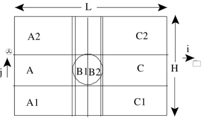
The normalized governing equations are non- linear, non homogeneous and coupled through the temperature, radiation and rotating terms. As a result of these, the equations are amenable to closed-form solution. Finite - difference approximation is found appropriate. A numerical approach involving Gauss-Seidel iteration technique is therefore applied. The entire domain is divided into three zones, namely, A,B and C . Zone A is sub divided into zones A1 and A2, Zone B is sub divided into Zones B1 and B2 . Zone C is also sub divided into C1 and C2 as indicated in Fig. 2.
A2
A1
A
C2
C
C1
B1B2
L
j
H
i
Figure 2. Discretized Domain.
The > - direction, in the circular domain is divided into uniform grid size, ♠> = b / N. Along the same direction, Zones A and C are of uniform grid sizes. In 0 - direction, zones A and C are divided into equal grid sizes while recurrence relations are established for zone B.
Numerical Algorithm
To achieve grid refinement , a recurrence relation is developed in 0 - direction as follows :
(1) For successively increasing grid size ;
2 2 2 2 2 2 ) 1 2 ( 1 ) 1 ( 1 N b i N b i N
I − −
− − = + + η ∆ (8) where,
j = i ; i = 1 , 2 - - - , N.
(2) For successively decreasing grid size ;
2 2 2 2 2 2 ) 1 2 ( ) 1 ( 1 ) ( 1 N b i N N b i N N I − + − − − − = + + η
∆ . (9)
j = N+1- i ; i = 1,2 , - - - , N.
Convergence and Accuracy of Numerical Scheme
Vortex field is first evaluated followed by the stream function. This is followed by the velocity field and lastly by the temperature field. A first approximation for the interior values are evaluated by introducing the initial guess values. The procedures are repeated until convergence is attained subject to the following criterion;
4 1
10 ,
, −
+i j− mi j≤
m γ
γ . (10)
Evaluation of Heat Transfer
The peripheral heat transfer is defined through the conduction referenced Nusselt number as;
Local Nusselt number on the Rectangular duct
The peripheral local Nusselt number on the wall of the rectangular duct is computed from;
(
)
( )) (
1 1
r L w b r
L I
n Nu
∂ ∂ −
= Θ
Θ . (11)
MeanNusselt number on the Rectangular Wall
The mean Nusselt number on the wall of the rectangular duct is obtained as,
S s R
r L
r
R NU NU
∑
= 1 ) (
, (12)
where, Lr =1,2,- - -,Rs and Rs is the total number of nodal points on
the rectangular wall.
Local Peripheral Nusselt Number on the Circular Duct
The peripheral local Nusselt number on the circular duct is computed from;
The coefficients C x and C y are derived from the equation of an
ellipse as;
2 2 2
2 ; η ξ
ξ ξ
η η
+ = +
= y
x C
C . (14)
Mean Nusselt number on the Circular duct
The mean Nusselt number on the circular surface is,
) (
1 ) (
c C L
c
N NU NU
∑
= , (15)
where, Lc = 1,2 , ----, Nc ; Nc is the total number of nodal points on the circular boundary .
Total Mean Nusselt Number
The total mean Nusselt number , NuT is a measure of the
average heat transfer over the internal surface of the rectangular duct and the outer surface of the circular configuration. It is computed from the following equation,
r r C C
T C Nu C Nu
Nu = + , (16)
where Cc Nuc is a measure of average heat transfer from the outer
surface of the circular core while Cr Nur corresponds to heat transfer
from of the internal surface of the rectangular duct. Cc and Cr are
the perimetric ratios for the heat transfer and are defined as ,
b H L
b
CC= +π +π . (17)
b H L
H L Cr + +π
+
= . (18)
Discussion of Results
Results are presented for the following ranges of parameters: 50#Re#2000
0#Ra#104
0#Ro#6 x 10² 0#ϑ#5 0#Η#5 0#γ#1 0#e#1 0.2# rg <1
rg < rA # 1
Figure 3. Variation of total heat transfer with Reynolds number.
Figure 4. Influence of Reynolds number on friction coefficient.
Fig.3 compares the total mean Nusselt number by the two heat transfer mechanisms and for a range of Reynolds numbers. It is noticed that for the pure convection, total mean Nusselt number increases with Reynolds number. For combined heat transfer mechanism, Nusselt number reduces monotonically with increasing Reynolds number. The graph shows that the radiative component of heat transfer is high at low Reynolds number compared to high Reynolds number flow regime. Effect of Reynolds number on friction is highlighted in Fig. 4. It shows that as the Reynolds number increases, the friction coefficient reduces until when Re . 1200. Above this value, the effect of Reynolds number on friction
Nu
b C C
LC x w lc y w LC
( ) )[ ( ) ( )] ( )
1
1−Θ + 13
Θ Θ
∂
coefficient becomes insignificant and assume a fairly constant value. The figure also depicts an inverse proportionality between friction factor and the Reynolds number. Thorough inspection of Figs. (3&4) gives an upper critical Reynolds number of Re . 1200 above which friction coefficient becomes invariant and dNu/d Re becomes negligible.
Figure 5. Variation of total mean Nusselt number with Rayleigh number
Fig.5 presents the variation of total mean Nusselt number with Rayleigh number, Ra . It is observed from the figure that the heat transfer between a parameter range of 0#Ra#400 is fluctuating and therefore not stable . A lower range of 400 < Ra#4000 and upper range of 5000#Ra#10000 are noticed for increase of total mean Nusselt number with increasing Rayleigh number. These ranges correspond to a laminar flow regime. Further inspection of Fig.5 shows an upper critical Rayleigh number, Ra=104 at which optimum heat transfer is attained and a lower critical Rayleigh number , Ra=400 below which convection is not vigorous enough to dominate the heat transfer process. The result of transition from conduction to convection, as indicated in the figure , is a fall in heat transfer coefficient.
Figure 6. Effects of rotation on heat transfer.
Variation of total mean Nusselt number with rotational Reynolds number is indicated in Fig. 6. It is observed from the figure that rotation enhances heat transfer.
Figure 7. Effect of rotational Reynolds number on bulk temperature.
Figure 7 shows the graph of bulk temperature versus rotational Reynolds number for a range of 0#Ro#600. The figure reveals that
the optimum value of bulk temperature is attained when Ro.140 and
the corresponding value is 1111b.0.97641 1111w.
Figure 8. Graph of mean axial velocity versus rotational Reynolds number.
Figure 10. Effect of geometric ratio on total mean Nusselt number.
Effects of rotation on axial flow is obtained in Fig. 8. Figs. 9 and 10 are the graphs of mean Nusselt number for various values of geometric ratio . For the range of 0.2# rg <0.6, the heat transfer by
the rectangular surface increases with increasing geometry ratio while that of circular tube reduces. Above rg = 0.60, the mean
Nusselt number for the two surfaces increase monotonically with geometric ratio. Towards the point of contact of the rectangular and the circular ducts, NuC. NuT.
Figure 11. Variation of total heat transfer with angle of inclination.
Figure 11 established the effects of duct orientation on heat transfer, the graph shows that the optimum heat transfer is attained when the duct is vertically positioned.
Figure 12. Effects of optical thickness, radiation-conduction parameter on heat transfer.
Table 1. Comparism of fr.Re for a square duct with centered circular tube.
S/No. Geometric
Ratio
Fr.Re Present Study
Fr.Re Dong et al. [ 1,2 ]
1 .2 98.59 91.01
2 .3 93.62 ..
3 .4 88.25 ..
4 .5 82.92 87.53
5 .6 78.13 ..
6 .7 74.97 ..
7 .8 76.86 75.76
8 .9 104.49 ..
Table 2. Effects of aspect ratio on heat transfer.
Aspect ratio( RH) rg = 0.5
Total Mean Nusselt Number ( NuT)
1.0 7.136
0.90 9.016
0.80 11.811
0.70 15.628
0.60 22.916
Figure 12 shows the influence of optical thickness and radiation conduction parameter on total mean Nusselt number while the hydrodynamic properties ( fr.Re ) of the fluid flow for various geometric ratios are presented in Table 1. Table 2 is the effect of aspect ratio on the heat transfer.
Concluding Remarks
It is obtained from the results presented that :
1. optimum values of heat transfer and fluid bulk temperature are attained when geometric ratio is 0.84 .
2. effects of radiation is only significant for low values of Reynolds number .
3. Parameter ranges of rg#rA # 0.84 and 0#PeRa# 7.3x10⁵
demarcate the range of validity of the governing equations. 4. the two surfaces when combined together transfer more heat
than when considered separately.
References
Z. F. Dong, M.A. Ebadian and E. Bigzadeh, (1993),Convective -Radiative Heat Transfer in a Square Duct with a Centered Circular Core, International Journal of Heat and Fluid Flow, Vol. 14 , No. 1, PP. 68-75.
G. Yang and M .A . Ebadian, (1991), Thermal Radiation and Laminar Forced Convection in the Entrance of a Pipe With Axial Conduction and Radiation, Int . J. Heat Fluid Flow , Vol.12, No. 3 , PP. 202-209.
A.A. Dehghan and M. Behnia, (1996), Combined Natural Convection – Conduction and Radiation Heat Transfer in a Discretely Heated Open Cavity , Journal of Heat Transfer, Vol. 118, PP.56-64.
R. Siegel, (1985), Analysis of Buoyancy Effect on Fully Developed Laminar Heat Transfer in a Rotating Tube, Journal of Heat Transfer , Vol. 107 , PP. 338-344.
W.D. Morris, (1981), Heat Transfer and Heat Flow in Rotating Coolant Channels, Research Study Press, John Wiley and Sons.
F.L. Bello-Ochende, (1985), A Numerical Study of Natural Convection in Horizontal Elliptic Cylinders, Revista Brasileira de Ciências Mecânicas, Vol. Vii, No.3, PP.185-207.
F.L. Bello-Ochende and I.K. Adegun, (1993). A perturbation Analysis of Combined Free and Forced Laminar Convection in Tilted Elliptic Cylinders, The 6th International Symposium on Transport Phenomena in
Thermal Engineering, Seoul, Vol. iii, PP.121-125.
Heated Square Duct With a Centered Circular Cylinder, International Journal of Heat and Technology, Vol. 20, No.1,PP.21-30.
M. P. Dyko, K. Vafai and A.K. Mojtabi, (1995), A Numerical and Experimental Investigation of Stability of Natural Flow within a Horizontal Annulus Journal of Fluid Mechanics, Vol. 38, PP. 27-62.
K.C. Cheng and Ligiu Wang, (1993). The Effects of Coriolis and Centrifugal Forces on Transition to Turbulence in a Rotating Curved Rectangular Channel, The 6th International Symposium on Transport