www.ocean-sci.net/6/615/2010/ doi:10.5194/os-6-615-2010
© Author(s) 2010. CC Attribution 3.0 License.
Ocean Science
Technical Note: A low cost unmanned aerial vehicle
for ship based science missions
E. Waugh and M. Mowlem
National Oceanography Centre, Southampton, SO14 3ZH, UK
Received: 5 March 2010 – Published in Ocean Sci. Discuss.: 30 March 2010 Revised: 5 June 2010 – Accepted: 14 June 2010 – Published: 1 July 2010
Abstract.A low-cost Unmanned Aerial Vehicle is compared with those already available and the motivation for its devel-opment is established. It is targeted at ship-based science missions and potential applications are described including a specific science case to measure white capping in the deep ocean. The current vehicle includes a range of more than 1000 Km, carrying a payload of 2 Kg and it can be launched and recovered from a coastal research vessel. The vehicle has flown successfully in Force 4 gusting Force 6–7 wind condi-tions, an important requirement for operation at sea. Data analysis is performed on images captured by the vehicle to provide a measurement of wave period and white capping fraction. The next stage of the project is to develop a suitable payload and perform a demonstration science mission.
1 Introduction
As part of a continuing programme to enhance measurement techniques, the National Oceanography Centre Southamp-ton (NOC) commissioned a study into the use of UAVs in oceanography (Pluck et al., 2003). There have also been studies by Lomax et al. (2005) and Peterson (Peterson et al., 2003) among others. These studies indicate a gap between high-resolution direct measurements at the sea surface (by ships, gliders and buoys) and wide-area but low-resolution satellite measurements. They suggest this gap could best be filled with an airborne platform. This platform should carry a payload of instrumentation over distances that allow mesoscale ocean features to be examined. It should also be
Correspondence to:E. Waugh ([email protected])
ship-based to allow it to operate in remote locations (Sect. 2) and travel quickly enough to survey a feature within one working day.
1.1 Existing commercial systems
The Aerosonde UAV has been developed commercially since 1993 (McGeer and Holland, 1993) and it is aimed at a vari-ety of scientific missions. It can carry numerous types of sensor (Holland, 2001) including panchromatic imaging, in-frared and barometric. So far, it has only been applied in areas where the vehicle can be launched and recovered from land. This may partly be due to the high cost per vehicle and the difficulties involved in recovering it at sea. However, it does perform well in heavy wind as demonstrated by Lin and Lee (2008) who used an Aerosonde to measure the wind speed inside a typhoon.
The Insitu group SeaScan is a commercial UAV designed specifically for operation at sea (Insitugroup, 2007). It in-cludes a catapult launch and a wire recovery system. The vehicle has very long endurance at over 22 h and only a 3-m wingspan. It can carry payloads of up to 6 Kg and includes a stabilised camera turret. One vehicle, a control centre, launcher, capture system and training cost around $420,000 (Ramsey, 2004). The wire recovery system used is practi-cal only in relatively good weather conditions where there is little ship motion and there is little gusting wind.
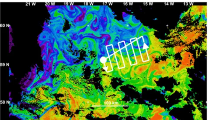
Fig. 1.This example shows chlorophyll concentration in a snapshot image of 11 June 2009 south of Iceland. Here the chlorophyll acts as a tracer of physical structures, mesoscale eddies and “hammerhead” structures, showing stirring of the ocean on scales of 1–50 Km. The UAV survey (taking nine hours) would result in less smearing (be more synoptic) than a ship survey that would take more than thirty hours. Image produced by the NERC Earth Observation Data Ac-quisition and Analysis Service, Plymouth.
1.2 Technology gap
Consequently, although there are UAV systems available commercially, none of these can fulfil our requirements. They cannot operate from a ship in poor weather conditions and the individual vehicle cost is too high, making the im-pact of even a single loss significant to a science mission with limited funding. This leads to the requirement for a new UAV design that can be launched and recovered in poor weather, whose major components can be easily replaced and has a low cost per aircraft reducing the impact of any losses or damage.
2 Motivating marine science applications
The motivating application for the development of this low cost Unmanned Aerial Vehicle is any science where there is a high probability of damage to the vehicle. This could be caused by poor weather in flight but it is most likely that any damage would occur during recovery. In heavy seas when there is a lot of ship motion, it is not deemed possible to re-capture a UAV on deck for safety reasons. Existing systems typically only operate in light conditions. Landing the vehi-cle in the sea will damage many of its components but would allow it to be recovered as research vessel crews have a great deal of experience at retrieving equipment from the water.
As well as using the research vessel as a platform for de-ployment, one of the most useful modes of operation of a UAV could be in supplementing the work already being un-dertaken. This would involve flying ahead of the vessel to allow its research to be more accurately directed to areas of interest. Figure 1 shows a satellite image of remotely sensed
wave breaking and white capping in the open ocean. These processes have a large influence on greenhouse gas ex-change, sea-spray aerosol generation and air-sea fluxes of la-tent and sensible heat (Melville and Matusov, 2002). They are also currently poorly understood. Studying the same pro-cesses in coastal areas would also allow the influence of fetch and wave development to be examined. The critical measure-ment is area coverage of foam, which can be derived from optical imaging (an example analysis is shown in Sect. 5). The sensor package required would be a digital still/video camera with altimetry, orientation, speed and a measurement of the flux profile by the ship. As white capping only occurs where there are winds to create waves, this means it is really only useful to make measurements in conditions Force 3 and above.
3 Designed for low cost
Due to the almost inevitable damage to the vehicle when per-forming the types of missions described in Sect. 2, it is nec-essary for the vehicle itself to be low-cost relative to the value of the data that is collected. At a low enough cost, the vehi-cle is essentially disposable after a single flight so although recovery is preferable, and likely, it is not necessary. This also means that good design leading to long range and relia-bility is important, as the value of the data generated will be increased. However, this does not mean that all the parts of the system need to be low cost, only those most likely to be damaged.
The damage caused by landing in the sea and the subse-quent recovery by the research vessel will be to the large mechanical components, most likely to be damaged are the wing, tail and engine. These must be commodity items, easy to replace and recondition with many of them taken as spares on each trip. The expensive items where replacement must be avoided (the flight control system and payload) are all con-tained within the fuselage. This needs to be buoyant, water-tight and strong to withstand the recovery process.
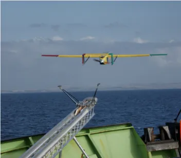
Fig. 2.The NOCS UAV launching from the RRS Discovery, Octo-ber 2008.
taken of a 200 square meter area at 30 ms−1the resulting data
rate is 220 KBps. If the vehicle stays in range of the high-bandwidth 2.4 GHz link for the entire mission (≈10 Km with
omni-directional antenna), it would be possible to transfer the data in real time. However, outside this range, the images could be stored; 6 hours at this data rate creates 5 GB of data, which at close range could be transferred before landing at a rate of 11 Mbps taking 1.2 h. It may be possible to transfer just a subset of the data before landing, for example: every other image, highly compressed images or the processed re-sult from each image (a single value indicating percentage of white capping or other parameter of interest).
The electronic hardware required to fly the aircraft is al-ready a commodity item and can be manufactured for less than £1000. The valuable part of this system is the software component, which may take many years of development to reach a suitable level of sophistication. This makes it ad-vantageous to develop a bespoke flight control system, as the loss of the hardware does not mean having to pay for the repeated software costs associated with buying from a com-mercial provider.
4 Overview of the current system
The UAV developed at the NOC has been designed to meet the requirements set out in Sect. 3. It is a pusher configura-tion with a 3.2-m wingspan, a payload capacity of 2 Kg in a volume of seven litres and a calculated range of more than 1000 Km. This long range is enabled by good aerodynam-ics (lift to drag ratio is greater than 10) and a fuel-efficient propulsion system. The engine is a petrol 4-stroke Saito FG-36, soft mounted on the fuselage to reduce vibration. The
Fig. 3. Image sequence showing the operation of the UAV release on a 15 Kg test mass.
propeller selected after wind tunnel testing was an 18?×18?
and is more than 75% efficient at the cruise condition. To aid landing at sea and reduce impact damage the wing deploys large split flaps, reducing flight speed to below 17 ms−1from
30 ms−1at cruise.
A flight control system has also been developed in-house along with bespoke software algorithms (Bennett, 2007). The waypoint-tracking algorithm continuously minimises the distance between the actual track and the theoretical per-fect track, eliminating the efper-fect of cross wind. This allows fully autonomous flight between waypoints that can be up-dated in real time from the ground control station.
Launch of the vehicle is by elastic powered catapult (Fig. 2); this system has been successfully tested on land in winds gusting to Force 6–7 and at sea in Force 2–3. The launcher is an 8-m track with a scissor action release (Fig. 3) ensuring the vehicle gets away cleanly and that after release the arms lie flat to the track. The launcher can accelerate a mass of 15 Kg to 25 ms−1(peak 6 G), well above the
mini-mum flight speed for the aircraft without needing to deploy the flaps, making it capable of launching even in heavy gust-ing conditions.
Recovery at sea is performed by grappling for the specially reinforced tail boom structure or using an extendable pole with a noose around the fuselage. For the first recovery test at sea, it was possible to collect the vehicle directly using a small launch. The vehicle landed heavily but still floated high with the fuselage sealed and was easy to retrieve. There was damage to the wing and tail as expected (Fig. 4) but it was possible to recondition both components and the engine has subsequently run successfully. The valuable data, payload and flight control system were all safely sealed inside the fuselage and were undamaged.
5 Demonstration deployment
Fig. 4.The NOCS UAV being recovered onto the RRS Discovery. Although the vehicle was damaged, the sealed fuselage protected the valuable payload, data and flight control system.
capping were measured from the images as a demonstration that the vehicle could meet the requirements of the motivat-ing science applications.
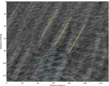
Wave period can be estimated from the images as light from the sun illuminates one side of the wave. This creates a repeating pattern with a period equal to the spatial period of the waves. The dimensions of the image are calculated using the optical properties of the camera and the altitude of the aircraft. The processed image in Fig. 5 was taken at an altitude of 130 m; the wide-angle lens used during the flight gives a resolution of 0.2296 m per pixel.
To calculate the period, first the DC component was re-moved from the image and then a 2D FFT was performed. The FFT was filtered to remove random noise and then a circular dilation filter was applied to enhance the peaks (Fig. 6). The dark areas indicate the most significant fre-quencies present in the image and their direction. Two dis-tinct sets can be identified even in the very calm conditions, one at 19.5 m, 29.8◦, which represents the wind driven sea,
and one at 5.8 m, 73.8◦, which is the most dominant chop
period and direction. This data has been overlaid onto Fig. 5
Fig. 5. Filter wave image with indicators to show the dominant measured wave periods.
Fig. 6.Post filtered two-dimensional FFT of wave image.
where the green indicator lines show the wind driven waves and the blue indicator lines, the dominant chop.
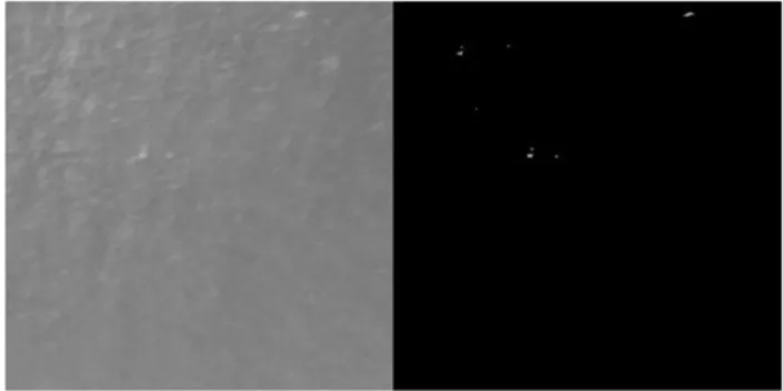
The second type of data measured from the recorded im-ages is percentage white capping fraction. A standard auto-mated process adapted by Moat et al. (2009) from the work of Callaghan and White (2009), was applied to images taken during the flight. The result of this processing is shown Fig.7, giving a calculated white capping fraction of 0.043%. Given the very light conditions on the day of the test flight (3.5–5.4 ms−1, Force 2–3) some whitecapping is possible (Anguelova
Fig. 7.Image processed for white capping measurement (0.043%).
This data processing could be performed after recovery of the vehicle (as in these examples), although it is also possible that this data could be generated in real-time by the payload management system, providing a low rate subset for trans-mission to the ship. This would be in addition to the quality-controlled data generated after recovery, providing instant feedback that could be used to direct the vehicle more pre-cisely.
6 Conclusions
The UAV developed at the NOC has made significant progress in the last four years. A prototype vehicle has been test flown from a NERC research vessel and the autonomous functions demonstrated using a test platform. The vehicle has a low cost of £5,000 excluding payload, software and development. This meets the disposable requirement as part of science mission. It has also launched and flown success-fully in winds gusting to Force 6–7 (over land), which would be considered the minimum conditions for the white capping survey used as an example.
There is some work remaining before the system can be regularly used for scientific measurement. Certification or regulatory requirements require further development with the Civil Aviation Authority, although operating in the deep ocean far from other aircraft and within range of the ship’s radar should not cause an issue. A typical payload package and associated electronics needs to be developed, as well as more testing of recovery techniques. The vehicle is currently not equipped to operate in very cold conditions although this is a possibility that has already been demonstrated by Aerosonde (Curry et al., 2004).
Acknowledgements. The authors would like to thank the un-dergraduate students who contributed to the project as well as Rob Brown of the National Oceanography Centre, Southampton. Many thanks also to Ben Moat, Margaret Yelland, Paolo Cipollini and Robin Pascal of the National Oceanography Centre, Southamp-ton, for their advice regarding the measurement of white capping and wave period.
Edited by: V. Garc¸on
References
Anguelova, M. D. and Webster, F.: Whitecap coverage from satellite measurements: A first step toward modeling the variability of oceanic whitecaps, J. Geophys. Res., 111, doi:10.1029/2005JC003158, 2006.
Bennett, M.: Development of technologies for low-cost oceano-graphic uavs, Doctorate of Engineering, Electronics Computer Science, University of Southampton, 2007.
Callaghan, A. H. and White, M.: Automated processing of sea sur-face images for the determination of whitecap coverage, J. At-mos. Ocean. Tech., 26, 383–394, 2009.
Gull uav capabilities: http://www.centaurseaplane.com/gull/ capabilities.htm, 2007.
Curry, J. A., Maslanik, J., Holland, G., and Pinto, J.: Applications of aerosondes in the arctic, Bull. Am. Meteorol. Soc., 85, 1855– 1861, 2004.
Holland, G. J.: The aerosonde robotic aircraft: A new paradigm for environmental observations, Bull. Am. Meterol. Soc., 82, 889– 902, 2001.
Scaneagle/seascan uav specifications: http://www.insitu.com/prod scaneagle.cfm, 2007.
Lin, P.-H. and Lee, C.-S.: The eyewall-penetration reconnaissance observation of typhoon longwang (2005) with unmanned aerial vehicle, aerosonde, J. Atmos. Ocean. Techn., 25, 15–25, 2008. Lomax, A. S., Corso, W., and Etro, J. F.: Employing unmanned
aerial vehicles (uavs) as an element of the integrated ocean observing system, OCEANS, Proceedings of MTS/IEEE, 181, 184–190, 2005.
McGeer, T. and Holland, G. J.: Small autonomous aircraft for eco-nomical oceanographic observations on a wide scale, The maga-zine of the Oceanography Society, 6, 129–135, 1993.
Melville, W. K. and Matusov, P.: Distribution of breaking waves at the ocean surface, Nature, 417, 58–63, 2002.
Moat, B. I., Yelland, M. J., and Pascal, R. W.: Oceanic whitecap coverage measured during uk-solas cruises, 16th Conference on Air-Sea Interaction, Phoenix, USA, 2009,
Peterson, D. L., Brass, J. A., Smith, W. H., Langford, G. S. W., Dunagan, S., Hammer, P., and Snook, K.: Platform options for free flying-satellites, uavs or the iss for remote sensing assesment of the littoral zone, Int. J. Remote Sens., 24, 2785–2804, 2003. Pluck, G., Waugh, E., Gilbertson, R., Hoen-Teng, L., Roberts, S.,
McKinley, M., and Hatts, D.: An unmanned aerial vehicle for oceanographic applications, Masters of Engineering, School of Engineering Sciences, University of Southampton, UK, 2003. Uavs: Out of uniform: http://www.aviationtoday.com/av/