Abstract—To realize accurate and reliable positioning in completely GPS-denied environments is the main challenge for land vehicles. A two-level extended Kalman filter (EKF)-based vehicle positioning strategy is proposed, which can fuse the data obtained from the radio frequency identification (RFID) and the in-vehicle sensors. First, the RFID-based preliminary positioning algorithm is developed. The received signal strength is used as an indicator to calculate the ranges between the RFID tags and reader, and then the vehicle’s location is preliminary calculated by using the first level EKF. Further, to improve the positioning performance, the improved vehicle motion model is established, and the second level EKF algorithm is designed to fuse the preliminary positioning results and the in-vehicle sensors information. Finally, the proposed strategy is evaluated through experiments. The results validate the feasibility and effectiveness of the proposed strategy.
Index Terms—RFID, fusion positioning, EKF, in-vehicle sensors
I. INTRODUCTION
OR vehicle positioning, global positioning system (GPS) is the most widespread used technology [1],[2]. However, GPS may suffer from signal interruption or multipath [3] in GPS-denied environments which may decreases the positioning accuracy and reliability. To overcome the signal blockage of GPS, one common solution is that GPS is integrated with an inertial navigation system (INS) [4] or dead reckoning (DR) [5]. Owing to the measurement biases and integration processes, the INS and DR will accumulate large errors over time. These large errors may cause the rapid performance degradation during GPS outages. Other in-vehicle sensors such as vehicle motion sensors [6] can be used to compensate for the errors. However, the compensation effect is limited when GPS is in a long-time failure. The main reason is that the lack of the position
Manuscript received May 16, 2015; revised October 10, 2015.
This work was supported by the National Natural Science Foundation of China under Grant 61273236, the Jiangsu Planned Projects for Postdoctoral Research Funds under Grant 1401012C, the Fundamental Research Funds for the Central Universities under Grant 2242015R20017, and the Project Funded by China Postdoctoral Science Foundation under Grant 2015 M 571631.
Xiang Song and Weigong Zhang are with the School of Instrument Science and Engineering, Southeast University, Nanjing, Jiangsu China. (e-mail:[email protected], [email protected]).
Xu Li is corresponding author with the School of Instrument Science and Engineering, Southeast University, Nanjing, Jiangsu China.(phone:8613601463199; e-mail: [email protected]).
Wencheng Tang is with the School of mechanical Engineering, Southeast University, Southeast University, Nanjing, Jiangsu China. (e-mail: [email protected]).
observation to correct the errors.
As an alternative, there has been rapid development of wireless location technologies [7], [8], [9] in recent years. Among them, Radio Frequency Identification (RFID) has attracted widely attention and become a possible solution to obtain object’s location information in indoor environment [10], [11].
RFID can provide the location information in non-GPS environments. However, only the RFID cannot achieve high positioning performance for outdoor vehicle application due to the severe nonlinearities in vehicle operation process, i.e., both the accuracy and output frequency are not enough high to meet the requirement for many location-based applications In addition, RFID can only provide the position information, but they cannot provide the speed or attitude information which is also important to the location-related vehicle services.
DR is a widely used vehicle positioning technology that uses the driving direction and speed to reckon the position of vehicle. DR has the advantage that it is totally self-contained. Consequently, it is always capable of providing the vehicle with an estimate of its position. However, this method suffers serious accumulative errors. These large errors are strongly time correlated and can cause the rapid performance degradation due to the lack of position observation.
To overcome the disadvantages and combine the advantages of RFID and DR method to achieve more accurate and reliable positioning performance, the multi-sensor fusion method [12], [13] provides us a viable solution. Due to the complementary natures of these two types of sensors, the RFID can be fused with several in-vehicle DR sensors to realize positioning in completely GPS-denied areas. In other words, RFID can provide the position observation to correct the accumulative integration errors of DR, and DR can provide speed and attitude information of vehicle to improve the positioning accuracy and output frequency of RFID. However, to the author’s best knowledge, there has been little relevant research on the topic of fusion positioning specialized for vehicle by using RFID and in-vehicle sensors.
II. PROBLEM DESCRIPTION AND RESEARCH METHODOLOGY This paper aims to propose a fusion strategy for vehicle positioning based on RFID and in-vehicle sensors in completely GPS-denied environments. This strategy adopts a two-step approach, namely, the preliminary positioning based on the RFID and then the further fusion positioning.
RFID Application for Vehicle Fusion Positioning
in Completely GPS-denied Environments
Xiang Song, Xu Li, Weigong Zhang, andWencheng Tang
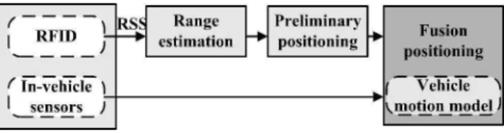
To obtain higher performance, the algorithms for both preliminary and fusion positioning are developed. The proposed fusion strategy is shown as Figure 1.
The in-vehicle sensors include odometer, digital compass, two orthogonal accelerometers and a yaw gyro. In this paper, two-level extended Kalman filter (EKF) is developed to achieve positioning.
In the preliminary positioning, the received signal strength (RSS) of RFID is employed as the indictor to estimate the range from the vehicle to the RFID tags. Then the first level EKF is employed to preliminary compute the vehicle’s location.
In the further fusion positioning, the low cost in-vehicle sensors are integrated with the preliminary positioning results utilizing the second level EKF. Due to the in-vehicle sensors, the positioning performance can be improved, i.e., the accuracy and output frequency are enhanced, the velocity and attitude information can be provided. Meanwhile, to describe the vehicle motion more accuracy, an improved vehicle motion model is established in the fusion process.
III. PRELIMINARY POSITIONING A. Range Estimation Algorithm
It seems that the first challenge of preliminary positioning is how to mathematically model the nonlinear relationship between the RSS and the range. Theoretically, under ideal environments, Friis transmission equation [11] can be applied to model the nonlinear correlation. However, in real applications, this model is not satisfied due to the environment effect. This paper proposes a least square support vector machine (LSSVM) algorithm [14], [15] to model the relationship. Compared with the propagation model, the proposed LSSVM algorithm has many advantages, such as high precision, high generalization ability and strong adaptability for different environments, which can significantly improve the subsequent positioning performance. The input of LSSVM is RSS, and the output is the range. The training data is collected through experiments in different situations. The training process is off-line, and then the trained LSSVM is used to estimate the range on-line.
Given a training set
,
N1 k k kx y , where xk is input RSS vector, yk is output range vector. , 1
k k
x y R , R1 is the one-dimensional vector space. In feature space, the LSSVM model takes the form:
f x( )ωT x b (1)
mapping (.) :R1Rnh maps the input data into a higher dimensional feature space; b is the scalar threshold.
The optimization problem is
2
1
1 1
min ( , , )
2 2
N T
k k
J b e e
ω ω ω (2) Due to the equality constraints:
T ( ) , 1, ,
k k k
y ω x b e k N (3) where ek is the error variable and
0 is a regularizationconstant. To solve the optimization problem above-mentioned, the Lagrangian function is introduced:
2
1 1
1 1 ( )
2 2
N N
T T
LS SVM k k k k k
k k
L e b e y
ω ω
ω X (4)wherekare the Lagrange multipliers, according to Karush Kuhn Tucker(KKT)optimization conditions which are illustrated in Equation (5):
1
1
0 ( )
0 0
0 , 1, ,
0 ( ) 0, 1, ,
N LS SVM k k k N LS SVM k k LS SVM k k k T LS SVM
k k k
k
L x
L b
L e k N
e
L x b e y k N
ω ω ω (5)Eliminating ω and ek will yield a linear system instead of a quadratic programming problem:
0 0 / T N N N b 1 α Y
1 Ω I (6)
where
1, ,
T,
1, ,1
TN N
y y
Y 1 and
1, ,
TN
α .
N
I is a N N identity matrix. Ω is the kernel matrix defined by
( ) ( )T ( , )
ij xi xj K x xi j
Ω ,i j, 1, , N (7)
The radial basis function (RBF) has been used here as the kernel function ( , )K , which is given by
22
2
( , ) exp , 1, ,
2
k k
x x
K x x k N
(8)
where x x k 22 is the squared Euclidean distance between the two feature vectors; is the width of RBF.
Further, the result of the LS-SVM model for function estimation becomes
1
( ) N k ( , )k
k
f x K x x b
(9) where k and b are the solutions to Equation (6). The design values of and can be determined during the training of LSSVM.After off-line training, Equation (9) can be used to on-line estimate the range between the tag and the reader according to the measured RSS.
B. Positioning Algorithm
The first level EKF is developed to preliminary determine the position of vehicle by using the estimated ranges. Assumed that i tags with known coordinates (xi, yi) are
detected by the reader at the time k, and the ranges from these tags to the vehicle are ri. The state equation and measurement
equation can be described as:
R R R R
R R R R
-1 + -1
= +
k k k
k k k
X A X W
Z h X V
(10) where k is the discrete-time step; XR
k =e k
n k indicates the state vector, e and n are the east and north coordinates of the vehicle; the state transition matrixR 1 0 = 0 1
A ; WR and VR are the system and measurement
noise and their covariance matrices are QR and RR;
R r k1 ... r ki
Z is the observation vector and
R k h k1 ... h ki
h is the corresponding
observation function,
2
2+ i
i i i r
h k e k x k n k y k n ,nri denotes the corresponding observation noise vector with the assumption of the zero-mean and Gaussian distribution.
Then the execution of EKF [16], [17] can be divided into time update stage and measurement update stage as follows:
Time update:
XˆR( ,k k 1) A XRˆR(k1) (11) R( ,k k 1) R( ,k k1) ( 1)R k R( ,k k 1) R( 1)k
P A P A Q (12) Measurement update:
1R( )k R( ,k k 1) ( )1 k RFID( ) ( ,k R k k 1) R( )k R( )k
K P H H P H R (13)
R R R R R R
ˆ ( )k ˆ ( ,k k 1) ( )k ( )k ˆ ( ,k k1)
X X K Z h X (14)
PR( )k
I KR( )k HR( )k
PR( ,k k1) (15) where I is an identity matrix, HR is the Jacobian matrix of themeasurement function hR
with respect to XR
1 1 1 1
R
N N N N
e k x k D k n k y k D k
k
e k x k D k n k y k D k
H
,D ki
e k
x ki
2
n k
y ki
i1,2,...,N
. Since only the RFID is employed, this algorithm can onlyprovide the position information, and the positioning accuracy and output frequency are not high enough, i.e., the output frequency is always no more than 1Hz.
IV. FUSION POSITIONING A. Vehicle Motion Model
To describe the typical vehicle motion, an improved vehicle motion model is established. The state vector is
k =e k
n k v ke
v kn
k X
where v ke
and v kn
denote the east and north speeds ofthe vehicle.
k is the yaw angle. The system input vector, i.e., the longitudinal and lateral accelerations ax, ay , and theyaw rate
z, are measured by the accelerometers and yaw gyro. Defineda ke
1
axcos
k 1
aysin
k1
and
1
sin
1
cos
1
n x y
a k a k a k ,the motion model is shown as:
2 2 11 1 1
2
1 1
1
, 1 1 1 1
2 1 1 1 e e e n n n z
e k v k T a k T
e k a k T
k k n k v k T a k T
n k a k T
k
X (16)
B. Fusion Algorithm
The second level EKF is developed to fuse the data obtained from RFID and in-vehicle sensors for further positioning. Defined the observation vectorZ
xRFID yRFID vo c
, it can be seen that Z comes from two sources, i.e., xRFID and yRFID are the estimated vehicle’s coordinates by first level EKF;vois the vehicle speed measured by odometer, c is the observed yaw angle from the compass.
cos sin pe pne n v
e k n n k n k
v k k v k k n
k n
Z h X (17)
where h is the observation function.npe,npn,nv and n are
the observation noise vectors. By utilizing EKF algorithm as equation (11)-(15), the fusion positioning can be achieved.
V. EXPERIMENTS AND RESULTS
The verification experiments were conducted in the simulated tunnel which was set in the outdoor open space. Only one experimental result is shown here as an instance because similar conclusions can be drawen by other tests. In the experiment, the output frequency of RFID hardware devices is 1Hz. The RSS range of tag is normalized to 0-255, and the maximum measured distance of tag is 9m.
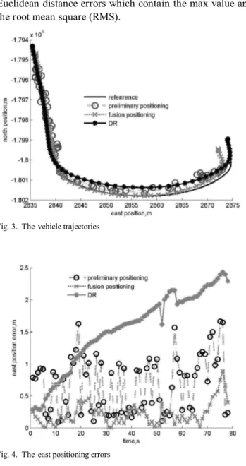
Figure 3 shows the trajectories of the vehicle, and Figure 4 illustrates the east position errors from preliminary and fusion positioning. For comparison, the widely used DR method is also investigated. Table I gives their performances, i.e., the output frequency, the speed and the statistics of Euclidean distance errors which contain the max value and the root mean square (RMS).
The reference trajectory was measured by high precision differential GPS. Figure 3, Figure 4 and Table I show that the fusion positioning performance is obviously better than preliminary positioning and DR. Compared with DR, the RMS value of Euclidean distance error of the proposed strategy is decreased to 3.78m, i.e., about 27% accuracy improvement over DR. It can be attributed that the RFID can provide the position observation to correct the accumulate errors of DR. Compared with the preliminary positioning algorithm, the RMS value of Euclidean distance error of the proposed strategy is reduced to 3.78m from the value 4.47m, and the output frequency is increased to 10Hz from the value 1Hz. Meanwhile, the speed and the attitude information can be provided. The main reason is that the in-vehicles sensors can provide accurate speed and attitude information to enhance the positioning accuracy and reliability,
Compared with the low-cost GPS which is most widely used in the vehicle, the proposed fusion positioning strategy has the approximation accuracy with higher frequency. Therefore, when GPS is completely unavailable, the proposed strategy can satisfy the common demand of vehicle positioning.
VI. CONCLUSION
In this paper, RFID is employed to locate the vehicle in completely GPS-denied environments. Meanwhile, the in-vehicle sensors are introduced to improve the observability of RFID. A vehicle positioning strategy based on two-level EKF is proposed to fuse the data obtained from RFID and in-vehicle sensors. Experiments were performed to verify the effectiveness of the proposed strategy. The experimental results indicate that the proposed strategy achieves remarkable performance improvement in completely GPS-denied environments.
REFERENCES
[1] I. Skog, P. Handel, “In-Car Positioning and Navigation Technologies — A Survey,” IEEE Transaction on Intelligent Transportation Systems, vol.10, no.1, pp. 4-21, 2009.
[2] J. Georgy, A. Noureldin, M. J. Korenberg, M.M. Bayoumi, “Low-cost three-dimensional navigation solution for RISS/GPS integration using mixture particle filter,” IEEE Transaction on Vehicular Technology, vo1.59,no.2,pp. 599-615, 2010.
[3] T. H. Chang, L. S. Wang, F. R. Chang, “A solution to the ill-conditioned GPS positioning problem in an urban environment,” IEEE Transaction
on Intelligent Transportation Systems, vol.10, no.1, pp. 135-144, 2009.
[4] D. Bhatt, P. Aggarwal , V. Devabhaktuni, P. Bhattacharya, “A novel hybrid fusion algorithm to bridge the period of GPS outages using low-cost INS, ” Expert Systems with Applications, vol.41, no.5,pp. 2166-2173, 2014.
[5] R. Toledo-Moreo, M. A. Zamora-Izquierdo, B. Ubeda-Miarro, “High-integrity IMM-EKF-based road vehicle navigation with low-cost Fig. 3. Thevehicle trajectories
TABLEI
THE POSITIONING PERFORMANCE
Method Euclidean distance error Speed Frequency (Hz) MAX(m) RMS(m)
Preliminary 13.19 4.47 No 1 Fusion 6.23 3.78 Yes 10 DR 10.14 5.21 Yes 10
[6] K. Jo, K. Chu, M. Sunwoo, “Interacting Multiple Model Filter-Based Sensor Fusion of GPS with In-Vehicle Sensors for Real-Time Vehicle Positioning,” IEEE Transaction on Intelligent Transportation Systems, vol.13, no.1, pp. 329-343, 2012.
[7] C. Rohrig, C. Kirsch, J. Lategahn, M. Muller, “Localization of Autonomous Mobile Robots in a Cellular Transport System,”
Engineering Letters, vol.20, no.2, pp. 148-158, 2012.
[8] B.L. Wei, C. Xiong, H.W. Yue, X.M. Wei, W.L. Xu, Q. Zhou, J.H. Duan, “Ultra wideband wireless propagation channel characterizations for biomedical implants,” IAENG International Journal of Computer Science, vol. 42, no. 1, pp. 41–45, 2015.
[9] K. Phuchong, K. Somsak, IAENG International Journal of Applied
Mathematics, vol. 43, no. 1, pp. 30–36, 2013.
[10] S. L.Ting, S. K. Kwok, A. C. Tsang, “The Study on Using Passive RFID Tags for Indoor Positioning,” International Journal of
Engineering Business Management, vol. 3, no. 1, pp. 9–15, 2011.
[11] J. Y. Zhou, J. Shi, “RFID localization algorithms and applications—a review,” Journal of Intelligent Manufacturing, vol. 20, no. 6, pp. 695-707, 2009.
[12] A. A. Fathima, S. Vasuhi, N.T. Babu, V. Vaidehi, “Fusion framework for multimodal biometric person authentication system,”IAENG
International Journal of Computer Science, vol. 41, no. 1, pp. 18-31,
2014.
[13] X. Li, W. G. Zhang, “An Adaptive Fault-tolerant Multisensor Navigation Strategy for Automated Vehicles,” IEEE Transaction on Vehicular
Technology, vo1.59, no.6, pp. 2815 – 2829, 2010.
[14] V. Khryashchev, L. Shmaglit, M. Golubev, A. Shemyakov, “The development of object tracking and recognition algorithms for audience analysis system,” IAENG International Journal of Computer Science, vol. 40, no. 2, pp. 94-103, 2013.
[15] Z.H. Zhong, D.C. Pi, “Forecasting satellite attitude volatility using Support Vector Regression with Particle Swarm Optimization,” IAENG
International Journal of Computer Science, vol. 41, no. 3, pp. 153-162,
2014.
[16] T.O. Ting, K.L. Man. C,U, Lei, C. Lu, “State-of-charge for battery management system via Kalman filter,” Engineering Letters, vol.22, no.2, pp. 75-82, 2014.