Design and Implementation of Air Conditioning
System in Operating Room
Htet Htet Aung 1
, Hla Myo Tun
21 2Departmentof Electronics and Communication Engineering 1HtetHtetAung
2
HlaMyoTun
Abstract-The system is air conditioning system in operating room. The main objective of the system was implemented to provide air balance and temperature necessary conditions and to control airflow system for ventilation units in operating room. The operation room can be controlled with fuzzy expert system and describes the desired outputs. Input parameters such as temperature, humidity, oxygen and particle are used and output parameters are chosen as air conditioning motor speed and exhaust motor speed. Input parameters of the system are taken into account optimal conditions based on oxygen as medium and other parameters are chosen minimum condition for operating room. The airflow control system is determined the two components: the airflow block and the thermal block for ventilation units in operating room. The mathematical modeling of each such system based on a computational procedure and to combine them together in an efficient manner. Whether it supports to the most suitable control for the system prototype was determined by simulating the operation with varying the number of personnel and duration of time. Finally, according to the combination of temperature and airflow regulations with PI controller, the results of simulation of the entire ventilation unit control system is obtained.
Keywords- Fuzzy controller, operating room, airflow control, ventilation unit, simulation
I.INTRODUCTION
Nowadays, the air conditioning system is widely used in many countries. The air conditioning system of operating room is important for patient and staff. Fuzzy logic controller in air conditioning system provides a comfortable environment together with energy save [1]. Fuzzy expert system was used in the control of operating rooms where complex and uncertain parameters play a crucial role. Air condition and ventilation system for hospital have some standards and publications. These standards, the design of hospital air condition and ventilation system and the technical specifications of the device are taken into account [2]. This system discusses an implementation of a fuzzy inference unit and algorithms for fuzzification, rule-based and defuzzification of a fuzzy control system for air conditioning system. There are many fuzzy inferences however in this article Mamdani inference mechanism was favored as it both easy and suitable for the system design of fuzzy system. The overall block diagram is shown the control system for operating room. It consists of three portion: Fuzzy logic controller, operating room and feedback sensor.
The four input parameters such as temperature, humidity, oxygen and particle are specified as the followings, Temperature(low) 0≤ a ≤ 18, Humidity (low) 0≤ a ≤ 15,Oxygen (medium) 17≤ a ≤ 25, Particle (low) 0≤ a ≤ 280 which is applied to the FLC. It has four modules which consist of fuzzification, rule - based, inference engine and defuzzification. The process comprises the operating room related to the ventilating air can be considered as temperature control and airflow control. The ventilation unit in operating room is predefined conditions. An essential feature for laying out air conditioning systems is air flow, which can be designed to be constant or variable. The system selected depends on the overall concept of the operating room. A constant system is only possible where other systems ensure zone-based temperature control, e.g. the heating surfaces, or where temperature control
is not required [9]. Therefore, a closed-loop control system for airflow regulation applied with conventional PI
airflow control system is stable and accurate [5]. If the process system meets the specific condition, the outputs corresponding with inputs will be generated. Otherwise, the sensor section senses the predefined conditions and then sends to the fuzzy logic controller.
T=
Temperature, H= Humidity, P= Particle, O= Oxygen, ACM= Air Con speed Motor, EM= Exhaust Motor
Figure 1.Overall block diagram of air conditioning system for operating room
Nomenclature
dtip fan diameter(m) Cfpressure coefficient
ύ volumetric airflow (m3/s) C
p specific heat of air at constant pressure(J/kg ◦C)
N number of speed (rpm) VR volume of the room (m3)
C thermal capacity λwall heat conduction coefficient (W/mK)
Aduct area inside duct(m2) µ absolute viscosity coefficient (kg/ms)
Re Reynolds number mc. mass flow rate of cold air(kg/s)
ρ density(kg/m3) ρf density of filter material( kg/m3)
λ friction factor
II.DEVELOPMENTOF FUZZY RULE FOR OPERATING ROOM AIR CONDITIONING SYSTEM
In that system, temperature, humidity, oxygen and particles are used as inputs parameters and adjusted air conditioning motor speed and exhaust motor speed.Fuzzy rules are developed and based on the situation of operating room. As there are four inputs parameter and three levels for each input, total of 81 rules are fashioned. For the inference mechanism the Mamdani min-max inference is used. In defuzzification process, Center of Gravity or centroid method (COG) is used. It presents better performance with short time and dynamic response very close to the one an efficient. The four inputs have been classified into three levels of Low, Medium and High for each. And then, triangular membership function is used for each input’s membership function.
Number of active rules= m, m= maximum number of overlapped fuzzy sets, n= number of inputs
According to the data taken from the user, the system calculates the situation in operating room using fuzzy rule_ base is shown in Table-1.
This is the most widely used Center of Gravity method. It can be defined by the algebraic expression:
)
1
...(
).
(
*∫
=
z
zdz
For input parameters (low),
Numerator → + .
. . +
.
. .
. . .
. .
. =116.897
Denominator → + .
. . +
.
. .
. . .
. .
. =7.569
∗=116.897
7.569 = 15.4
For output parameter,
For Low, Numerator → + =271666.6
Denominator→ + =300
∗=271666.66
300 = 905.55
For Medium, Numerator → ( ) + =230000
Denominator→ + = 200, ∗= = 1150
For High, Numerator → ( ) + " =497083.33
Denominator→ ( ) + " =350, ∗= # . = 1420.25
Humidity (LOW) 0≤ a ≤ 15 Oxygen (LOW) 0≤ a ≤ 17 Particle (LOW) 0≤ a ≤ 280
For Output,Air con motor speed & Exhaust motor speed --- High (1350 ≤ a ≤1600)
Table-1The Fuzzy Rule Base
Number Inputs Outputs
Temperature Humidity Oxygen Particle ACMS EMS
1 L L L L H H
2 L L L M H H
3 L L L H H H
4 L L M L L L
5 L L M M M M
6 L L M H H H
7 L L H L H H
… … … …
… … … …
77 H H M M M M
78 H H M H H H
79 H H H L M M
80 H H H M M M
81 H H H H H H
L=Low, M=Medium, H=High, ACMS=Air con Motor Speed, EMS=Exhaust Motor Speed
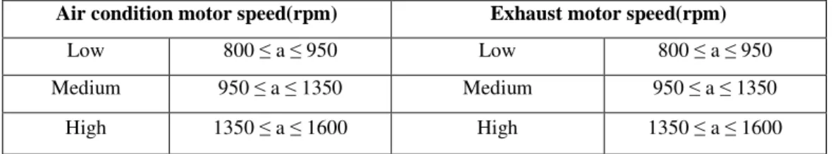
Table-2 and- 3Membership Function for Inputs and Outputs
The relationship between inputs and outputs of the membership values are assigned the following specification.
Temperature(◦C) Humidity (%) Oxygen (%) Particle(ppm)
Low 0≤ a≤ 18 Low 0≤ a≤ 15 Low 0≤ a≤ 17 Low 0≤ a≤ 280
Medium 18≤a≤ 24 Medium 15≤ a≤ 33 Medium 17≤ a≤ 25 Medium 280≤ a≤ 380
Air condition motor speed(rpm) Exhaust motor speed(rpm)
Low 800 ≤ a ≤ 950 Low 800 ≤ a ≤ 950
Medium 950 ≤ a ≤ 1350 Medium 950 ≤ a ≤ 1350
High 1350 ≤ a ≤ 1600 High 1350 ≤ a ≤ 1600
III.MATHEMATICAL MODELING FOR VENTILATION UNIT OF THE ENTIRE SYSTEM
Temperature and airflow are the main parameter in this sequence and the procedure which takes place as a controlling sequence. In a closed –loop control system have two parts that are controlled the outlet temperature from the heat recovery model and the airflow of the supply and exhausted air from the air flow model. The system is applied with conventional PI controllers and the performance of the entire control system. This control system includes a number of different models which are linked together. Some of their inputs/outputs can develop from externally.
(1) Frequency Converter
The frequency converter is controlled to start and stop the motor using a ramp function for the performance of frequency converter. The frequency converter of the system can be defined as
Freq=
$ %
&$% …. (2)
Where, Freq = require frequency, G = gain,S = saturation
Figure 2.Schematic block diagram of frequency converter model in SIMULINK
(2) AC motor
When AC voltage is applied to the stator current flow through the windings and then a rotating magnetic field will be generated in the space between stator and rotor and the speed will be produced between the rotating magnetic field and the stator. Three phase induction motor for the motor speed can be defined as
n=120*f (1-s)/p …. (3)
Where, n=rotor speed (rpm), p=number of pole for Ac motor, f= frequency, s=slip. The functional block in
Figure 3.Schematic block diagram of AC motor model in SIMULINK
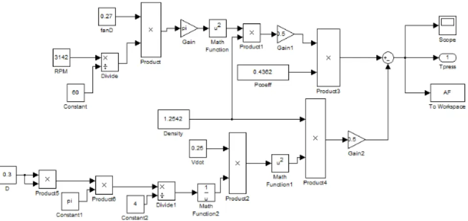
(3) Air Axial Fan
The function block for the fan is constructed on the based on eqn(4) and one can be calculated the performance of the fan with the developed model.
Ptotal=1/2ρ[πdtipN/60]2ψ+1/2ρ[υ./Afan]2 …(4)
Where Ptotal=total pressure difference between input and output (Pa), Afan=area of the fan (m2), υ. = volumetric
airflow (m3/s), ρ=inlet density at the fan face (kg/m3), N=fan speed (rpm), dtip =fan diameter (m)
Figure 4.Schematic block diagram of axial fan model in SIMULINK.
(4) Ductwork
The duct model is implemented through the function block construction in SIMULINK with depended on eqn(5) ΔPduct,loss=(λL/D+Σξ)ρ/2(ʋ./A)2 ….(5)
Where, λ=friction factor, ξ=local hydraulic coefficient
For a laminar flow (Re≤ 2300), the friction factor can be determined as eqn
λ=64/Re …. (6) Re= ρ υ D/µ …. (7)
Figure5.Schematic block diagram of ductwork model in SIMULINK
(5) Air Filter
The temperature of flowing air varies with a pressure drop, induced by the airflow. The bigger the pressure difference over the filter will be, the faster velocity of the airflow is. The pressure drop can be defined as follows: ΔPpressure,drop=Cfρf½ [υ./Aduct]2 …. (8)
Where,ΔPpressure,drop= pressure drop over the filter(Pa), Cf= pressure loss coefficient of filter, ρf =density of filter material (kg /m3 ). The function block is presented a SIMULINK implementation for the computation of the pressure drop over the filter. The relationship between the pressure difference and the volumetric airflow will be established as the output of the plant model.
υ. =√ ΔP
total/C1 +C2 -√ C2 …. (9)
Where ΔPtotal=total air pressure (Pa), C1, C2 are constants taken as C1= 3003, C2=0.000782 respectively.
The function block developed on the basic of (9) acts as the feedback conversion component within the entire
control system.
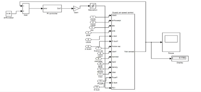
(6) PI Controller
The airflow control system, the proportional was set at 0.003, while the integral gain was set 20. A proportional
controller will be applied to reduce the rise time and steady- state error. The function block for the airflow plant
model by adding a PI controller in SIMULINK is implemented. The relationship between the proportional
controller and integral gain is based on
GPI(s) =KP + KI /s ... . (10)
Where, KP = the control gain of the proportional, KI = the control gain of the integral
Figure 7.Schematic block diagram of PI controller for airflow control system
The airflow control system of test da
Table-4 Param
1 Air flow Set poin
2 Density of air
3 Diameter of duct
4 Pole
5 Slip
6 Diameter of fan
7 Friction resistance
8 Length of the duc
9 Pressure coefficie
10 Output temperatu
Figure.9(a) represents the frequ function. When the user sets the inp saturation value can be controlled th and then gradually reaches at remain
According to figure.9 (b), the AC
from Frequency converter is applied
As represented by figure.9(c), th
airflow, density of air and properties
(a)
Figure.9 (a) Simulation of frequency converte SIMULINK (c) Simulation of ax
data listed in Table-4.
ameters Specifications for constant airflow system at a specific conditi
oint 0.35m3/s
1.2542kg/m3
ct 0.3m
2
0.03
0.27
nce factor inside duct 0
uct 1m
cient of air fan 0.4362
ture from heat exchanger 20°C
IV. SIMULATION RESULTS AND DISCUSSION
quency converter is controlled in order to start and input frequency as ramp function 53Hz is applied to ga the required frequency. According to the result, a ramp ain constant.
AC motor of speed is obtained with around 3142 rpm d
ied to feed gain and slip and pole are chosen 0.03 and 2 r
the total pressure depends on the relationship between
ies of the fan is determined in developed model.
(b)
erter model in SIMULINK for soft start by using a ramp function (b) axial fan model in SIMULINK
dition
d stop motor using a ramp gain in which determine the p function between 0 to 25s
m due to the attain frequency
2 respectively.
n the input and output of the
(c)
(a) (b) Figure.10 (a) Simulation of ductwork system model in SIMULINK (b) Simulation of air filter model in SIMULINK
The figure.10 (a) shows the output of total pressure drop is determined by the area of duct model, friction resistance
factor, airflow, temperature.
Figure.10(b)illustrates the outcome of the pressure drop over the filter can be influenced by the input airflow,
pressure coefficient of filter and density of filter. The more rapidly the velocity of the airflow (is), the greater the
pressure difference over the filter (will be).
V.CONCLUSION
In operating room of air conditioning systems have been done by using fuzzy control system. These air conditioning systems have been provided a more comfortable environment for the patient and staff. The airflow control system is essential for ventilation units in operating room. Laminar airflow used the required place such as near the operating room table without giving the overall operating room in order to save energy depletion and reduce spread of diseases. The active attained from simulation with mathematical models advanced for each such block has been associated with the measurement and experimental data. Finally, the difference between the test results and the experimental results has been found due to neglect the thermal properties of duct model.
REFERENCE
[1] N.Etik. (2009). Fuzzy expert system design for operating room air-condition control systems .An International journals. Konya. Turkey ... [2] I .Saritas, (2003). Fuzzy control of medical area. Master thesis, Selcuk University, Konya,Turkey.
[3] Fuzzy logic control system
[4] Foundations of Fuzzy Control, wiley (2007)
[5] Wu Z, Melnik RVN, Borup F. Model-based analysis and simulation of airflow control systems ventilation units in building environments. MCI technical report, University of Southern Denmark; 2003.
[6] Wu Z, Melnik RVN, Borup F. Model-based analysis and simulation of regenerative heat wheel. MCI technical report,University of Southern Denmark; 2003.
[7] Alcala R, Benitez JM, Casillas J, Cordon O, Perez R. Fuzzy control of HVAC systems optimized by genetic algorithms. Applied Intelligence2003
[8] F. Steimle, J. Ro¨ben, Ventilation requirements in modern buildings, Proceedings of the 13th AIVC conference, Nice, France, 1992, [9] [Available online], www.troxtechnik.com,accessed on December,2013.