Abstract—Achieving thermal comfort with minimum energy consumption is the main requirement in designing an air-conditioning system. This research study about the variable compressor speeds to increase energy efficiency with better temperature control. The usage of on/off controller consumes large energy as the compressor is working at the maximum speeds, and it turns on and off when it achieved the temperature setting, causing high-energy usage. Variable-speed compressor controller will constantly vary the compressor speed to reach the temperature setting. The experiment is done in a thermal environmental room for a controller system to implement the controller algorithms with temperature setting of 23 and 24°C with internal heat loads of 1000 W. Data acquisition system is implemented to monitor of the room temperature, energy consumption, energy saving and coefficient of performance. The proposed variable-speed compressor system indicates more energy savings with better temperature control compared to on/off controller system.
Index Terms—Split unit air conditioning, coefficient of performance, variable speed, energy efficiency, fuzzy logic control.
I. INTRODUCTION
HERE are different types of air conditioner (AC) in the market nowadays namely windows AC, split, tower, cassette and cube AC. These ACs installed in various spots in the room that need to be cool, for example, at windows, on ceiling and some space on the floor. The application of AC has expanded through the years. Not only AC in the house, but nowadays it being used in a larger area like building, and big lecture hall. All of these usages come to
Manuscript received December 29, 2014; revised January 26, 2015. This work was supported by Universiti Teknologi Malaysia: Knowledge Transfer Program (KTP) No. R.J130000.7809.4L509 and Automotive Development Center, Ministry of Education (MOE) Malaysia.
H. Nasution is with Automotive Development Centre, Faculty of Mechanical Engineering, Universiti Teknologi Malaysia, 81310 UTM Johor Bahru, Johor, Malaysia (corresponding author phone: 607-553-5447; fax: 607-553-5811; e-mail: [email protected]).
A. A. Dahlan is with Faculty of Mechanical Engineering, Universiti Teknologi Malaysia, 81310 UTM Johor Bahru, Johor, Malaysia (e-mail: [email protected]).
A. M. Nasib is with Faculty of Mechanical Engineering, Universiti Teknologi Malaysia, 81310 UTM Johor Bahru, Johor, Malaysia (e-mail: [email protected]).
A. A. Aziz is with Automotive Development Centre, Faculty of Mechanical Engineering, Universiti Teknologi Malaysia, 81310 UTM Johor Bahru, Johor, Malaysia (e-mail: [email protected]).
Sumeru is with Department of Refrigeration and Air Conditioning, Politeknik Negeri Bandung Gegerkalong Hilir Ciwaruga Bandung 40012, Indonesia (e-mail: [email protected]).
one objective that is to provide a comfortable condition to stay in by adjusting to the temperature setting.
Conventional split AC system operates at constant compressor speed to achieve a desired temperature. Thus to achieve this it turns the compressor off and on repeatedly and will be leading to wasteful energy consumption. Most of AC systems used in countries like Malaysia operated at constant compressor speed. The selection of this type of AC is mainly based on capital cost of the equipment and the use of the control system to save electrical energy is not the main objective [1].
The use of the variable-speed drive (VSD) on AC is a development from the conventional AC. By using this VSD, the speed of compressor can be control depending on the heat load and this will result in less energy consumption. By changing the frequency of the motor that drives the compressor, the systems with variable-speed compressor (VSC) able to control the room-temperature [2-4].
A VSD functions by converting the incoming electrical supply of fixed frequency into a variable frequency output. The driver can control the incoming frequency to control the way of the compressor operates – a low compressor speed runs at low frequency, and a faster compressor speed runs at higher frequency. Furthermore, the output can also be changed to enable the compressor to generate variable torque as required. In other words, it matches the amount of energy of the compressor need to the amount of work that being done. The compressor can turn into a suitable speed depending on the workload.
Heating, ventilation and air conditioning control system helps to ensure the desired temperature is achieved with relative humidity as well in some applications with lowest energy usage and cost effective. Various types of conventional and intelligent control strategies have been used to achieve these goals studied by many researchers. These controllers are PID controller [1, 5, 6], rule based [7] and fuzzy controller [8-12]. The most widely used is PID controller because of its simple structures while offering good control system performance at a reasonable cost. The VSC provided enhanced load-matching capability, energy saving and thermal comfort for application in AC system using PID controller [13]. By proper selection of proportional (P), integral (I) and derivative (D) gain for the controller, temperature setting of the room with better energy saving has been obtained from his experiment. However, PID controller is very difficult to design for complex and nonlinear system. Fuzzy logic controller
Performance of a Variable Speed of the Split
Unit Air Conditioning System using Fuzzy
Logic Controller
Henry N.,
Member, IAENG
, Afiq A. Dahlan, Affandi M. Nasib, Azhar A. Aziz,
Member, IAENG
and
Sumeru
(FLC), on the other hand, has the potential to address the non linearity of AC components, allowing the system to be described in the same heuristic conditions of the occupant in describing the comfort level [14]. Fuzzy logic is a popular control method for AC system [8-12].
In this study, a split unit AC system with VCS controller is proposed. Its simple installation with higher-energy saving have been the advantages of the proposed system. The usage of the FLC in controlling compressor speed to maximize energy saving in split unit AC system has been focused in this study. The results for FLC will be compared to the existing on/off controller.
II. FUZZY LOGIC CONTROL ALGORITHM The major component in designing FLC is shown in Fig. 1. The components are input and output variables, fuzzification, inference mechanism, fuzzy rule base and deffuzication [15]. The FLC received the input signals which are the reference input for the controller after that the signal is converted to the fuzzifier or fuzzy variable. The input fuzzy variable is related to an output variable by fuzzy control rules, which are called fuzzy associate memory (FAM), and after that defuzzifying to obtain crisp values to operate the system (defuzzifier) [1]. Basically, the FLC has two inputs variables corresponding to the error, e is the reference and measured temperature and the error difference, De is the rate of change of the difference between the present error and the previous error, and one outputs variable DZ is the voltage signal to the compressor.
Fig. 1 Split unit AC control structure
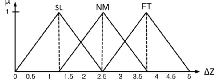
Fig. 2 and Fig. 3 depicted the membership function (MFs) in which H, N, C, NE, NO, PO, SL, NM and FT represent the fuzzy sets (Hot, Normal, Cool, Negative, Normal, Positive, Slow, Normal and Fast respectively) associated to each input and output variable, where the universe of discourse is normalized into e is –2o
C to +2oC, e is –2oC to +2oC, and Z are 0 to 5 Vdc according to the thermal comfort and voltage from data-acquisition card range. The MFs are defined by triangular functions for each variable involved due to the fact give a good controller performance and easy to handle [16 - 17].
µ
µ
Δ
e
e
H N C NE NO PO
1 1
-2 -1 0 1 2 -2 -1 0 1 2
Fig. 2 Membership function of the input variables eand e
µ
Δ
Z
SL
3.5
NM FT
1
0 0.5 1 1.5 2 2.5 3 4 4.5 5
Fig. 3 Membership function of the output variable Z
The rule set of FLC will be three by three, containing nine rules, which governing the input-output relationship of the FLC and this adopts the Mamdani-style inference engine [15], and the centroid method to realize defuzzification method gives a stable steady-state result [18], yield superior results and less computational complexity [19] and the method should work in any situation [15] is used. The rule set is shown in Table 1.
TABLE 1 FUZZY RULE SET
Z
e
H N C
e
NE SL SL SL
NO SL SL SL
PO FT NM SL
III. AIR CONDITIONING SYSTEM PERFORMANCE The coefficient of performance (COP) is commonly used to express the efficiency of an air-conditioning system. The main purpose of AC system is used to remove heat from the evaporator (Qe) and the energy required at the compressor (Wcom) to accomplish the refrigeration effect. Thus, the COP is expressed as:
) (
) ( COP
1 2
4 1
h h
h h W
Q
com e
(1)
where h1, h2 (kJ/kg) are the enthalpy at the compressor inlet
and outlet respectively, h4 (kJ/kg) is the enthalpy at the
evaporator inlet, Qe (kJ/kg) is the refrigerating effect, Wcom
(kJ/kg) is the compression work.
The energy consumption is the power (P) multiplied with time operation (t) of the split unit AC system. Whereas the energy saving is calculated based on the difference between energy consumed with the existing system split unit AC system and energy consumed by variable-speed drive using FLC. The equation is given as:
kWh
t P Energy
kW PF V I
P ( )
1000
(2)
100 AC
Split Existing
AC) Split (FLC -AC) Split (Existing saving
Energy (3)
where I is the current (Ampere), V is voltage (Volts), and PF is power factor.
IV. EXPERIMENTAL SETUP
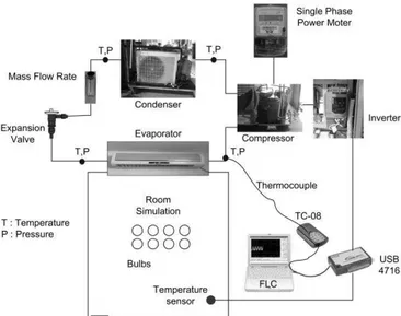
The schematic diagram of the experimental rig as is shown in Fig. 4. The temperature and pressure of the split unit AC system and insulated room were measured by thermocouple sensors (K Type) and pressure gauges (Bourdon tube gauges). The refrigerant flow (R-22) is measured by mass flow rate and located before entering the expansion valve. The energy consumption of the split unit AC system is measured by a power meter. The VSC system consists of an ICs temperature sensor (LM35DZ) was placed in the insulated room and FLC installed into the computer, an inverter (Optidrive E2 Single Phase Input and Output) and split unit AC system (700 W hermetically sealed rotary compressor type). Data from the split unit AC system and insulated room were collected using the USB TC-08 thermocouple data logger and USB-4716. However, pressure, mass flow and energy consumption was directly reading on the instruments.
Fig. 4 Schematic diagram of the experimental rig
The insulated room temperature is monitored by temperature sensors, which emitted the electrical signal to be supplied to the controller and computer. The output signal which is a function of the error between temperature setting and room temperature is then produced to vary the compressor speed. The frequency supplied to the motor is directly proportional to the control signal. By varying frequency of electricity supplied to the inverter, the compressor speed can be varied depending on the temperature monitored by the sensors. This means that the speed of compressor is directly proportional to the frequency of electricity supplied to the motor.
The experiment was conducted on the constant speed compressor system. This is to analyze the performance running under one-fixed compressor speed without any capacity control. The compressor tests with different frequency setting, which is a requirement to study on VSC systems (15, 20, 25, 30, 35, 40, 45, and 50 Hz). Furthermore, the systems were conducted on existing split unit AC system running with thermostat and VSC using FLC to analyze the actual working performance, energy
consumption and potential energy saving. The experiments were performed for one hour and were conducted in temperature setting 23 and 24oC and internal heat loads of 1000 W condition.
V. RESULTS AND ANALYSIS A. Constant Speed Performance
A number of experiments on the variable-speed system have been conducted at different frequencies setting from 15 to 50 Hz. The effect of various frequencies of the room temperature and energy consumption at steady-state condition during a test period is shown in Fig. 5. When the motor frequencies reduced the room temperature will decrease due to the refrigerant flow rate slightly into the compressor and consequently, the energy consumption required at the compressor will also the reduction to cause the evaporator cooling capacity is decreased and vice versa.
Fig. 5 Steady state room temperature and energy consumption at various frequencies
B. Existing System Performance
The thermostat controller is an existing split AC system which is widely used nowadays. The term of the thermostat is meant that the system only allows two conditions operation either compressor motor is on or off.
Fig. 6 shows the room temperature at various temperature settings. Initially, the motor compressor turns on the motor at the maximum speeds of 50 Hz. When the room temperature has reached the temperature setting, the compressor turns off, the process will occur during the temperature setting is achieved. In the thermostat controller mode, the motor turns off when the room temperature at the upper limit setting temperature, and this led to discomfort in the room.
Fig. 6 Room temperature responses with thermostat 0.20 0.30 0.40 0.50 0.60 0.70 0.80
12 17 22 27 32
15 20 25 30 35 40 45 50
E
n
e
rgy
C
on
su
m
p
ti
on
(kWh
)
Roo
m
Te
m
p
e
ra
tu
re
(
oC)
Frequency (Hz) Room Temperature (°C) Energy (kWh)
18.0 20.0 22.0 24.0 26.0 28.0 30.0 32.0 34.0
0 10 20 30 40 50 60
Ro
o
m
Te
m
p
erature
(
o
C)
The disadvantage of the existing split unit AC system where the room temperature in accordance with the temperature setting is not accurate. This is due to the position of temperature sensor of the existing split unit AC system which is located inside the evaporator. Eventually, it makes the sensor to sense different temperature than the actual temperature inside the room and take longer time for the compressor motor to turn back on.
The COP was calculated using equation (1). The results show that the average actual COP of 2.76 for internal heat loads 1000 W. The value of the actual COP represents the motor run at the maximum speeds of 50 Hz. When the motor is off, the actual COP is zero due to the compressor is not working.
C. Variable Speed with FLC Performance
Fig. 7 shows the temperature responses at various temperatures setting using FLC. The inverter was used to enable the compressor motor to run at the variable speeds. In order to let the motor automatically runs at the different speeds to achieve the setpoint temperature, FLC is used. Initially, the compressor motor runs at the maximum speeds of 50 Hz and will decrease when the room temperature reached at the setpoint temperature. The controller minimizes the error between the room and setpoint temperature. Besides that different setpoint temperature effects of the motor speed and room temperature in terms of time taken to reach the required temperature. After around three to six minutes, the room temperature has reached at the setpoint temperature, furthermore, the FLC will control the motor at the slow speeds to maintain the room temperature, and its consequences use less energy.
Fig. 7 Room temperature responses with FLC
The COP was calculated using equation (1). The average value of the actual COP is found to be 3.07 for all temperature settings. The higher of the value of the actual COP is the slower the compressor speed. A Small COP at the higher frequency is mostly due to higher compressor power consumption and vice versa. When the actual COP increases, the compressor speed and power consumption decreases.
D. Energy Analysis
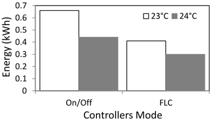
Fig. 8 and Fig. 9 shows the energy consumption and energy saving between the existing split AC system in relation VSD, using FLC. The figures show that energy consumption at different temperature setting and internal heat load of 1000 W. The energy consumption is improved
with increasing the temperature setting. For one hour period continuously running of the experiment, energy saving achieved at internal heat loads 1000 W and various temperature settings of 23 and 24°C are estimated to be between 31.82 to 37.9%.
VI. CONCLUSION
A series of experiments were conducted to study the VSC application on the impact of various frequencies from 15 to 50 Hz. The energy consumption and cooling capacity of the system will affect the temperature, speed depending on the frequency of the motor. The application of VSC in split unit AC systems offer higher-energy saving with better energy-efficiency. The higher frequency at higher thermal load (and vice versa) for the inverter-driven compressors motor to control room temperature will increase the efficiency of the system with better thermal comfort. FLC offers higher-energy saving with better control system, as compared to the existed thermostat controller.
Fig. 8 Energy consumption comparison between existing split unit AC system with VSD using FLC
Fig. 9 Energy saving comparison between existing split unit AC system with VSD using FLC
REFERENCES
[1] H. Nasution, “Energy saving of an air conditioning system using PID
and fuzzy logic controllers,” Ph.D. thesis, Faculty of Mechanical Engineering, Universiti Teknologi Malysia, Malaysia, 2006.
[2] H. Nasution, H. Jamaluddin and J. M. Syeriff, “Energy Analysis for
Air Conditioning System using Fuzzy Logic Controller,” Telkomnika,
vol. 9, no. 1, pp. 139-150, April. 2011.
[3] N. Z. Abidin, “Retrofitting of compressor motor in air conditioning
systems for energy saving,” M.S. thesis, Faculty of Mechanical Engineering, Universiti Teknologi Malaysia, Malaysia, 1995. [4] Y. C. Park, Y. C. Kim and M. K. Min, “Perfomance Analysis on a
Multi-Type Inverter Air Conditioner,” Energy Conversion & Management, vol. 42, no. 13, pp. 1607-1621, September. 2001. 22.0
23.0 24.0 25.0 26.0 27.0 28.0 29.0
0 10 20 30 40 50 60
R
o
o
m
Tem
p
er
a
tu
re
(
o
C)
Time (minute)
1000 W at T = 23 C Setpoint, T = 23 C 1000 W at T = 24 C Setpoint, T = 24 C
0 0.1 0.2 0.3 0.4 0.5 0.6 0.7
On/Off FLC
En
er
gy
(
k
Wh
)
Controllers Mode
23°C 24°C
0 0.1 0.2 0.3 0.4 0.5 0.6 0.7
On/Off FLC
En
er
gy
(
k
Wh)
Controllers Mode
[5] J. Zhang, G. Qin, B. Xu, H. Hu, and Z. Chen, “Study on Automotive Air Conditioner Control System Based on Incremental-PID,”
Advanced Material Research, vol. 129, pp. 17-22, 2010.
[6] H. Khayyam, A.Z. Kouzani, E. J. Hu and S. Nahavandi, “Coordinated
Energy Management of Vehicle Air Conditioning System,” Applied
Thermal Engineering, vol. 31, no. 5, pp. 750-764, April. 2011.
[7] H. Khayyam, A. Z. Kouzani and E. J. Hu, “Reducing energy
consumption of vehicle air conditioning system by an energy
management system,” in Proc. IEEE The 4th International Green
Energy Conference, Beijing, China, 2009.
[8] J. M. Sousa, R. Babuska and H. B. Verbruggen, “Fuzzy Predictive
Control Applied to Air-Conditioning System,” Control Engineering Practice, vol. 5, no. 10, pp. 1395-1406, October. 1997.
[9] F. Calvino, M. Gennusa, G. Roizzo and G. Scaccianoce, The Control of Indoor Thermal Comfort Conditions: Introducing a Fuzzy Adaptive
Controller,” Energy and Buildings, vol. 36, no. 2, pp. 97-102,
February. 2004.
[10] R. Thompson and A. Dexter, “A Fuzzy Decision-Making Approach to Temperature Control in Air-Conditioning Systems,” Control Engineering Practice, vol. 13, no. 6, pp. 689-698, June. 2005.
[11] Y. Farzaneh and A. A. Tootoonchi, “Controlling Automobile Thermal
Comfort using Optimized Fuzzy Controller,” Applied Thermal Engineering, vol. 28, no. 14-15, pp. 1906-1917, October. 2008. [12] H. Khayyam, S. Nahavandi, H. Eric, A. Kouzani, A. Chonka, J.
Abawajy, V. Marano and D. Sam, “Intelligent Energy Management Control of Vehicle Air Conditioning via Look-Ahead System,”
Applied Thermal Engineering, vol. 31, no. 16, pp. 3147-3160, November. 2011.
[13] H. Nasution and M. N. W. Hassan, “Potential Electricity Savings by
Variable Speed Control of Compressor for Air Conditioning
Systems,” Clean Technologies and Environmental Policy, vol. 8, pp.
105-111, March. 2006.
[14] L. I. Davis, T. F. Sieja, R. W. Matteson, G. A. Dage and R. Ames,
“Fuzzy logic for vehicle climate control, in: Fuzzy Systems,” in Proc.
IEEE World Congress on Computational Intelligence, Orlando, USA, 1994, pp. 530-534.
[15] K. M. Pasino and S. Yurkovich Fuzzy Control. United State of America: Addison Wesley, 1998.
[16] A. I. Dounis and D. E. Manolakis, “Design of A Fuzzy System for
Living Space Thermal Comfort Regulation,” Applied Energy, vol. 69,
no. 2, pp. 119-144, June. 2001.
[17] A. Bagis, “Determining Fuzzy Membership Functions With Tabu
Search-An Application to Control,” Fuzzy Sets and Systems, vol. 139, no. 1, pp. 209-225, October. 2003.
[18] D. Kolokotsa, D. Tsiavos, G. S. Stavrakakis, K. Kalaitzakis and E. Antonidakis, “Advanced Fuzzy Logic Controllers Design and Evaluation for Buildings’ Occupants Thermal Visual Comfort and Indoor Air Quality Satisfaction,” Energy and Buildings, vol. 33, no. 6, pp. 531-543, July. 2001.
[19] I. Eker and Y.Torun, Fuzzy Logic Control to be Conventional
Method,” Energy Conversion & Management, vol. 47, no. 4, pp.