International Journal of Electronics and Computer Science Engineering
18
Available Online at www
.
ijecse
.
org
ISSN- 2277-1956
ISSN 2277-1956
/V2N1-18-22
Multi-focus Image Fusion Using De-noising and Sharpness
Criterion
Sukhdip Kaur
,
Kamaljit Kaur
1. M.Tech (research student), Guru Nanak Dev Engg. College, Ludhiana.2. Assistant professor Guru Nanak Dev Engg. College, Ludhiana.
[email protected], [email protected]
Abstract— the concept of multi-focus image fusion is used to combine multiple images with different objects in focus to obtain all the objects in focus and for better information in a scene. But the challenge is to how evaluate the information of the input images with better quality of image. In order to provide solution of this problem, a new criterion is proposed to give better quality of image using PCA, by de-noising and bilateral gradient based sharpness criterion that is evaluated using the gradient information of the images. Then the proposed method is further exploited to perform weighted aggregation of multi-focus images. The experimental results show that the proposed method is better than the other method in terms of quality matrices like Mutual information, spatial frequency and Average difference.
Keywords — Image fusion, Gradient Sharpness, PCA.
I. INTRODUCTION
The images are the real description of objects. When the images are taken from camera there are some limitations of a camera system. One of which is the limitation of depth of focus. Due to this an image cannot be captured in a way that all of its objects are well focused. Only the objects of the image with in the depth of field of camera are focused and the remaining will be blurred. To get an image well focused everywhere, we need to fuse the images taken from the same view point with different focus settings. The term image fusion is used for practical methods of merging images from various sensors to provide a composite image which could be used to better identify natural and manmade objects. In the recent research works the researchers have used various techniques for multi-resolution image fusion. Multi-focus problem is when the objects of the image cannot be in focus at the same time due to the limited depth-of-focus of optical lenses in devices. The aim of multi-focus images fusion is to achieve all objects in focus by combining a few of images of different focus and to keep details as more possible. The key challenge of multi-focus image fusion is how to evaluate the blurriness of each image and then select information from the most informative (sharp) image.
II. PROBLEM FORMULATION
For an image fusion, there is a simple and effective method that is to perform a simple normalized aggregation of the images, which can be mathematically given by
S(r, c) =
∑
( , )
(1)
where N is the set of images X1, X2…Xn and S(r, c) is the fused image [1]. But the problem with the above simple normalized aggregation of images is that it treats all the information content as same within the images .And due to this, the important image regions, which yield more detailed information (edge or high-frequency) and are more informative, are treated same and not differently than unimportant regions. To overcome this problem, a normalized weighted aggregation approach to image fusion can be used. It can be mathematically expressed as
F(r, c) = ∑ ( , ) ( , ) !"#
∑!"# ( , )
(2)
III. EXISTING SHARPNESS CRITERIONS
In this section the existing sharpness criterions have been provided. The amount of high-frequency information (corresponding to edge information in images) is usually used as the basis to measure the degree of image's blur, because the degree of de-focus varies inversely with the amount of high spatial frequency energy present in the spatial frequency spectrum [2]. So we can say, the image that will be well focused, that image will be sharper and will be having higher frequency content than those that are blurred. In the following analysis, denote X(r, c) be the intensity value at the position (r, c) of the image X.
A. Energy of image gradient
For an M×N block of the image, it is measured as [3].
%&'=∑ ∑ ( + ) (3)
where Xr and Xc represent image gradients at the row and column directions, respectively. They are usually defined as
Xr = X(r+1, c) −X(r, c)
and Xc= X(r, c+1) −X(r, c).
B. Tenenbaum
For an M×N block of the image, it is measured as [3]
%) ' = ∑ ∑ (∇ ( , )) (4)
where ∇ ( , ) = + +
in which Xr and Xc are gradients (obtained using Sobel operators) along the row and column directions, respectively.
C. Phase coherence model
It is consistent to the perceptual significance of the image, and as in [4], it can be determined at a particular position (r, c) as
%,-.( , )= ∑ |ℎ( , , 1) sin(1)) + ℎ( , , 1) cos(1)) |6
+ +4(∑ (ℎ( , , 1) sin(1) ℎ( , , 1) cos(1))6 )) + ∑ 8(ℎ( , , 1) cos(1)) − ℎ( , , 1) sin(1)) :6
(5)
where
h (r, c, θ) = ∑ ;( , ,6)|< ( , ,6)∆> ( , ,6)|∑ < ( , ,6)?@ and (6)
∆A ( , , 1 ) = cos (A ( , , 1) − ABBBB( , , 1))-|sin(A ( , , 1) − ABBBB( , , 1)| (7)
in which W represents the frequency spread weighting factor, An and φn represent the amplitude and phase at the wavelet scale n, respectively, ABBBB represents the weighted mean phase, ξ is a small constant used to avoid the division by zero. All of these parameters are as same as that used in [5].
D. Bilateral gradient based sharpness criterion
This approach exploits a bilateral sharpness criterion to adaptively perform image fusion by selecting most informative (sharp) information from the input images [1]. It is given by
%CD- = EF( , )GH( , ) (8)
where α and β are to adjust the contribution.
IV. PROPOSED ALGORITHM
1) Read the two gray with different focus.
2) Compute the size of images and calculate the number of pixels in the images.
Multi-focus Image Fusion Using De-noi
ISSN 2277-1956
/V2N1-18-22
4) Set parameters l, m and n to adju these parameters have been set. F globally optimal.
5) Calculate the gradient covariance
CM=I ∑ J (, ∑ J ,
∑ J , , ∑ J
Where Xr (r, c) and Xc (r, c) repre 6) Decompose the gradient covarianc
CM=VDK)=L1 L2 OP0 P R O0 L)
L)R Where V represent 2×2 matrix wh diagonal elements are eignvalue respectively and T is the transpose 7) The geometrical structure at a pix covariance matrix [7]. Let ST to m
ST =P -P
8) Let PH to measure phase coheren
PH = -cos (θ (r, c)- 1(r,
Where
θ
(r, c) is the phase inform largest eigenvaluesP
defined as 9) Calculate the covariance matrix covariance vector would contain t Eigen vectors of the covariance m values by dividing each element w 10) Fuse the images using the steps 7,Proposed method = √UV+%W GXYPCA+
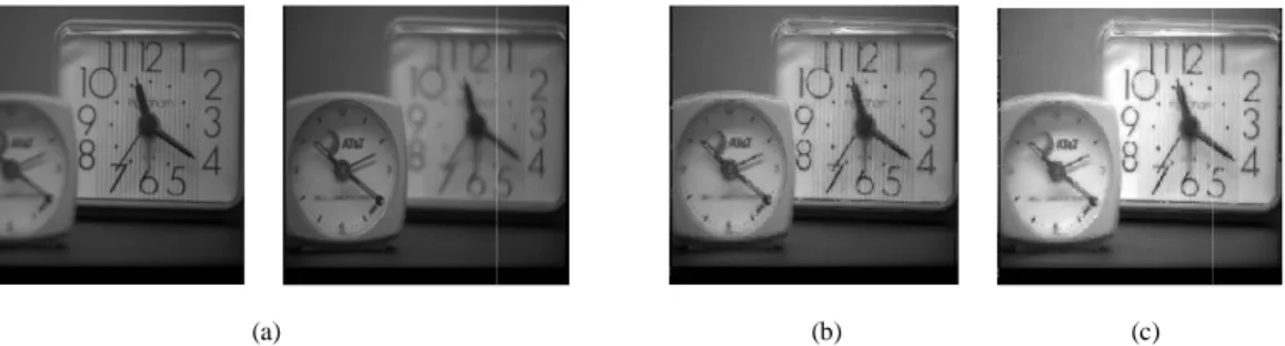
(a)
Fig. 1.
oising and Sharpness Criterion
djust the contribution of the criterions used in the algor . For different images l, m and n can be adjusted accord
ce matrix CM for an image X(r, c) [6] ,that is expressed
,
, Z (9)
present image's gradient at the row and column direction ance matrix of the input image A and input image B
R (10)
whose column vectors are eigenvectors v1 and v2. D is lues
λ and λ
where (λ \ λ
that correspon ose.pixel in an image can be described by the eigenvalues λ
o measure strength of the image’s gradient for input imag
(11)
rence of the image’s gradient of input images, given as
(r, c) (12)
ormation at position (r, c) determined by the principal as in (10) and
θB
(r, c) is the average of phases of the neighix taking two column vectors from input image. The n the variance of each column vector with itself. Now ca e matrix [8]. After that normalize the column vector co t with mean of the Eigen vector, to obtain the componen 7, 8 and 9 jointly.
+√%WY G]E (13)
(b)
(c)
. Three sets of test images: (a) Clock, (b) Plane and (c) Boxes.
20
orithm. To get good performance, ordingly. The setting might not be
sed below
ions of the image.
is a 2×2 diagonal matrices whose onds to eigenvectors v1 and v2
es λ1 and λ2 of the above gradient ages, given as
al eigenvector v1 associated with ighbouring positions.
he diagonal elements of the 2x2 calculate the Eigen values and the corresponding to the larger Eigen
(a)
Fig. 2. A comparison of fused images (Clock) using
(a)
Fig. 3. A comparison of fused images (Plane) using
(a)
Fig. 4. A comparison of fused images (Box) using d
Some experiments have been performe weighting scheme of (2) to perform imag with different focus levels: 256×256 Clock fused images is presented in Figs. 2–4, r yield better image quality than that of the fused image that are: i) mutual informatio larger metrics values indicate better image The objective performance comparisons always outperforms than other convention
Meth
Bilatera
(b) (c)
ing two methods: (a) two source images; (b) and (c) are results obtaine proposed method in (13)
(b) (c)
ing two methods: (a) two source images; (b) and (c) are results obtaine proposed method in (13)
(b) (c)
g different methods: (a) two source images; (b) and (c) are results obta by proposed method in (13)
V. EXPERIMENTAL RESULTS
med to compare the performance of the method (13) w age fusion. The first experiment is to conduct image fu ock, 256×256 Plane, and 256×256 Boxes, as shown in F , respectively. One can see that the fused images obtai he other approach. Three metrics have been used to eva tion metric [9] ii) spatial frequency metric [10] and iii) age quality for (i) and (ii), But lower value for (iii) avera ns are presented in Tables 1, 2 and 3, where one can ional criterion by producing the better objective performa
TABLE I. MUTUAL INFORMATION PERFORMANCE
thod IMAGES
Clock Plane Box
eral 8.49 7.66 7.55
ined using criterions defined in (8) and by
ined using criterions defined in (8) and by
btained using criterions defined in (8) and
22
Multi-focus Image Fusion Using De-noising and Sharpness CriterionISSN 2277-1956
/V2N1-18-22
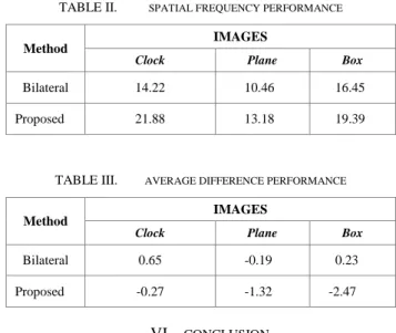
TABLE II. SPATIAL FREQUENCY PERFORMANCE
Method IMAGES
Clock Plane Box
Bilateral 14.22 10.46 16.45
Proposed 21.88 13.18 19.39
TABLE III. AVERAGE DIFFERENCE PERFORMANCE
Method IMAGES
Clock Plane Box
Bilateral 0.65 -0.19 0.23
Proposed -0.27 -1.32 -2.47
VI. CONCLUSION
A multi-focus image fusion approach using a new sharpness criterion that depends on statistics of image's gradient information with de-noising and PCA is proposed in this paper. The noise has been removed using the adaptive filtering approach. The proposed sharpness criterion outperforms bilateral sharpness criterions, as verified in our extensive experiments using three sets of test images under three objective metrics. There are a few directions for future research. First, the proposed approach is conducted using new fusion rules in order to provide better quality and more information of image fusion. Second, the proposed method can be used for more than two input images.
REFERENCES
[1] Jing Tian , Li Chen , Lihong Ma and Weiyu Yu, “Multi-focus image fusion using a bilateral gradient-based sharpness criterion,” Optics Communications ,School of Computer Science and Technology, Wuhan University of Science and Technology, 430081, PR China. 284 (2011) ,pp. 80–87.
[2] V. Aslantas, R. Kurban, Optics Communications 282 (Aug. 2009) 3231.
[3] W. Huang, Z. Jing, “Evaluation of focus measures in multi-focus image fusion” Pattern recognition Letters 28 (Apr.2007) pp. 493.
[4] Alexander Wong and William Bishop, “Efficient least squares fusion of MRI and CT images using a phase congruency model,” Department of Electrical and Computer Engineering, University of Waterloo, Waterloo, Ontario, N2L 3G1 Canada, Pattern Recognition Letters 29 (2008) ,pp. 173–180.
[5] P. Kovesi, Videre: A Journal of Computer Vision Research 1 (1999) 2.
[6] Amit Agrawal, Ramesh Raskar and Rama Chellappa, “Edge Suppression by Gradient Field Transformation using Cross-Projection Tensors,” Proc. IEEE Int. Conf. on Computer Vision and Pattern Recognition, 2006, p. 2301.
[7] C.-Y. Wee and R. Paramesran, “Measure of image sharpness using eigenvalues,” Information Sciences, vol. 177, pp. 2533-2552, 2007.
[8] Shivsubramani Krishnamoorthy and K P Soman, “Implementation and Comparative Study of Image Fusion Algorithms,” Centre for Excellence in Computational Engineering,Amrita University, Coimbatore, India, International Journal of Computer Applications (0975 – 8887) Volume 9– No.2, November 2010.
[9] Jahan B. Ghasemi and Ehsan Zolfonoun, “A new variables selection method based on mutual information maximization by replacing collinear variables for nonlinear qantitative structure property relationship models,” Chemistry Department, Faculty of Sciences, K.N. Toosi University of Technology, Tehran, Iran, Vol. 33, No. 5 ,pp.1527-1535.
[10] Shutao li,James T. Kwok and Yaonan wang, , “Combination of images with diverse focuses using spatial frequency”, Information fusion 2, 2001, pp. 169-176.