22
Experimental Determination of Effect of Variable Resistance on Lead
Zirconate Titanate (PZT-5A4E) under various Thermal
and Frequency Conditions
Hassan Elahi1; RiffatAsim Pasha2; Asif Israr1; M. Zubair Khan1
1
Institute of Space Technology, Islamabad, Pakistan.
2
University of Engineering and Technology, Taxila, Punjab, Pakistan.
[email protected], [email protected], [email protected], [email protected]
Date Received: September 7, 2014; November 26, 2014
Abstract: A specially designed apparatus and circuit working on the principle of inverse piezoelectricity due to the effect of polarization was used to find the relationship between resistance and peak to peak voltage of Lead Zirconate Titanate (PZT-5A4E) by shocking it at variable frequencies and at variable resistances under various thermal conditions within Curie temperature limit using equivalent circuit method. It was found that by increasing temperature, peak to peak voltage increases and similarly by increasing frequency, peak to peak voltage decreases and with the increase in resistance peak to peak voltage decreases.
Keywords: PZT5A4E; Resistance; Electromechanical Interaction; Frequency; Thermal Conditions.
I. INTRODUCTION
Piezoelectric materials have a crystalline structure having the ability to convert mechanical strain energy into electrical charge and on the other hand applied electrical potential into mechanical strain. This characteristic provides these materials the ability to absorb mechanical energy from their surroundings, normally vibration, and transform it into electrical energy that can be used to power other devices. Piezoelectric materials can be considered to mass of minute crystallites (domains). The macroscopic behaviour of the crystal differs from that of individual crystallites, due to orientation of such crystallites [1]. The technique to convert mechanical input to electric output by the help of piezoelectric vibrator was developed in 1947 by Bond, W.L [2].Giannakopoulos, A. and S. Suresh determined that the electric voltage generated by piezoelectric material depends on its boundary conditions as well as on its electrical conductivity [3]. Jiang, C. and Y. Cheung proposed a three phase model for piezoelectric material [4]. Magneto-electric voltage increases with increase in temperature [5].Kim, C.-S., S.-K. Kim, and S.Y. Lee determined the piezoelectric and dielectric values of newly doped piezoelectric materials at different calcination and sintering temperatures [6]. Piazza, G.,
et al. experimentally showed that piezoelectric material has central frequency on which voltage is tunable and it depends on a critical value at which material resonates [7]. Zhang, S., et al. developed piezoelectric material for high power applications and high temperature applications [8]. Moure, A., A. Castro, and L. Pardo showed trends and behavior of a piezoelectric material as a ceramic at different temperatures [9]. Okayasu, M., K. Sato, and Y. Kusaba, experimentally analyzed the domains of Lead ZirconateTitanate during loading and unloading conditions [10].
II. MATERIAL
23
Table I Description of specimen (PZT-5A4E Single Layer Disks)
Composition Trade (Dimension) Part No
Diameter Thickness
Lead ZirconateTitanate PiezoSystems Inc. 12.7mm 0.191mm T107-A4E-273
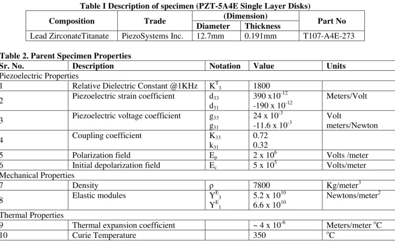
Table 2. Parent Specimen Properties
Sr. No. Description Notation Value Units
Piezoelectric Properties
1 Relative Dielectric Constant @1KHz KT3 1800
2 Piezoelectric strain coefficient d33 d31
390 x10-12 -190 x 10-12
Meters/Volt
3 Piezoelectric voltage coefficient g33
g31
24 x 10-3 -11.6 x 10⁻³
Volt
meters/Newton 4 Coupling coefficient K33
k31
0.72 0.32 5 Polarization field Ep 2 x 10
6
Volts /meter 6 Initial depolarization field Ec 5 x 10
5
Volts/meter Mechanical Properties
7 Density ρ 7800 Kg/meter3
8 Elastic modules Y
E 3
YE1
5.2 x 10¹⁰ 6.6 x 10¹⁰
Newtons/meter2
Thermal Properties
9 Thermal expansion coefficient ~ 4 x 10⁻⁶ Meters/meter oC
10 Curie Temperature 350 oC
III. EXPERIMENTAL SETUP
Experimental setup was designed in such a way that load cell is fixed on a base of mild steel iron sheet and piezoelectric ring shaped specimen with nut and bolt on
a load cell in such a way that it’s lower and upper both
sides face copper electrodes acting as anode and cathode. Mica sheet was utilized for electrical and thermal insulation between electrodes and load cell. Heat filament element was utilized in the circuit for on spot heating and temperature was observed with the
help of temperature gun. Lead ZirconateTitanate (PZT-5A4E) specimen was then thermally shocked with the help of function generator at various frequencies and resistances which were varied using decade resistor box. The response is analysed on digital oscilloscope at different temperatures. Experimental setup and overall circuit diagram are shown in Fig. 1 and Fig. 2 respectively.
24
Fig.2 Overall circuit diagram for the experimental setup
IV. RESULTS AND DISCUSSIONS
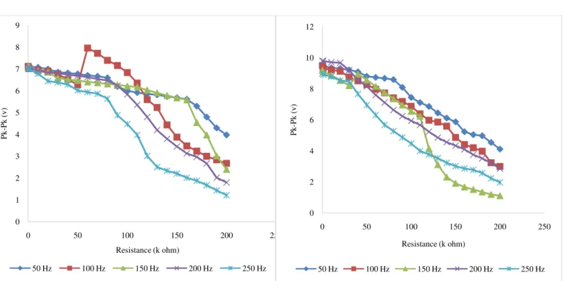
During the experimentation it is observed that by increasing temperature, the peak to peak voltage increases but by increasing frequency the output peak to peak voltage decreases. For maximum results optimization has to be done by increasing temperature,
decreasing resistance, and decreasing frequency. Experimentation is performed at temperatures varying from 20 °C to 200 °C temperature, resistance varies from 0 KOhm to 200 KOhm, and frequency ranges from 20 Hz to 200Hz. The results obtained are shown in the graphs below:
Fig. 3 Resistance vs. Pk-Pk voltage at 50 Hz Frequency & Variable Temperature
Fig. 4 Resistance vs. Pk-Pk voltage at 100 Hz Frequency & Variable Temperature
0 1 2 3 4 5 6 7 8 9 10
0 50 100 150 200 250
Pk
-P
k
(
v
)
Resistance (K Ohm)
20C 60C 100C 180C
0 1 2 3 4 5 6 7 8 9 10
0 50 100 150 200 250
Pk
-P
k
(
v
)
Resistance (K Ohm)
25
Fig. 5 Resistance vs. Pk-Pk voltage at 150 Hz Frequency & Variable Temperature
Fig. 6 Resistance vs. Pk-Pk Voltage at variable temperature and 250 hertz frequency
Fig. 7 Resistance vs. Pk-Pk Voltage at variable Frequency and 20 °C Temperature
Fig. 8 Resistance vs. Pk-Pk Voltage at variable Frequency and 60 °CTemperature
0 1 2 3 4 5 6 7 8 9 10
0 50 100 150 200 250
Pk
-P
k
(
v
)
Resistance (K Ohm)
20C 60C 100C 180C
0 1 2 3 4 5 6 7 8 9 10
0 50 100 150 200 250
Pk
-P
k
(
v
)
Resistance (k ohm)
20C 60C 100C 180C
0 0.5 1 1.5 2 2.5 3 3.5 4 4.5 5
0 50 100 150 200 250
Pk
-P
k
(
v
)
Resistance (K Ohm)
50 Hz 100 Hz 150 Hz 200 Hz 250 Hz
0 1 2 3 4 5 6 7
0 50 100 150 200 250
Pk
-P
k
(
v
)
Resistance (K Ohm)
26
Fig. 9 Resistance vs. Pk-Pk Voltage at variable Frequency and 100 °CTemperature
Fig. 10 Resistance vs. Pk-Pk Voltage at variable Frequency and 180 °CTemperature
V. CONCLUSIONS
Following conclusions can be drawn from this research work:
1. By increasing temperature up to Curie temperature the peak to peak voltage of Lead ZirconateTitanate (PZT-5A4E) increases as a linear function.
2. By increasing frequency peak to peak voltage decreases linearly.
3. For best performance and maximum peak to peak voltage use PZT at 180°C temperature, 0 Ohm resistance, and 0 Hz frequency because dipolar motion of its ions is maximum at these conditions. 4. Negative linear behaviour is observed between
frequency and peak to peak voltage as well as for resistance and peak to peak voltage.
5. At high resistance and frequency the motion of ions restricted so rate of polarization decreases which result in lowering of peak to peak voltage. So it is highly applicable to use Lead ZirconateTitanate (PZT-5A4E) at high temperature, low resistance and low frequency.
REFERENCES:
[1] Liu, C., Foundation of MEMS. Electrical and computer Department University of Illionis at
Urbana-Champaign Pearson Education International, 2006.
[2] Bond, W.L., PIEZOELECTRIC VIBRATOS. 1947, Google Patents.
[3] Giannakopoulos, A. and S. Suresh, Theory of indentation of piezoelectric materials. Acta materialia, 1999. 47(7): p. 2153-2164.
[4] Jiang, C. and Y. Cheung, An exact solution for the three-phase piezoelectric cylinder model under antiplane shear and its applications to piezoelectric composites. International journal of solids and structures, 2001. 38(28): p. 4777-4796.
[5] Ryu, J., et al., Piezoelectric and magnetoelectric properties of lead zirconate titanate/Ni-ferrite particulate composites.
Journal of Electroceramics, 2001. 7(1): p. 17-24.
[6] Kim, C.-S., S.-K. Kim, and S.Y. Lee,
Piezoelectric properties of new PZT–PMWSN ceramic. Materials Letters, 2003. 57(15): p. 2233-2237.
[7] Piazza, G., et al., Voltage-tunable piezoelectrically-transduced single-crystal silicon micromechanical resonators. Sensors
0 1 2 3 4 5 6 7 8 9
0 50 100 150 200 250
Pk
-P
k
(
v
)
Resistance (k ohm)
50 Hz 100 Hz 150 Hz 200 Hz 250 Hz
0 2 4 6 8 10 12
0 50 100 150 200 250
Pk
-P
k
(
v
)
Resistance (k ohm)
27
and Actuators A: Physical, 2004. 111(1): p. 71-78.
[8] Zhang, S., et al., Piezoelectric materials for high power, high temperature applications.
Materials Letters, 2005. 59(27): p. 3471-3475. [9] Moure, A., A. Castro, and L. Pardo,
Aurivillius-type ceramics, a class of high temperature piezoelectric materials: Drawbacks,
advantages and trends. Progress in Solid State Chemistry, 2009. 37(1): p. 15-39.