A Distributed Method to Localization for Mobile
Sensor Networks based on the convex hull
Yassine SABRI
STIC LaboratoryChouaib Doukkali University, B.P: 20 El Jadida MOROCCO
Najib EL KAMOUN
STIC LaboratoryChouaib Doukkali University, B.P: 20 El Jadida MOROCCO
Abstract— There has been recently a trend of exploiting the heterogeneity in WSNs and the mobility of either the sensor nodes or the sink nodes to facilitate data dissemination in WSNs. Recently, there has been much focus on mobile sensor networks, and we have even seen the development of small-profile sensing devices that are able to control their own movement. Although it has been shown that mobility alleviates several issues relating to sensor network coverage and connectivity, many challenges remain. Among these, the need for position estimation is perhaps the most important. Not only is localization required to understand sensor data in a spatial context, but also for navigation, a key feature of mobile sensors. This paper concerns the localization problem in the case where all nodes in the network (anchors and others sensors) are mobile. We propose the technique following the capabilities of nodes. Thus, each node obtains either an exact position or an approximate position with the knowledge of the maximal error born. Also, we adapt the periods where nodes invoke their localization. Simulation results show the performances of our method in term of accuracy and determinate the technique the more adapted related to the network configurations.
Keywords- wireless sensor network (WSN); Mobility; Localization; scalability.
I. INTRODUCTION
A wireless sensor network is composed of a large number of small and inexpensive smart sensors for many monitoring, surveillance and control applications. Each sensor makes its own local observation. All active sensors in the network coordinate to provide a global view of the monitored area. It is anticipated that such a network can be used in unattended environments or hostile physical locations. Applications include habitat monitoring [1][2], infrastructure surveillance [3], target tracking in tactical environments [4], etc. Almost all these applications require sensors to be aware of their physical locations. For example, the physical positions should be reported together with the corresponding observations in wildlife tracking, weather monitoring, location-based authentication, etc [5][6][7]. Location information can also be used to facilitate network functions such as packet routing [8][9] and collaborative signal processing [10], in which the complexity and processing overhead can be substantially reduced. Further, each node can be uniquely identified with its position, thus exempting the difficulty of assigning a unique ID before deployment [11]. However, many challenges exist in designing effective and efficient sensor self-positioning schemes for sensor networks. First, a localization algorithm
must scale well to large sensor networks. Further, the location discovery scheme should not aggravate the communication and computation overheads of the network, since low-cost sensors have limited resource budgets such as battery supply, CPU, memory, etc. What’s more, the localization scheme should not raise the construction cost of sensor nodes. Finally, the positioning scheme should be robust enough to provide high precision even under noisy environments.
This paper deals with the problem of localization in wireless sensor networks when sensors are mobile. There are three scenarios of mobility: sensors and anchors are mobile; sensors are mobile and anchors are static; sensors are static and anchors are mobile. For the last case, some methods have been proposed [12], [13]. In these methods, mobile anchors can be robots, humains, or other, equipped GPS which are used in order to locate others static sensors. In this paper, we present a new method to resolve the localization problem in the complex scenario where nodes and anchors are mobile. However, this method can be used for the two others cases of mobility. Three schemes are proposed following the capabilities of sensors. Sensors can be equipped with techniques like ToA/TdoA (Time of arrival / Time difference of arrival) or RSSI (Received Signal Strength Indicator) allowing computing distance between a pair of neighbor sensors. They may also be equipped with AoA (Angle of arrival) technique allowing computing angle between a pair of neighbor sensors. Finally, sensors may be equipped by none of these techniques. Our method determines an exact position for a sensor when it has at least two anchors in its neighborhood. Otherwise, it gives an approximate position and can compute in this case the generated maximal error. The localization problem with mobile sensors introduces a new problem: in fact, the energy of sensors being weak, each node cannot compute continually its localization in order to maintain accuracy position during its move.
When a node invokes its localization it does not always obtains its exact position: either it obtains an approximate position or it cannot locate itself. To overcome this problem, our method defines the periods when a node has to invoke its location. Finally, through simulations, we analyze performances of our three techniques.
The rest of the paper is organized as follows: In Section 2, we summarize related work on localization algorithms. In Section 3, introduces basic notions for this problem. In Section 4 and 5, we present our new localization algorithm. In Section 6, we evaluate the proposed scheme through comprehensive simulation studies. We conclude the paper in Section 6.
II. RELATED WORK AND BACKGROUND
First, The popular Global Positioning System (GPS) [15] localization system may not be a practical solution for outdoor sensor networks. It is infeasible to install GPS on each sensor due to cost, form factors, power consumption and antenna requirements. Further, GPS requires direct Light-Of-Sight (LoS) communication, which renders it unfeasible for many outdoor application environments. Therefore in the past several years, extensive research has been directed to designing GPS-less location discovery schemes [16], [17], [18], [19], [20], [21], [22], [23], [24], [25], [26], [27], [28], [29], [30], [31], [32], [33], [34], [7], [35], [36] .These positioning algorithms differ in their assumptions on network deployment, device capabilities, node mobility, signal propagation, error requirement, etc. Thus, they can be classified differently.
For example, some methods are designed for static sensor networks, where sensors remain stationary after deployment, while others are for dynamic sensor networks where sensors and beacons are mobile [40]. These localization schemes can also be classified as centralized [37], [33], [39], where all computations are performed by a central point (e.g., the base station), or distributed, where sensors estimate their positions independently of each other. Centralized methods have poor scalability and are thus infeasible for large sensor networks. In this section, we will focus on distributed location discovery schemes for stationary sensor networks, which can be further classified as beacon-based and beacon-less depending on whether or not beacons are used, or classified as range-based and range-free according to the type of knowledge used in position estimation.
The majority of current location detection systems assume the existence of beacons, whose positions are known through GPS receivers or manual configuration. A typical sensor first measures the distances or angles from it to several beacons, and then obtains position estimation through techniques such as triangulation, trilateration, multilateration, etc. Based on the coverage capabilities of beacons, these localization systems can be further classified as systems with long-range beacons or systems with short-range beacons. Systems with long-range base stations have a fixed set of powerful beacons, whose transmission range can cover the entire network. Usually these base stations are manually deployed, are time-synchronized, and are equipped with special instruments such as directional antennas. In systems with shortrange beacons [33], [34], [7], [35], a small number of sensors with known positions are
randomly deployed amongst other ordinary sensors. Some of them rely on transmitting both RF and ultrasound signals at the same time, where the RF is used for time-synchronizing the sender and the receiver.
Range-based localization relies on the availability of point-to-point distance or angle information. The distance/angle can be obtained by measuring Arrival (ToA), Time-Difference-of- Arrival (TDOA), Received-Signal-Strength-Indicator (RSSI), and Angle-of-Arrival (AOA), etc. The range-based localization may produce fine-grained resolution, but have strict requirements on signal measurements and time synchronization. ToA measures the signal arrival times and calculates distances based on transmission times and speeds. GPS [16] is the most popular ToA-based localization system. By precisely synchronizing with a satellite’s clock, GPS computes node position based on signal propagation time. Compared to ToA, TDoA has an advantage as the former’s processing delays and non-LOS propagation can introduce larger errors [38]. Ref. [7] proposes a TDoA based scheme (AHLos) that requires base stations to transmit both ultrasound and RF signals simultaneously.
The RF signal is used for synchronization purposes. A sensor first measures the difference of the arrival times between the two signals, then determines the range to the base station. Finally, multilateration is applied to combine range estimates and generate location data. RSSI computes distance based on transmitted and received power levels, and a radio propagation model. RSSI is mainly used with RF signals [16], but the range estimation can be inaccurate due to multipath fading in outdoor environments [7]. AoA-based methods first measure the angle at which a signal arrives at a base station or a sensor, and then estimates the position using triangulation.
The calculation is quite simple, but AoA techniques require special antenna and may not perform well due to omnidirectional multipath reflections. Further, the signals can be difficult to measure accurately if a sensor is surrounded by scattering objects [12]. To the best of our knowledge, there is no other method, in the open literature that deals with this case. Some papers have been proposed in the case where anchors are mobiles and others sensors are static.
For example, [12], [13] uses robots or humans, which can be considered as anchors, move in the network and help others nodes to obtains their positions. When sensors are mobile, it is not reasonable that each sensor invokes its localization technique in order to locate itself continually, due to constraint of energy. A first work in [14] proposes three methods SFR (Static Fixed Rate), DVM (Dynamic Velocity Monotonic), MADRD (Mobility Aware Dead Reckoning Driven) to determinate periods where a node invokes its localization technique. But, it assumes that a node obtains its exact position when it invokes its localization (e.g. sensors are equipped with GPS). The following sub-sections explain these three methods.
the position of sensors. They proposed techniques: Static Fixed Rate (SFR), dynamic Velocity Monotonic (DVM) and Mobility Aware Dead Reckoning Driven (MADRD). SFR calls a classical localization operation periodically with a fixed time interval. To respond a query from the base station, a sensor sends its position obtained from the last localization. When a sensor remains still or moves fast, in both cases, the reported position suffers a large error. In DVM, localization is called adaptively with the mobility of the sensors. The time interval for the next call for localization is calculated as the time required to traverse the threshold distance (a distance, traversed by the sensor, location estimation assumed to be error prone) with the velocity of the sensor between last two points in the sequence of localization calls. In case of high mobility, a sensor calls localization frequently. If a sensor suddenly moves with very high speed from rest, error in the estimated location becomes very high. In MADRD, the velocity is calculated from the information obtained from last two localized points.
The predictor estimates the position with this velocity and communicates to the query sender. At the localization point, the localized position is reported to the query sender and the distance error is calculated as the distance between the predicted position and reported position.
III. PRELIMINARY
Before In this paper, we focus on mobile sensor network. Moreover, we assume that all the sensors have identical transmission radius
r
. however, it is easy to adapt our method with sensors having different transmission radius. We represent a wireless sensor network as a graph G(V,E) whereV
is the set of n nodes representing sensors and E is the set of m edges representing communication links. If two nodesu
,v
are neighbors, then they are linked and the distance between u andv
is smaller thanr
. We assume also that some anchors have a priori knowledge of their own positions with respect to some global coordinate system (GPS) (black nodes in figures). We consider scenarios where nodes and anchors are mobile.For example, in a military context, soldiers can be equipped with sensors and tanks with anchors. Soldiers use tank positions in order to obtain their positions. Finally, we should take into account functionalities of each sensors: for example, methods like RSSI or ToA/TDoA and AoA described in previous section. A wireless sensor networks is represented as a bidirectional graph G(V,E) where
V
is the set ofn
nodes representing sensors andE
is the set ofm
edges representing communication links. If two nodesV
v
u
,
are neighbors, then they are linked that means distance betweenu
andv
is smaller thanr
. The set of neighbors for a nodeu
V
is notedN
(
u
)
.Anchor nodes have knowledge of their location through some other means, such as GPS or simply explicit programming. The set of anchors is noted
. The set of neighbor anchors for a nodeu
is noted N(u)(N(u)=N(u)) and the set of non-neighbor anchors is noted N(u)(N(u)=/N(u)) . Note that allidentical nodes (anchors or others nodes) have the same capabilities (energy, processing, communication, ...). The coordinate of a position of node u is noted (xu,yu).P is the
set of all possible positions in a network. Our method construct the convex hull of a point cloud Su for each node
u
,this convex hull is noted conv(Su). The localization modules (eg, GPS or Galileo) are expensive and consumers of energy,for this our method seeks to use the least possible anchors with the Nodes can use technology measures distances as ToA, RSSI, AoA. So, when it receives a signal from a transmitter, a node deduces that it is located on the circle centered on the transmitter. The exact distance between two nodesu
andv
is notedd
uv . Two neighbor nodesu
,v
know
d
uv (via ToA, ...). The estimated distance is notedd
ˆ
uv . The following section explains how to obtain these estimated distance. the set of circles built from the knowledge of anchor neighbors is noted
N
C ,the set of circles built from the
knowledge of non-anchor neighbors is noted
N
C .
is thedistance between the estimated position ( , )
i estm u i estm
u y
x of the
sensor
u
and the summit furthest from convex hull Conv(S).Let
d
err being the distance between the estimated position of a node and its real position, representing the position error. The node knows thatd
err . By using a predefined threshold, ifd
err
threshold
then the node has an estimation close to its real position. In this case the node becomes an estimated anchor and broadcasts its position .IV. LOCALIZATION TECHNIQUE
A. Localization Algorithm Based on the convex hull
The Initially, each anchor broadcasts its position. A node can therefore be deduced the distance between each of the anchors We use the technique SumDist (Savvides et al., 2002) for estimating distances adding the distances between separated sensor nodes of an anchor.Upon receiving the position of a anchor, a node considers the following cases:
• If it receives directly the position of the anchor, he deduces they are neighbors and therefore it located on the circle centered at the anchor or radius of a circle is
r
.• If it receives the position by an intermediate node, it
concluded that it is not neighbor of the anchor and therefore it is not inside the circle of radius
r
centered in anchor . So,when a nodeu
receives a position of an anchorA
, it estimates the distance to this anchor with Sum-Dist and draws one or two circles. In fact, if (AN(u)),u
knowsd
Au anddeduces that it is on the circle CAu of radius equals to
Au
d and
inequality, dˆAudAu .
u
applies this technique to each received anchor position. So,u
is inside the circleAu
C of
center
A
and radiusd
ˆ
Au . Thus, the intersection of circles defines a cloud of points Su. the center of gravity of theconvex hull of this cloud conv(Su) represents the estimated
position of
u
.To summarize, for each node uV/ , the envelope obtained as follow :
Initialization of the algorithm:
S0=P (1)
} { = = 0 ) ( 0 ) (
u N u
N C
C (2)
When a node
u
receives a message controleP
from anchor nodea
i neighbor:If aiN(u):
The circle centered at
a
i and of radius 2i ua d : } = ) ( ) ( | ) , {(
= 2 2
i ua a i a i i i i
ua x y P x x y y d
C (3)
Construction of intersection points of a circle
i ua
C with the
old circles
1 ) (ui
C ,keeping only the points inside a circle
centered at
u
and of radius 1 i u
: } ) ( ) ( | ) ( ) , {( = 2 1 2 2 1 ) ( i u i estm u i i estm u i i ua i u i i iu x y C C x x y y
W (4)
Cleaning the old cloud of points Si1,keeping only the
points inside a circle centered at
u
and of radiusi ua
d
: } ) ( ) ( | ) , {(= 2 2 2
1 i a i a uai i
i i i
u x y S x x y y d
Z (5)
New cloud of points Si:
3 , = i
i u i u
i Z W
S (6)
The circle
i ua
C joins the old circles
1 ) (
ui N C : 1 ) ( ) ( =
ui uai N ui
N C C
C (7)
Same effect occurs when a node
u
receives a message controleP
from anchor nodea
i not neighbor :if aiN(u):
} ˆ = ) ( ) ( | ) , {(
= 2 2 2
i ua a i a i i i i
ua x y P x x y y d
C (8) } ) ( ) ( | ) ( ) , {( = 2 1 2 2 1 ) ( i u i estm u i i estm u i i ua i u i i i
u x y C C x x y y
W (9) } ˆ ) ( ) ( | ) , {(
= 2 2 2 2
1 i ua a i a i i i i i
u x y S r x x y y d
Z (10)
3 ,
= i
i u i u
i Z W
S (11) 1 ) ( ) ( =
ui uai N ui
N C C
C (12) i u N i u N i
u) () ()
( =C C
C (13)
The end for each node we will have a set of points Su of the cloud: } , , , , {
= 1 2 3 n
u p p p p
S (14)
Calculate the convex hull Su based on Jarvis’ March:
1} = 0, | { = ) ( 0 = i i i i i n n u p
convS
(15)The new estimation error
i u
: ) , ( max = )( estmi conv
p i
u d pu
S
(16)
The main design of the Slsnj, which is a simple finite state machine. As shown in figure 1, a node running Slsnj is in one of four states at any time: (i) Sensor not estimated, (ii) Sensor estimated, (iii) estimated Anchor,and (iv) improve the accuracy. Transitions between the states are triggered by events. After the Slsnj protocol is initiated, the node enters the Sensor not estimated state,Whenever the node receives a broadcasting ProbePacket packet, the node enters the Sensor not estimated state and uses this packet to estimate its postion,after this stage of estimation the node switches to another state is depending on the value of the estimation error found,if espilon<threshold the node enters in estimated Anchor state else it enters in Sensor estimated state .In the latter two states a node is still waiting of probpacket packet from anchor or estimated Anchor nodes to enter in improve the accuracy state and improve its accuracy.when there will be no more ProbePacket, the node switches to the state final and considered as estimated with an error of precison. An example is illustrated in figure 2.
X
receives positions of anchorsB
A
,
andC
. It estimates distancesd
ˆ
AX ,d
ˆ
BX ,d
ˆ
CX withSum-Dist. Since all an- chors are not neighbors of
X
thenX
is not inside circles centered respectively in A,B,C with a radius equals tor
but it is inside circles with radius equal toAX
d
ˆ
,d
ˆ
BX ,d
ˆ
CX . The intersection of these circles defines the cloud points SX for a nodeX
.X
computes the center of gravity of the convex hull conv(SX) of this cloud and estimates its position in G2 .
Figure 2: Example of estimating the position for X at the reception of localization information from C anchor
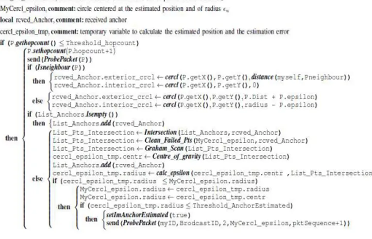
B. Pseudo-code
The pseudo-code for the Slsnj is shown in figure 3. Each anchor exact (equipped with GPS or Galileo) or estimated broadcasts its position through the control message P,and depending on number of hops traveled by the packet P we check its validity,if the number of hops is less than a certain threshold called ThresholdHopcount it is considered confirmed otherwise a packet is rejected.after we apply our method as described previously .
C. P roperties
Our localization technique meets three very important properties who have a significant impact on its performance:
• First, a node knows if its estimated position is close to its
real position. Let
be the distance between the center of gravity and the point, in the zone, furthest away from the center of gravity. Letd
err being the distance between the estimated position of a node and its real position, representing the position error. The node knows that derr
.Figure 3: Description of algorithm Slsnj
By using a predefined
threshold
, if
threshold
then the node has an estimation close to its real position. In this case the node becomes an estimated anchor and broadcasts its position and its
. When a node applies the approximation technique with an estimated anchor radius, it takes into account
.Consider a sensorX
calculating its position with an estimated anchorA
. If they are neighbors,X
trace two circles (belongs to
N
C ) centered in
A
of radius dAX and deduce that it is between these two circles. If they are not neighbors,X
deduces that it is not inside the circles centered atA
of radiusr
and belongs to a circle of radiusd
AX
,the definitions (4),(6),(9) and (11) become:si
a
i
N
(
u
)
:}
)
(
=
)
(
)
(
|
)
,
{(
=
2 2 2i u i ua a
i a i i
i i
ua
x
y
P
x
x
y
y
d
C
} ) (
) ( ) ( | ) , {(
= 2 2 2
1 i a i a uai ui
i i i i
u x y S x x y y d
Z
(18)
si
a
i
N
(
u
)
:} )
ˆ
( = ) ( ) ( | ) , {(
= 2 2
2i ua a
i a i i
i i
ua x y P x x y y d
C (19)
} )
ˆ
( ) ( ) ( ) ( | ) , {(
= 2 2 2 2
1
i ua a i a i i
i i i
u x y S r x x y y d
Z
(20)
• Second, a node can detect if some informations are
wrong. This case is illustrated in esxpresion i u
W .With its
bound error
, nodes reject the cloud points that are outside of circle centered at its estimated position and of radius
.for example, when a nodeu
detects a point of its cloud Su it outside in the circle centered atu
of radius
will not take it into account . This property is defined by the expressioni u
W .
• Third, convex hull algorithms as Graham scan [?] and
Jarvis march [?] allowed us to calculate the convex hull
) (S
conv a cloud of points with a very optimum complexity , of order O(nlog(n)) with
n
the number of points of the cloud, which allowed us to reduce consumption of CPU time (and therefore energy), but also allowed us to optimize particularly the consumption of memory storage ,focusing not on global interpretation of the network as in an algorithm of type Grid-scan, but only on points of the cloud. The improvement made allowed us to retain the properties functional Our localization technique despite the change in network size, and efficiently localize the nodes (continuously) and with a certain level of quality in different scales.D. Structure of the control message exchanged
nodes in its scope communication receive this message. The validation of a control message is limited by a threshold of validation ,called Threshold_hopcount.
Figure 4: Fields of the message ProbePacket
V. ADAPTATION OF DVM AND MADRD
DVM and MADRD determine periods when a node has to invoke its localization technique, related to mobility of nodes. It is necessary to adapt these two techniques in order to take into account accuracy of localization. SFR is not concerned by this problem because its period of time is constant. In these techniques, when a node is moving fast, localization will be carried out more often and conversely. But if a node is located with important error, it is necessary to invoke localization technique more often. Therefore, if node is located with high accuracy,methods DVM and MADRD do not need any change but if node obtains an approximate position then protocols DVM and MADRD have to take into account the error
.Lett
be the time returned by DVM or MADRD andt
' the time returned by our method when
is taken into account.If0
=
(ie. the position is exact)thent
=
t
' and if
r
(ie.the position is bad then
t
'=
0
.Between these two values ,
t
' varies linearlyr t t t'= .Thus,If
represents an important error,then periods during which a node should invokes its localization will be short and conversely if
is a small error. Perturbation of predictions in MADRD : In MADRD nodes calculate their positions related to predictions.A node computes its position related to its previous position. conversely if a small error. Perturbation of predictions in MADRD : In MADRD nodes calculate their positions related to predictions.A node computes its position related to its previous position.VI. SIMULATIONS
A. Environnement de simulation
Experiments were built upon the J-Sim simulator [9] dedicated to WSN simulations. It is a compositional, component based simulation environment. It is built upon the concept of autonomous component programming model. J-Sim is developed entirely in Java. The signal attenuation due to obstacles or other factors (e.g. use of unidirectional antennas) is simulated in J-Sim. Therefore, the vicinity of a node in terms of transmission range is not necessarily spherical. Note that there several simulators in the literature such as GlomoSim[41] , OMNET++[42] , OPNET[43] ,
NS-2[44] . The MAC layer is considered perfect and the transmission of messages are without loss in our simulation.
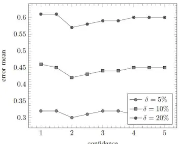
In order to allow easy comparison between different scenarios, range errors as well as errors on estimated positions are normalized to the radio range. For example, of position error means a distance of half the range of the radio between the real and estimated positions. The percentage of range errors is noted .
Figure 5: impact of threshold confidence
B. Results
Globally, the positions determined by a localization algorithm represent a geometrical layout of the physical positions of the sensors. This layout must be compared to the ground truth, or known layout of the sensors. It is important therefore that not only the error between the estimated and real position of each node is minimized, but also that the geometric layout determined by the algorithm matches well the original geometric layout. In order to have a unified approach for evaluate the accuracy of our technique and a solid frame for analysis of the scalability, we propose to use two metrics.
• MAE(Mean Absolute Error): The simplest way to describe localization performance is to determine the residual error between the estimated and actual node positions for every node in the network, sum them and average the result. Broxton et al in [45] do this using the mean absolute error metric (MAE), which, for each of n nodes in the network, calculates the residual between the estimated nodes and actual coordinates.
n
y
y
x
x
MAE
i i i
i n
i
2 2
1 =
)
ˆ
(
)
ˆ
(
=
(21)
with
(
x
i,
y
i)
the real position and(
x
ˆ
i,
y
ˆ
i)
the estimated postilions .[46] takes the RMS error over the network of n nodes and normalises it using the constant R. In Ahmed et als context, R represents average radio range, meaning the localization results are represented as a percentage of the average distance nodes can communicate over.
1)/2
(
)
ˆ
(
1
=
2
1 = 1 =
n
n
d
d
d
r
GDE
ijij ij n
i j n
i
(22)
with
d
ˆ
ij The estimated distance betweeni
andj
andij
d
The actual distance betweeni
andj
.This section analyses the performances of our three methods related to the techniques SFR, DVM and MADRD. Mobility model: The mobility model used in this paper is the random waypoint model [47]. It is the classical model used in the mobile network. In this model, velocities of nodes vary and a node can stop its move. Each node picks a random location and starts moving to it. As soon as the node reaches the destination, it picks another destination randomly and moves toward it. Our simulation uses the BonnMotion tool to generate the various scenarios of mobility where velocity and trajectory deviation of nodes vary. Each scenario runs during 90 seconds.
Simulation model: In our simulations, all messages are delivered. For easier comparison between different scenarios, range errors as well as estimations of position errors are normalized to the radio range. This technique is classical in the literature and allows comparisons with others methods. For example, of position error means a distance equal to half of the radio range between the real and estimated positions. In our scenarios, we use nodes in a square of . The transmission range of nodes is equal to . Among nodes, we randomly select anchors with representing a density of anchors in the square from to . Also, we consider measure errors of , and respectively. Analyse: In our method, it is possible that a node does not obtain an estimated position when it does not contain anchors in its neighborhood. This case depends on the anchors density. Therefore, if our simulations consider only the position average error rate of sensors, performances of our three techniques would not be shown due to this case. As a consequence, our results focus on the time during which a node is located with a position error lower than for MAE metric and for GDE metric. After this time, nodes are considered that they are badly positioned. For our analysis, we perform tests. For each scenario, we take into account the mean and we represent on graphs the confidence interval. Here, there is of chance that the real values belong to this interval.
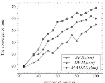
Figure 6: GDE Performances of SFR, DVM and MADRD with errors equal
to 5%
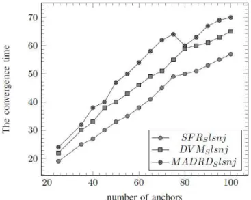
1) Without measure errors : In this section, we consider the ideal case where measure errors are equal to. The figures 7 and 9 show simulations with SFR, DVM and MADRD for GDE and MAE. These curves represent the time during which a node is located with a position error lower than for MAE for GDE. For example, in figures 5, when the network contains 70 anchors, a node is located with an error lower than during: 41.01s. Without surprise, accuracy of positions is based on the capability of nodes to calculate distances. MADRD provides better results than DVM and then SFR.
Figure 7: GDE Performances of SFR, DVM and MADRD without measure
2) Measure errors equal to
5%
: In this section, we introduce measure errors equal to 5%. Figure 6 and 8 shows that results obtained when nodes can calculate distances, is not influenced too much by measure errors in SFR, DVM and MADRD for MAE and GDE. To conclude, DVM provides better results than MADRD and then SFR.Figure 8: MAE Performances of SFR, DVM and MADRD with errors equal
to 5%
3) Conclusions of simulations : In These simulations show the performances of our method and show how to adapt SFR, DVM and MADRD, related to the network environment in order to provide good results. We note the impact of measure errors in MADRD since it is efficient only if it uses accurate positions. MADRD provides good results in a network environment without measure errors, but when we introduce errors, DVM is the best. Finally, phenomenons seen in an environment with measure errors equal to 5 errors equal to 10.
Figure 9: MAE Performances of SFR, DVM and MADRD without measure
errors
VII. CONCLUSIONS
This paper proposes the method for the localization problem when anchors and others sensors are mobile. this method take into account capabilities of nodes: nodes which can calculate either distances with their neighbors . Moreover, in order to answer to question when a node should invoke its position? related to network environment and capabilities of nodes, we adapted techniques SFR, DVM, MADRD, proposed in [14]. Our simulations show the performances of our method and determinate the technique the more adapted related to the network configurations.
REFERENCES
[1] Cerpa, J. Elson, M. Hamilton, J. Zhao, D. Estrin, and communications
technology,‖ in Workshop on Data communication in Latin America and the Caribbean, ser. SIGCOMM LA ’01. New York, NY, USA: ACM, 2001, pp. 20–41.
[2] A. Mainwaring, D. Culler, J. Polastre, R. Szewczyk, and J.
Anderson,―Wireless sensor networks for habitat monitoring,‖ in
Proceedings of the 1st ACM international workshop on Wireless sensor
networks and applications, ser. WSNA ’02. New York, NY, USA: ACM,
2002, pp. 88–97.
[3] T. van Dam and K. Langendoen, ―An adaptive energy-efficient mac
protocol for wireless sensor networks,‖ in Proceedings of the 1st international conference on Embedded networked sensor systems, ser.
SenSys ’03. New York, NY, USA: ACM, 2003, pp. 171–180. [Online]. Available : http ://doi.acm.org/10.1145/958491.958512
[4] Q. Fang, F. Zhao, and L. Guibas, ―Lightweight sensing and
communication protocols for target enumeration and aggregation,‖ in
Proceedings of the 4th ACM international symposium on Mobile ad hoc
networking & computing, ser. MobiHoc ’03. New York, NY, USA :
ACM, 2003, pp. 165–176.
[5] C. Intanagonwiwat, R. Govindan, D. Estrin, J. Heidemann, and F. Silva,
―Directed diffusion for wireless sensor networking,‖ IEEE/ACM Trans.
Netw., vol. 11, no. 1, pp. 2–16, Feb. 2003. [Online]. Available : http ://dx.doi.org/10.1109/TNET.2002.808417
[6] S. Madden, M. J. Franklin, J. M. Hellerstein, and W. Hong, ―Tag: a tiny aggregation service for ad-hoc sensor networks,‖ SIGOPS Oper. Syst. Rev., vol. 36, no. SI, pp. 131–146, Dec. 2002.
[7] A. Savvides, C.-C. Han, and M. B. Strivastava, ―Dynamic fine-grained localization in ad-hoc networks of sensors,‖ in Proceedings of the 7th annual international conference on Mobile computing and networking,
ser. MobiCom ’01. New York, NY, USA : ACM, 2001, pp. 166–179. [8] S. De, C. Qiao, and H. Wu, ―Meshed multipath routing with selective
forwarding: an efficient strategy in wireless sensor networks,‖ Computer
Networks, vol. 43, no. 4, pp. 481–497, 2003.
[9] J. Li, J. Jannotti, D. S. J. De Couto, D. R. Karger, and R. Morris, ―A
scalable location service for geographic ad hoc L. Girod, ―Habitat
monitoring: application driver for wireless For papers published in translation journals, please give the English citation first, followed by the original foreign-language citation routing,‖ in Proceedings of the 6th annual international conference on Mobile computing and networking,
ser. MobiCom ’00. New York, NY, USA: ACM, 2000, pp. 120–130. [10] J. Heidemann and N. Bulusu, ―Using geospatial information in sensor
networks,‖ 2001.
[11] C. Schurgers, G. Kulkarni, and M. B. Srivastava, ―Distributed ondemand
address assignment in wireless sensor networks,‖ IEEE Trans. Parallel
Distrib. Syst., vol. 13, no. 10, pp. 1056–1065, Oct. 2002.
[12] N. B. Priyantha, H. Balakrishnan, E. Demaine, and S. Teller, ―Mobile-
Assisted Localization in Wireless Sensor Networks,‖ in IEEE
INFOCOM, Miami, FL, March 2005.
[14] S. Tilak, V. Kolar, N. B. Abu-Ghazaleh, and K.-D. Kang, ―Dynamic
localization protocols for mobile sensor networks,‖ CoRR, vol.
cs.NI/0408042, 2004.
[15] B. Hofmann-Wellenhof, H. Lichtenegger, and J. Collins, Global Positioning System: Theory and Practice, 5th ed. Springer, Feb. 2001. [16] P. Bahl and V. N. Padmanabhan, ―RADAR: an in-building RF-based user
location and tracking system,‖ INFOCOM 2000. Nineteenth Annual Joint
Conference of the IEEE Computer and Communications Societies. Proceedings. IEEE, vol. 2, pp. 775–784 vol.2, 2000.
[17] N. Bulusu, J. Heidemann, and D. Estrin, ―Gps-less low cost outdoor
localization for very small devices,‖ IEEE Personal Communications
Magazine, vol. 7, no. 5, pp. 28–34, October 2000.
[18] ―Adaptive beacon placement,‖ in Proceedings of the The 21st International Conference on Distributed Computing Systems, ser. ICDCS
’01. Washington, DC, USA: IEEE Computer Society, 2001, pp. 489–. [19] S. Capkun and J.-P. Hubaux, ―Secure positioning of wireless devices with
application to sensor networks,‖ in INFOCOM, 2005, pp. 1917– 1928. [20] X. Cheng, A. Thaeler, G. Xue, and D. Chen, ―Tps: A time-based
positioning scheme for outdoor wireless sensor networks,‖ in IEEE
INFOCOM, 2004, pp. 2685–2696.
[21] L. Fang and W. Du, ―A beacon-less location discovery scheme for
wireless sensor networks,‖ in In Proceedings of IEEE INFOCOM, 2005, pp. 13–17.
[22] L. Girod and D. Estrin, ―Robust range estimation using acoustic and
multimodal sensing,‖ vol. 3, 2001.
[23] T. He, C. Huang, B. M. Blum, J. A. Stankovic, and T. Abdelzaher,
―Range-free localization schemes for large scale sensor networks,‖ in Proceedings of the 9th annual international conference on Mobile
computing and networking, ser. MobiCom ’03. New York, NY, USA :
ACM, 2003, pp. 81–95.
[24] Jeffrey, ―SpotON : An Indoor 3D Location Sensing Technology Based on RF Signal Strength
[25] L. Hu and D. Evans, ―Localization for mobile sensor networks,‖ in Proceedings of the 10th annual international conference on Mobile
computing and networking, ser. MobiCom ’04. New York, NY, USA :
ACM, 2004, pp. 45–57.
[26] K. Langendoen and N. Reijers, ―Distributed localization in wireless
sensor networks : a quantitative comparison,‖ Comput. Netw., vol. 43, no.
4, pp. 499–518, Nov. 2003.
[27] L. Lazos and R. Poovendran, ―Serloc : Robust localization for wireless
sensor networks,‖ ACM Trans. Sen. Netw., vol. 1, no. 1, pp. 73–100, Aug. 2005.
[28] Isaac Amundson and Xenofon D. Koutsoukos. 2009. A survey on localization for mobile wireless sensor networks. In Proceedings of the 2nd international conference on Mobile entity localization and tracking in GPS-less environments (MELT'09), Richard Fuller and Xenofon D. Koutsoukos (Eds.). Springer-Verlag, Berlin, Heidelberg, 235-254. [29] A. Nasipuri and K. Li, ―A directionality based location discovery
scheme for wireless sensor networks,‖ in Proceedings of the 1st ACM international workshop on Wireless sensor networks and applications,
ser. WSNA ’02. New York, NY, USA: ACM, 2002, pp. 105–111. [30] D. Niculescu and B. Nath, ―Ad hoc positioning system (aps,‖ in In
GLOBECOM, 2001, pp. 2926–2931.
[31] ——,―DV Based Positioning in Ad Hoc Networks,‖ Telecommunication Systems, vol. 22, no. 1, pp. 267–280, Jan. 2003.
[32] A. Rao, S. Ratnasamy, C. Papadimitriou, S. Shenker, and I. Stoica,
―Geographic routing without location information,‖ in Proceedings of
the 9th annual international conference on Mobile computing and
networking, ser. MobiCom ’03. New York, NY, USA: ACM, 2003,
pp. 96–108.
[33] N. Sastry, U. Shankar, and D. Wagner, ―Secure verification of location
claims,‖ in Proceedings of the 2nd ACM workshop on Wireless security, ser. WiSe ’03. New York, NY, USA: ACM, 2003, pp. 1–10.
[34] C. Savarese, J. M. Rabaey, and K. Langendoen, ―Robust positioning algorithms for distributed ad-hoc wireless sensor networks,‖ in Proceedings of the General Track of the annual conference on
USENIX Annual Technical Conference, ser. ATEC ’02. Berkeley, CA,
USA: USENIX Association, 2002, pp. 317–327.
[35] A. Savvides, H. Park, and M. B. Srivastava, ―The n-hop multilateration
primitive for node localization problems,‖ Mob. Netw. Appl., vol. 8,
no. 4, pp. 443–451, Aug. 2003.
[36] Y. Shang, W. Ruml, Y. Zhang, and M. P. J. Fromherz, ―Localization
from mere connectivity,‖ in Proceedings of the 4th ACM international symposium on Mobile ad hoc networking & computing, ser. MobiHoc
’03. New York, NY, USA; ACM, 2003, pp. 201–212.
[37] L. Doherty, K. S. J. Pister, and L. El Ghaoui, ―Convex position
estimation in wireless sensor networks,‖ in INFOCOM 2001. Twentieth Annual Joint Conference of the IEEE Computer and Communications Societies. Proceedings. IEEE, vol. 3, 2001, pp. 1655–1663.
[38] Xuemin Shen, Jon W. Mark, and Jun Ye. 2002. Mobile Location Estimation in CDMA Cellular Networks by Using Fuzzy Logic. Wirel. Pers. Commun. 22, 1 (July 2002), 57-70. DOI=10.1023/A: 1016025802932 http://dx.doi.org/10.1023/A:1016025802932.
[39] R. Graham, ―An efficient algorithm for determining the convex hull of a finite planar set,‖ Information Processing Letters, pp. 132–133.
[40] R. A. Jarvis, ―On the identification of the convex hull of a finite set of
points in the plane,‖ Inf. Process. Lett., vol. 2, no. 1, pp. 18–21, 1973. [41] ―About glomosim,‖ http://pcl.cs.ucla.edu/projects/glomosim/, cited July
2011.
[42] ―Omnet++ community site,‖ http://www.omnetpp.org/, cited July 2011. [43] ―Opnet technologies,‖ http://www.opnet.com/, cited July 2010. [44] ―The network simulator,‖ http://www.isi.edu/nsnam/ns/, cited July
2010.
[45] M. Broxton, J. Lifton, and J. A. Paradiso, ―Localization on the pushpin computing sensor network using spectral graph drawing and
mesh relaxation,‖ SIGMOBILE Mob. Comput. Commun. Rev., vol.
10, pp. 1–12, January 2006.
[46] A. A. Ahmed, H. Shi, and Y. Shang, ―Sharp : A new approach to relative localization in wireless sensor networks,‖ in Proceedings of the Second International Workshop on Wireless Ad Hoc Networking -
Volume 09, ser. ICDCSW ’05. Washington, DC, USA: IEEE
Computer Society, 2005, pp. 892–898.
[47] T. Camp, J. Boleng, and V. Davies, ―A survey of mobility models for ad