Design and Development of Stewart Platform
using Air Muscles
M.Sivaramakrishnaiah
Asst.professor of Department of Mechanical Engineering
Sri Venkateswara college of Engineering and Technology,(AUTONOMOUS)Chittoor, Andhrapradesh, India
S.Ramesh Babu
Asst.professor of Department of Mechanical Engineering
Sri Venkateswara college of Engineering and Technology, Chittoor,(AUTONOMOUS) Andhrapradesh, India.
Dr. P.Nanda Kumar
Prof.of. Mech. Egg.NBKR Institute of Science & Technology, Vidyanagar, S.P.S.R Nellore (Dt.) AP, India.
Abstract- This report mainly deals with the replacement of hydraulic or pneumatic cylinders in Stewart platform by newly developed actuators known as “Air muscles” which functions like pneumatic or hydraulic actuators. A preliminary attempt has been made to design and develop the Stewart platform with the use of Air muscles.In this development, the Stewart platform has four air muscles (6mm diameter) connected between the two platforms with the help of aluminium hooks. one of the platforms is fixed and another is free to take positions. a compressor is used to supply the air under pressure into a two-way common manifold which consists of six flow control valves for actuating air muscles.Due to the flexibility of air muscles, they cannot carry the compressive loads. so as to obtain the exact positions, this platform is inverted. the larger size platform is fixed to a stand and the air muscles along with smaller size platform are hanged in air. the smaller size platform is loaded with weights so that the air muscles will be under tension. now these air muscles tend to expand contract between both the platforms while operating with pressures from 1 to 5 bar in order to obtain the different positions. during the operation period one LASER light is fitted to the smaller platform to recognize the various positions.
Keywords – Air muscles, platform, compressor, operating pressure.
I.INTRODUCTION
1. Stewart platform:
A Stewart platform is a closed loop manipulator whose six-DOF End-effecter is connected to a base platform by six actuation using prismatic joints[1].The basic Stewart platform is made up of six extensible struts, opposing to the previous design, with only one DOF (the cross section is non –circular, does not allow rotation. The six struts are fixed to the base and the platform using ball-socket joints. This design is dated up to three decades ago; the first design was introduced in 1965 by D. Stewart for use in air craft simulator. This elementary design had some limitations in its range of motion because of such a design. The initial design of the platform, since the time it was first adopted, requires many changes. Because, the current time is the time of computer controlled devices. In addition, with the advance in the field of robotics, the necessity of inventing positional devices with very high accuracy (may reach sub-micron) has become necessary.
Fig 1.STEWART PLATFORMS TYPES
1.1AIR MUSCLE
Air Muscle is an actuator that works very similarly to a human muscle—it contracts by thickening. Inside the black pouch is a balloon. High pressure air pumped through the tube inflates the balloon causing the muscle to shorten by as much as 40%. The force it provides decreases as it contracts, and the first few percent of the contraction is very powerful indeed. Air Muscles can provide substantial pulling force for their small size; they can exert force 400 times their weight. Typical DC motors or pneumatic actuators can exert about 16 times their weight. The largest of the standard Air Muscles is 11 inches long, weights less than 3 ounces, and can lift 154 pounds!
An Air Muscle has a power-to-weight ratio as high as 400:1, vastly outperforming both pneumatic cylinders and DC motors that can attain a ratio of only about 16:1. It has been in continuous development for advanced robotics work by Shadow since 1982, and is now available for use in a variety of applications as a powerful, lightweight actuator. Air Muscles are normally operated using compressed air in the 0-60psi (0-4 bar) rang.
Fig 2:Standared Air muscle
1.2 DEGREES OF FREEDOM CALCULATION:
Considering the base to be fixed, the degrees of freedom analysis goes as follows: Number of moving parts: 13 parts (a platform, six extensible struts and six base struts). Total DOF of the system: 13x6=78 DOF
DOF Analysis: Number
Interface
Constraints
DOF
DOF Type
6 Base/Struts: ball and
socket joint 3 3 RRR
6
Base struts/extensible strut
lower end
5 1 T
6
Strut upper end/Platform: ball
and socket joint
3 3 RRR
Table 1.:DOF of Stewart plat from
System DOF = 78-66= 12 DOF
Since the required DOF of the system is only 6 DOF (TTT, RRR), therefore this implies the existence of local motilities. By examining the system, the existence of six local motilities is conformed between the ball and socket joints on the platform. Therefore:
Calculated DOF= Required/Basic DOF + Local motilities’ 12=6+6
Air Muscles work when twisted, bent around corners, or under water. It even has a similar power profile to a human muscle: the force exerted decreases as it contracts, just like the strength of your biceps is maximum when your arm is extended and decreases as your arm is bent.
1.3 WORKING
The inner rubber tube is inflated by entering air at a pressure, usually limited to 3.5 bar. The movement of this tube is constrained by the braid. When the tube gets inflated it experiences a longitudinal contraction. This would create a pull at both ends of the tube. Usually one end of the tube will be attached to somewhere so that force can be applied from one end. This pull when effectively utilized could provide the necessary motion. The working of the Air Muscle closely resembles that of the natural muscle and hence the name Muscle given to it along with Air. The figure below shows the physical appearance of the muscle at different stages of its working.
1.4 PROPERTIES
The Air Muscle behaves in a different manner to the pneumatic cylinder or other actuator. As the Air Muscle contracts under constant pressure, pulling force produced between the end points decreases. The maximum force at a given pressure is obtained when the Air Muscle is pulled out as far as possible. If the Air Muscle is not taught, then it will not yield its full force.
At a constant pressure, the curve at the Force against Length is as shown fig 3. below.
Note that, if the Air Muscle is not fully stretched at the start of the movement, initial force will be lost and the Air Muscle will underperform by a significant margin.
The relationship between pressure and force is linear at constant extensions. This allows the movement distance to be set by regulating the pressure in the system.
Characteristics of pressure, length and force are given below. These measurements are typical of Air Muscles of the specified size.
1.5 PERCENTAGE CONTRACTION
PRESSURE LOAD
0.5
KG
1
KG
2
KG
3.2
KG
0
Bar
N/A
3%
2%
2%
1%
2
Bar
12% 10%
7%
5%
3%
4
Bar
20% 20% 17% 11%
Table2 .Percentage Contraction of Active Fig 3. curve at the(constant pressure,)
Length for 6mm Air Muscle Force against Length
1.6. SOURCES OF COMPRESSED AIR
by a standard workshop compressor. Note that the usual output of such a compressor is around 8 bar, and therefore the supply will need to be regulated near the muscles.Air can be supplied occasionally or for test purposes by bicycle pumps or car foot pumps (since the volume of air used can be relatively low, it is feasible to use a manual pump, with a reservoir of air, to supply air).Air can be supplied portably and simply by canisters of liquefied gas, such as photographic gas canisters. However, these are relatively expensive, and if used to supply a large amount of air, tend to freeze.Whilst air could be supplied from a high-pressure cylinder, we do not recommend this. Compressed air above 10 bar is something to leave to the experts.
II.DESCRIPTIONOFCOMPONENTS 2.1AIR MUSCLES
[2]The core of air muscle is rubber tube wrapped in a tough plastic weave. Here we are using six number of air muscles (6 mm diameter) to connect with the help of aluminium hooks.
Application: [3] The SHADOW hand, developed by Shadow Inc., uses 20 air muscles to fluidly actuate a 21 DOF, five-fingered humanoid hand with a 2 DOF wrist.
Fig 4. Airmuscle of 6mm
2.2 PLATFORM
The two platforms are used in , One platform is larger in size which is fixed to a stand and other one is smaller in size. The platform is provided with holes at outer surface to connect with muscles.
LARGER PLATFORMS:
MATERIAL : Acrylic SHAPE : Circular
SIZE : 150mm diameter
SMALLER PLATFORMS:
MATERIAL : Acrylic SHAPE : Circular
SIZE : 80mm diameter
2.3 COMMON MANIFOLD
One Aluminium common manifold is used to connect six valves in which four valves for four air muscles, one for air inlet and one for air for air exhaust. This is readily available in market.
2.4 CONTROL VALVES
Six numbers of manually operated two-way valves are used in which four valves are used for four air muscles, one for air inlet and another one is used for air exhaust. These are readily available in market.
The valves used for this purpose are ball valves as shown below 2.5 PUSH-IN-FITTINGS
Four numbers of push-in-fittings are used to connect the tubes of four air muscles to the valves. 2.6 HOSES
All the air in the system is at 5 bar or less, and therefore standard polyurethane hoses (air line piping) are used. Although they are more flexible and are not rated for use at temperatures above25°C.
OUTSIDE DIAMETER : 4mm INSIDE DIAMETER : 2.5mm
Air is supplied reliably and continuously by a standard workshop compressor. Note that the usual output of such a compressor is around 8 bar, and therefore the supply will need to be regulated near the muscles.
III.CONTROLSYSTEM
Air muscle
Gauge
IV. COMPONENTS USED IN THE ACTUAL CONTROL SYSTEM:
In actual control system, certain components are used to enable the optimization of the motion. Therefore selection of the right components is a critical factor to ensure the control work as what is required.
The components used are 1. Pressure unit 2. Flow control valve 3. Two way control valve 4. Push-in fitting
5. 4mm tubing 6. Regulator
4.1 FUNCTIONS OF THE COMPONENTS USED: PRESSURE UNIT:
Pressure unit is a standard workshop compressor which is used to supply the compressed air to the control system.
FLOW CONTROL REGULATOR:
Flow control regulator controls the speed of a pneumatic cylinder. An adjustable restrictor controls the exhaust air flow. The inlet flow is unrestricted full bore.
TWO WAY CONTROL VALVES:
They are used to help in control of air muscles motion.
PUSH-IN FITTINGS (for 4mm tubing):
Push in fitting is used to connect the tubing from one component to another to supply compressed air to the parts. The fitting can withstand 10 bar of compressed air. It acts as a connector.
Fig 6 Block diagram of Pneumatic circuit
HOSES:
These are made of polyurethane or nylon, used to channel compressed air to all parts.
PRESSURE REGULATOR:
A pressure regulator is used to control and determine the pressure from the supply or pressure unit. It will enable one to prevent any parts from being spoilt due to over pressure.
V. DESIGN AND FABRICATION FABRICATION AND ASSEMBLY OF THE STRUCTURE:
1. Top and bottom platforms 2. Aluminium hooks 3. Common manifolds 4. Control valves 5. Push-in fittings 6. Air compressor
Top and bottom platforms are machined in college workshop. Aluminium hooks, common manifold, control valves, push-in fittings are readily available in market. Air muscles along with 4mm tubing are imported from Shadow Robot Company in KOREA. All these components are assembled in the workshop.
VI. PRINCIPLE OF OPERATION:
The main principle of operation is when the compressed air is compressed into the air muscles the rubber tubes which are inside the air muscles expand. Due to this, the air muscle shortens in lengths. So the movable (small) platform takes different positions.
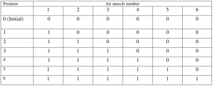
VII. TESTING AND EXPERIMENTAL RESULTS:
The smaller size platform is loaded with 1 kg weight so that the air muscle will be under tension. Due to the lack of space availability on the small size platform the platform is tested with 1 kg weight. The platform can give 64 positions when operated its minimum and maximum lengths only. At different pressure combinations the platform can give more than 64 positions. But due to the increase of project cost, here used manually operated two way valves instead of solenoid valves. So that only six positions are shown including initial position. They are
Position Air muscle number
1
2
3
4
5
6
0 (Initial)
0
0
0
0
0
0
1
1
0
0
0
0
0
2
1
1
0
0
0
0
3
1
1
1
0
0
0
4
1
1
1
1
0
0
5
1
1
1
1
1
0
6
1
1
1
1
1
1
During the operation period one laser light is fitted to smaller platform to recognize the various positions.
The experimental setup is tested in college workshop. The positions of movable platform are plotted on graph sheets to recognize the variations with the help of laser light. The initial and return positions are not exactly identical but we got almost same positions with small variations.
The reasons found for those variations are as follows:
The air muscles are not rigid like pneumatic or hydraulic cylinders
All the muscles are not having same length because of elastic material used to make the air muscles. Lack of high accuracy pressure gauges.
End joints of air muscles are not rigid.
So we are able to show only 7 positions which are shown in the graphs.
VIII. ADVANTAGES AND DISADVANTAGES: ADVANTAGES:
The experimental setup has the following advantages
1. The experimental setup requires only less number of components for fabrication and it does not have complicated parts.
2. Easy to fabricate and design.
3. The air muscles are lighter in weight compared to hydraulic or pneumatic cylinders. Due to that the setup can be carried to anywhere easily.
4. Air muscles are cheaper to buy and easy to install than other actuators and pneumatic cylinders so that setup cost is less.
5. Air muscles can be operated when twisted axially bent round a corner and need no precise aligning. So the consumption is less for assembling.
DISADVANTAGES:
The setup has following disadvantages
1. Air muscle is a soft actuator, their systems are inherently complicit.
2. The setup cannot carry the compressive loads due to flexibility of air muscles. 3. It should be handled carefully due to soft material.
4. Life of air muscle is less as compared to hydraulic or pneumatic cylinders. APPLICATIONS:
The present design of articulating of structure is expected to be useful in wide applications in many areas more areas than one, After successful development with additional accessories such as cameras as vision sensors, antenna for receiving and transmitting signals, mobile base for motion and computer controls with data acquisition systems, it can be, In chemical industries for pipe line inspection. For flight simulation.
Useful like surgical robots in medical field. Useful to the entertainment industry for virtual reality motion rides. Useful to replace the conventional single cable hoisting technology currently being used on helicopters for use as an air crane. Useful for positioning satellite dishes. Useful to replace conventional crane hoist mechanism in cranes for easy control by the crane operator.
IX. CONCLUSION AND RECOMMENDATION:
From the discussion, the parallel manipulator which has been developed is a starting of some future development of such parallel manipulator. However further study on this particular manipulator is essential as to increase the efficiency, usability, durability and applicability. Therefore there are many areas in the parallel manipulator, which can be tested and further study. Examples of these areas are the control of the system so that more points are position can be reached by the manipulator, the precision and accuracy, analysis of the design using finite element analysis and most important the applicability of the design in all the possible application. In the process of design, developing, studying and testing the model, time is the biggest limitation therefore further study should be continued on this model in order to achieve the best results.Another important subject should be applied to the parallel manipulator as a flight simulator but certain modification can be made enable the possibility of the application.
X. PHOTOGRAPHS:
Fig Assembly of stewartplatform using Fig: platforms with Airmuscle connecting value Airmuscle with Compressor
REFERENCES
[1] A Stewart platform based system for Ankle Telerehabilitation Autonomous Robots 10,203-212,2001 c 2001 klower Academic publishers manufactured in the Netherlands.
[2] http://www.imagesco.com/articles/airmuscle/AirMuscleDescription01.html [3] http://www.shadowrobotcompany.com/
[4] http://www.mel.nist.gov/namt/projects/hexapod [5] http://www.ingersoll.com/