Analysis and Design of Marine Berthing Structure
T.Vivek
1,
R.Durga prasad
2 1P.G. Student, Department of Civil Engineering, Swamy Vivekananda Engineering college, Kalavarai, bobbili, vizianagaram, Andhra Pradesh, India.
2
Assistant Professor, Department of Civil Engineering, Swamy Vivekananda Engineering college, Kalavarai, bobbili, vizianagaram, Andhra Pradesh, India.
ABSTRACT
In the present dissertation a berthing structure was analyzed and designed using different load conditions and the best possible way to construct a new berthing structure was described. All the suitable and useful data was adopted from the proposed site location at Visakhapatnam Port and studied carefully before designing the structure. The proposed berthing structure was modeled with suitable geometry using STAADPRO, after which all considerable loads on the structure were induced and analyzed carefully. Different sectional dimensions were trialed during the analysis and the most acceptable structure was designed with providing all structural members with suitable reinforcement and satisfying all marine safety conditions.
I.
INTRODUCTION
The berthing structures are constructed for the berthing and mooring of vessels to enable loading and unloading of cargo and for embarking and disembarking of passengers, conveyances etc. The orchestrating and design of berthing structures depend on sundry factors. In the present study of the project, we described a felicitous way to design an incipient berthing structure with example of one of the proposed berthing structure in Visakhapatnam port. So afore analyzing and designing, the influence factors which effected on the structure were taken into consideration such as soil characteristics of the proposed location, environmental conditions and range of traffic.
All the rudimental Data was adopted from Visakhapatnam port which were supposed to be utilized in the project such as geotechnical data, environmental data, and traffic forecasting data. The entire Berth length of 100m was divided into 3 units of each 33.33 in length with an expansion joint of 40mm between successive units and proposed in the inner harbour, designated for handling liquid cargo like Sulphuric acid, Phosphoric acid, phosphoric acid, edible oils etc. The details of the structural element are discussed under the conceptual design. The design dredge level is taken as -16.10m.
A berthing structure is a capital injuctively authorizing project, thereby; optimum utilization of both space and capital becomes essential. This denotes that felicitous orchestrating of the sundry units undergo from congestion or inflexibility due to short comings in orchestrating or due to erroneous estimate of the traffic and or land requisite. Berthing structures vary generally from port to port. The number of berths will depend upon the number of ships to utilize the port and the time it will take to ejection and take on cargo or passengers. Berthing structures should be located in the most bulwarked part of the harbor or along the the wind and waves as possible.
II.
DESIGN PARAMETERS OF BERTHING STRUCTURES
2.1.1 PLACE OF CONSTRUCTION
The determination of location influenced by easy accessibility for ships, sufficient draft availability during the year, favorable metrological and wave hydro dynamic conditions. Amount of the forces on marine structure depends on last two factors.
2.1.2 TYPES
After determination of the location for structure, have to select the kind of structure for construction and the factors controlling the selection of the kind of structure are depending on the conditions of water flowing and Geotechnical properties of soil.
Classifications of berthing structure are basically Piers and Wharfs
1)Wharf – A berthing structure which is parallel to shore line. It is generally adjacent to the shore, and may not be very near to shore
2) Pier - A berthing structure which is project into water that means perpendicular to shore. This structure need not be exactly perpendicular to shore; it may be with some angle to shore. These structures also are like T or L shape.
2.1.3WAYOFSELECTIONTOCONSTRUCT BERTHING STRUCTURES Type of berthing structure and utilized material for construction depend on various factors
Local customs and practice: for suppose, Europe used the massive quays, whereas, America used the open and light structures.
Material availability
Construction cost.
Method of construction.
Dimension and mass of ships handled in the port.
2.1.4 REQUIRED NUMBER OF BERTHS
The determination of number of berths depends on handling of traffic in port .the planning of a new terminal was influenced by initial investment.
The approximate relations used for the determination of the required number of berths are: N1= W/ R* H * D
Where,
N1= essential amount of berths for a certain cargo.
W = yearly amount of this cargo imported and exported(T/year).
R = handling rate of this cargo on the berth. (T/ hour) H = number of working hours per day. (Hour/ day) D = amount of working days per year. (Day/ year)
N1 is calculated for each kind of cargo, and the overall number of berths in the port N for all types of cargo is: N = N1 + N2 + N3 +……..
2.1.5 LONGITUDINAL DIMENSION OF BERTH
The function of the terminal and size of vessel determines the berth length and ships calling to port also influence the length
Berth length required for main line vessels is 275+25=300m Berth length required for feeder vessels is 150 +50 = 200m
2.1.6 REQUIRED AREA OF BERTH
Berthing territory ought to be focused around the length and broadness of the biggest size of boat utilizing for the berths. Berthing range is the zone before the berthing structure needed for berthing vessels furthermore suits the administration vessels. Length needed for berthing a vessel and its surging developments because of wave and momentums are for the most part defined as 10% of boats length, subject to at least 15m. d1 ought not be short of what (L1+l2)/20 and d2 >= (L2+l3)/20 where there are solid obstructions, the safe separation of d0 = 25 – 30 m is permitted. The width of the berthing zone ought to be 1.15 B + b where B is the shaft width of the outline vessel and b is the width of the attending craft.
2.1.7 DRAFT MAINTENANCE ALONG THE BERTH
Fig: 2.1.7 draft representation along the berth 2.1.8 WIDTH OF BERTH APRON
Cover width of a quay is reliant on the sort of equipment utilized for stacking and exhausting operations. The apron width is picked focused around the facilities gave. The width of the berth will in a general sense rely on upon space prerequisites of substantial obligation boat to shore cranes which must have versatility all through the length of berth. The necessity, for the width of apron varies with the separation from berthing line to the first rail track of the gantry crane and with the back compass of the crane. Measurements of the holder cranes may shift appropriately to the outline and limit of the crane. Obliged width of the cover for commonplace compartment crane is 2 to 4 m for the separation from water front to the first rail, 20 to 35 m for the track width of the crane and 8 to 16 m for back achieve, making a sum of 30 to 55 m towards back.
2.1.9 ELEVATION OF DECK
Deck elevation is fine-tuned at or above the highest high spring dihydrogen monoxide level plus half the wave height near the berth plus a free board of 1m. The maximum distance of quay edge inclusive of fine-tuned fenders from the outer track of the crane is about 2.65m.
2.1.10 TURNING CIRCLE
Measurements of turning loop are subject to the predominating power of wind, current and the force of tugs accessible for aid. The accompanying criteria may be followed in either case for figuring the radius of the circle: i)Without tug support - 1.7 l
ii)With tug support - 0.85 L
The third era boats will have a draft of 12.2 m. Consequently a navigational channel which can suit these boats is important with a base depth of 13.5 m.
2.1.11 AREA REQUIRED FOR STACKING PURPOSE
The zone needed for capacity of holder inside the terminal relies on upon the accompanying elements 1) Throughput anticipated that will pass through the terminal for every annum.
2) Dwell time of containers inside the terminal. This is the mundane time a container would utilize in the yard after import and afore re-trade in a transit terminal.
3) The kind of container handling equipment utilized for stacking.
4) Average stacking height: Containers are not stacked to the most extreme tallness in all the spaces inside the stacking region. This is obliged to empower the taking care of supplies to get the lower holders in the stack for release. Moreover, containers need to be isolated by end, weight class, and direction of peregrinate in some cases by sorts and frequently shipping line or accommodation. Subsequently there is dependably a proportion between the mundane stacking stature and most extreme stacking tallness
5) Peaking factor: This is the degree of the crest activity to the average traffic, generally taken in the middle of 1.3 to 1.4.
III.
INDUCED LOADS ON BERTHING STRUCTURE
The whole EQ (Eastern Quay)-10 berth length of 100.07 m is separated into 3 units of every 33.33 long with an expansion joint of 40mm between progressive units
The proposed EQ-10 berth is implied for taking care of fluid freight like Sulphuric corrosive, Phosphoric corrosive, phosphoric corrosive, eatable oils and so on the subtle elements of the structural component are talked about under the applied configuration .in spite of the fact that the concession understanding accommodates dredging must be conveyed up to -16.10m .henceforth the outline dredging level is taken as -16.10m
IV.
ANALYSIS OF INDUCED LOADS
4.1.1 DEAD LOAD
Fig: 4.1.1 Dead load representation on structure
All dead loads of and on structures identifying with docks and harbor ought to be evaluated and included in the design configuration. Dead loads comprise of the weight of all parts of the structure and also the weight of all permanent connections. The DL of a port related marine structure constitutes a relative little rate of the total burden acting up on the structure.
Wearing coat (Apron) = 0.20 X 25 = 5 kN/m2(density of the concrete is taken 25 kN/m3)
Slab weight = 0.30 X 25 = 7.55 kN/m2
Beams
Transverse beams = 1.10 X 1.80 X25 = 50kN/m
Longitudinal beam = 1.10 X 0.60 X 25 =16.5 kN/m
Pile =1.70X21.65X25=920.12 kN/m 4.1.2 LIVE LOAD
material, for example, general load, mass freight, holders and burdens from vehicular movement of assorted types, including trucks, trailers, track, and cranes, containers handling equipment and development plant constitute vertical1ive loads. Vertical LL comprise of the weight of all versatile equipment’s on the structure
Serial Functioning Truck Uniform
number berth loading vertical
LL(T/m2)
1 Passenger berth B 1.0
2 Bulk unloading A 1.0 to 1.5
and unloading berths
3 Container berths A or AA 3 to 5
or 70R
4 Cargo berth A or AA 2.5 to 3.5
or 70R
5 Heavy cargo A or AA 5 or 6
berth or 70R
6 Small boat berth B 0.5
7 Fishing berth B 1.0
The function of berth related to Truck loading A or AA or 70R (Heavy cargo berth) so we are adopted 50 kN/m2.
4.1.3 BERTHING LOAD
Fig: 4.1.3 berthing load representation on structure
Berthing Energy - When an approaching vessel strikes a berth a level power follows up on the compartment. The magnitude of this power Depends on the kinetic energy that can be ingested by the Fendering framework. The response energy for which the berth is to be composed can be acquired and Deflection-response outlines of the fendering framework picked. These outlines are realistic from bumper producers the Kinetic energy E, bestowed to a fendering framework, by a vessel moving with speed V m/s is given by:
W V 2
E 2
D
g (Cm )(Ce )(Cs )
WD = displacement tonnage (DT) of the vessel
V = velocity of vessel in m/s, normal to the berth g = acceleration due to gravity in m/s2
Cm= mass coefficient
Ce= eccentricity coefficient
Cs= soft coefficient
E 200000X 0.102X 0.51X1.60X 0.95 =80kN.m
2 X 9.81
4.1.4 MOORING LOAD
Fig: 4.1.4 mooring load representation on structure
The mooring burdens are the lateral loads brought about by the mooring lines when they pull the boat into or along the dock or hold it against the powers of wind or current. The most extreme mooring burdens are because of the wind compels on uncovered range on the open side of the boat in light condition
F Cw Aw P
F = force due to wind in Kg Cw= shape factor = 1.3 to 1.6
Aw= wind age area in m2
P = wind age pressure in m2to be taken in accordancewith IS: 875-1964 The wind age area (Aw) can be predictable as follows: Aw= 1.175Lp (DM-DL)
Where
Lp= length between perpendicular in meter DM= mould depth in m, and
DL=average light draft in m.
Actual this is the definite procedure but port engineers suggested that bollard pull =900kN is adopted (Design load) Generally mooring load act in various angle of forces so we have to resolve on the mooring point while designing the berth. And spacing taken as bollard to bollard is 15m c/c ,if suppose we fixed 7 bollards then the load on each bollard is 900/7 =F =128kN
Resolving of forces on mooring points are Horizontal component = Fcos = 90kN Vertical component = FSin = 90kN
Generally angle is taken as 450 here if necessary need to calculate at different angles as per maximum ship moment observations.
4.1.5 CURRENT LOAD
Loads because of Current - Pressure because of flow will be connected to the zone of the vessel beneath the water line when completely stacked. It is roughly equivalent to w v2/2 g per square meter of range, where v is the velocity in m/s and ID is the unit weight of water in tones/ml. The boat is for the most part berthed parallel to the current with powerful currents and where berth arrangement really goes astray from the bearing of the current, the' likely force should be considered by any familiar method and taken into account.
F= w v2/2 g
=1.025 tonnes/m3 Unit weight of water ( w)
Velocity of current ( v) =0.26m/s
Acceleration due to gravity = 9.81m/s2
F = 0.035kN/m2
For 1 unit of berth F = 0.035X33X21.65 =25kN 25kN for 12 piles for each pile F = 2.02 kN
Load distribution is converted as uniform on pile F= 2.02/21.65 =0.096KN/m
4.1.6 WIND LOAD
Wind contributes primarily to the lateral loading on a pier. It blows from many directions and can vary without detect. The wind impinging upon a surface increases the pressure on that surface and results in a force loading. However, given the construction characteristics of an open pier, the loading on the structure itself is minor compared with the wind effects of the ship moored along side. The exposed, directional, surface region of the ship is susceptible to wind loading which is then transferred to the pier. When designing a pier, historical wind data, along with the design ship size, is analyzed to size the structural members according to the predominant wind direction.
Design wind speed (Vz) = Vbk1k2k3
Vb= basic wind speed
k 1= probability factor (Risk coefficient)K2= terrain, height and structure size factor K3= topography factor
Vz = (50)(0.92)(1.05)(1) =48.3m/sec
Design wind pressure = 0.6(vz)2 p=1400N/m2
=1.4kN/ m2
Now the design wind pressure is resolved as nodal loads on structure
=1.4X 33X1 =46.2/12 =3.85 kN
4.1.7 SESMIC LOAD
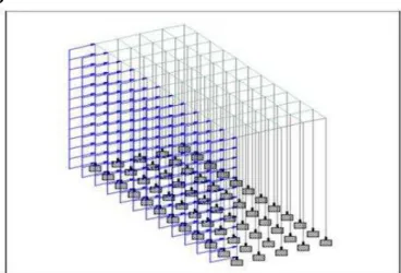
Fig: 4.1.7 Lateral load representation on structure
Design seismic base shear VB= AhW
Ah = horizontal seismic coefficient
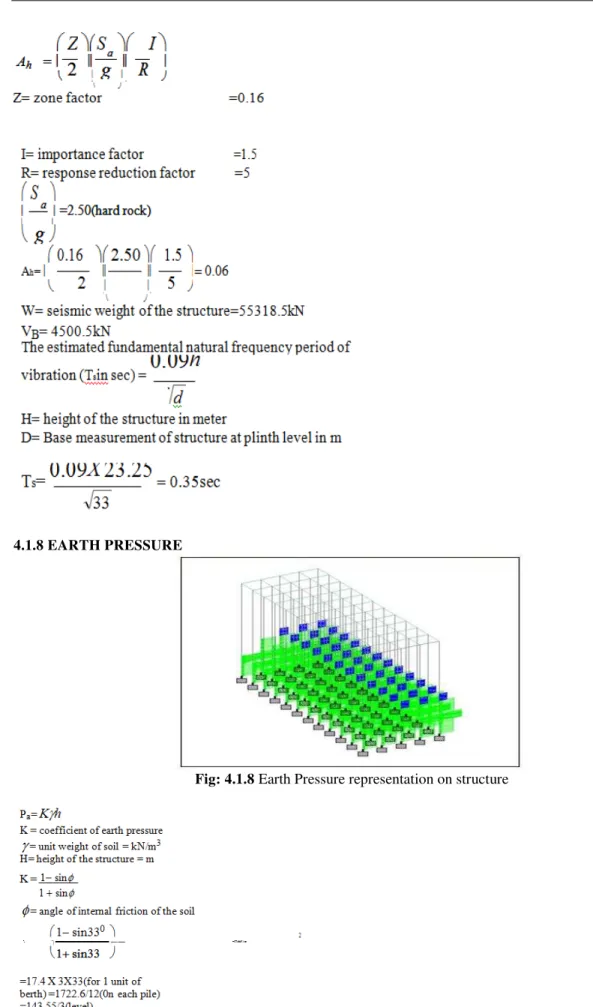
4.1.8 EARTH PRESSURE
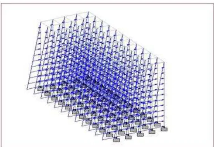
4.1.9 HYDROSTATIC PRESSURE
On account of waterfront structures with inlay, the weight created by distinction in water level at the fill side and waterside must be considered in design configuration. The magnitude of hydrostatic pressure is affected by the tidal extent, free water variances, the ground water deluge, the porousness of the establishment of foundation soil and the structure and also the proficiency of accessible refill drainage
Fig: 4.1.9 hydrostatic load representation on structure
P= h
=unit weight of water=10kN/m3
H= water head on structure; m P=10 X 18 =180kN/m2 =180X1.57=270kN/m on every pile
BASIC LOAD COMBINATIONS
1.5DL+1.5LL+1(EARTHPRESSURE)+1(HY
DROSTATICPRESSURE)+1.5(BERTHING LOAD)+1.5(MOORING LOAD)
1.2DL+1.2LL+1E.P+1.2H.P
1.2DL+1.2LL+1EP+1HP+1.5(WIND LOAD)
1.2DL+1.2LL+EP+1HP+1.5(SEISMIC
LOAD)
5.DESIGN
5.1DESIGN OF BEAM
TRANSVERSE BEAM
Pile cap beam
Grade of concrete:M40
Grade of steel:Fe415
Size of the bar:32mm
Spacing between bars:238mm
Cover:50mm
LONGITUDUNAL BEAM
Grade of concrete:M30
Grade of steel:Fe415
Size of the bar:20mm
Spacing between bars:125mm
Cover:50mm
Shear reinforcement:12mm@150mm/cc
5.2DESIGN OF SLAB
Thickness of slab:300mm
Effective depth:217mm
Effective cover:75mm
Grade of concrete:M40
Grade of steel:Fe415
5.3DESIGN OF PILE
Grade of concrete:M40
Grade of steel:Fe415
Dia of the pile:1700mm
Size of bar:40mm
Spacing between bars:76mm
Cover:50mm
Tie reinforcement:16mm@300mm/cc
V.
CONCLUSION
Different factors are to be considered while analyzing and designing the berthing structure. Lateral loads on the berthing structures are more eminent than those on land– based structures. Congruous environmental data, traffic forecasting and soil data ought to be received from the proposed site location, typical load distribution is induced on the shore line structures, so need to utilize STAAD Pro software for the analysis and design.
The structure was analyzed and designed satisfying various loading conditions and dimension analysis for economical aspect was additionally taken care of without exceeding the structural safety. Afore going for designing or orchestrating a berthing structure, all the present and future optimistic conditions regarding traffic data, hinterland expansion and industrialization of that particular hinterland are to be studied, which additionally play a major role in shaping the project inception at the first place.
REFERENCES
[1]. Krishna Raju.N, “Advanced Reinforced Concrete Design”,2ndEdition, Cbs Publication & Distributors Pvt .Ltd, Newdelhi, 2012.
[2]. Muthukkumaran.K, Sundaravadivelu and Gandhi.S.R, “Effect of Dredging and Axial Load on a Berthing Structure”,Geotechnical conference, 2006.
[3]. Premalatha P.V, Muthukkumaran. K & Jayabalan
[4]. P,“Behaviour of piles supported berthing structure underlateral loads”, Geotechnical conference, 2011. [5]. Ramamrutham.S, “Design of Reinforced Concrete Structures”, 16thEdition, Dhanpat Rai Publications
Company, Newdelhi, 2009.
[6]. Sanil Kuma.R, K. Ashok Kumar and N. S. N. Raju, “Wave characteristics off Visakhapatnam coast
during a cyclone “, research article 1524 current science, 2004, vol. 86, no. 11 [7]. Shanthal. B, Subba rao,katta Henkatramana And
[8]. Harish, “ Analysisof berthingstructures for wave induced Forces”,
International journal of earth sciencesand engineering,2011,vol. 4,No 1, pp. 112-121.
[9]. SP16,“Code Of Practice Criteria ForDesign Aids For Reinforced Concrete To IS: 456-2000”, Fourth Revision,Bureau of Indian Standards, New Delhi.
[10]. Thomos dawson. H, “Offshore Structural Engineering”, 2nd Edition, Prentice –hall, New Jersey, 2010 [11]. Thandava Moorty, T.S, “Analysis of Structures”, 6th Edition, Oxford University Press, Newdelhi, 2005.
[12]. www.vizagport.com
[13]. Kavitha.P.E, Dr.Narayanan.K.P, Dr. Sudheer.C.B., “Software Development for the Analysis and Design of ShipBerthing Structures”, ACEEE Int. J. On Transportation and Urban Development, 2011, Vol.1, No. 1.
[14]. Yasser E. Mostafa, “Design Considerations for PileGroups Supporting Marine Structures with Respect to Scour”,(http://www.scirp.org/journal/eng), 2012, No 4,pp.833-842.
[17]. IS: 875 (Part 1) –1987, “Code of Practice for DesignLoads (Other than Earthquake) For Buildings and Structures Part 1 Dead Loads — Unit Weights Of Building Materials and Stored Material”, Second Revision, Bureauof Indian Standards, New Delhi.
[18]. Structures Part 5 Special Loads and Combinations”, Second Revision, Bureau of Indian Standards, New Delhi.
[19]. IS: 875 (Part 2) –1987, “Code of Practice for DesignLoads (Other Than Earthquake) For Buildings and Structures Part 2 Imposed Loads", Second Revision, Bureau of Indian Standards, New Delhi.
[20]. IS: 875 (Part 3) – 1987,”Code of Practice for DesignLoads (Other Than Earthquake) For Buildings and
[21]. Structures Part 3 Wind Loads”, Second Revision, Bureauof Indian Standards, New Delhi.
[22]. IS: 875 (Part 5) –1997, “Code of Practice for DesignLoads (Other Than Earthquake) for Buildings and Structures Part 5 Special Loads and Combinations”,
[23]. Second Revision, Bureau of Indian Standards, New Delhi. [24]. IS: 1893-1984, “Code of Practice Criteria for
[25]. Earthquake Resistant Design of Structures”, Fourth Revision, Bureau of Indian Standards, New Delhi.
[26]. IS 4651 (Part IV): 1989, “Code of Practice for General Design Considerations”, Second Revision, Bureauof Indian Standards, New Delhi.
[27]. IS: 4851 (Part III) – 1974, “Code Of Practice ForPlanning and Design Of Ports and Harbours “,First Revision, Bureau of Indian Standards, New Delhi.