AS SESS MENT OF THREE TUR BU LENCE MODEL
PER FOR MANCES IN PRE DICT ING WA TER JET FLOW
PLUNG ING INTO A LIQ UID POOL
by
Faiza ZIDOUNI KENDIL1, Anis BOUSBIA SALAH 2*, and Amina MATAOUI 3
1
Nu clear Re search Cen ter of Brine, COMENA, Ain Oussera, Djelfa, Al ge ria 2
De part ment of Me chan i cal and Nu clear En gi neer ing, Uni ver sity of Pisa, Pisa, It aly 3
The o ret i cal and Ap plied Fluid Me chan ics Lab o ra tory, Fac ulty of Phys ics, USTHB Al giers, Al ge ria
Sci en tific pa per UDC: 532.529:517.95 DOI: 10.2298/NTRP1001013Z
The main pur pose of the cur rent study is to nu mer i cally in ves ti gate, through com pu ta tional fluid dy nam ics mod el ing, a wa ter jet in jected ver ti cally down ward through a straight cir cu lar pipe into a wa ter bath. The study also aims to ob tain a better un der stand ing of jet be hav ior, air en train ment and the dis per sion of bub bles in the de vel op ing flow re gion. For these pur poses, three di men sional air and wa ter flows were mod eled us ing the vol ume of fluid tech nique. The equa tions in ques tion were for mu lated us ing the den sity and vis cos ity of a “gasliq uid mix -ture”, de scribed in terms of the phase vol ume frac tion.
Three tur bu lence mod els with a high Reynolds num ber have been con sid ered i. e. the stan dard k-e model, re al iz able k-e model, and Reynolds stress model. The pre dicted flow pat terns for the re al iz able k-e model match well with ex per i men tal mea sure ments found in avail able lit er a ture. Nev er the less, some dis crep an cies re gard ing ve loc ity re lax ation and tur bu lent mo men -tum dis tri bu tion in the pool are still ob served for both the stan dard k-eand the Reynolds stress model.
Key words: wa ter jet, tur bu lence mod el ing, VOF model, re al iz able k-e model, Reynolds stress model, stan dard k-e model
INTRODUCTION
Ad vanced com pu ta tional meth ods, such as com pu ta tional fluid dy nam ics (CFD), have now been rec og nized as im por tant tools that al low de tailed mod el -ing, un der sin gle and two-phase flows, of the ve loc ity, pres sure and tem per a ture fields with a high de gree of ac cu racy. An im por tant and chal leng ing as pect con -cerns liq uid in jected into a gas eous me dium. Such phe nom e non is a cru cial mat ter in many in dus trial top -ics rang ing from ink-jet print ing, di rect fuel in jec tion in die sel en gines, min er als-pro cess ing floa ta tion cells, to emer gency core cool ing of a pres sur ized wa ter nu -clear re ac tor.
CFD mod el ing is con sid ered here af ter, since it al lows use ful in sight into highly com plex flows in the jet ting sys tem. In deed, when a plung ing jet im pinges into a liq uid pool, air bub ble en train ment will oc cur in
the form of a lo cal, sin gu lar aer a tion [1, 2]. The mech a -nisms of bub ble en train ment de pends upon jet ve loc ity at the im pact, phys i cal prop er ties of the fluid, jet noz zle de sign, length of the freefall ing jet and jet tur bu -lence [1]. For small jet ve loc i ties larger than the thresh old ve loc ity, so called on set ve loc ity, air is en -trained in the form of in di vid ual air bub bles. At larger jet ve loc i ties, large pack ets of air are en trained and sub se quently bro ken up in the shear flow.
tri bu tions in the vi cin ity of the im pinge ment point and en trained bub ble size dis tri bu tions. How ever, phys i cal mod el ing of plung ing jet flows re mains sub ject to scal ing ef fects which have not been prop erly ex -plained as of yet [2, 7].
Shakouchi et al. [8] have in ves ti gated ver ti cal wa ter jet plung ing into a wa ter pool and re ported three types of bub ble dis per sion pat terns in cases where the plung ing wa ter jet im pacts the bath sur face be fore its breakup, as shown sche mat i cally in fig. 1. When the dis tance from the pipe exit to the un dis turbed bath sur -face is short, and ac cord ingly, the sur -face of the wa ter jet is smooth, a lot of small bub bles are gen er ated and they dis perse through out the bath (type 1).
On the other hand, when the dis tance is long and the sur face of the wa ter rough, rel a tively large bub bles are gen er ated and the bub ble dis per sion re gion is lo cal ized be neath the pipe exit (type 3). Bub ble dis per -sion pat terns of type 1 and 3 ap pear si mul ta neously for the in ter me di ate dis tance (type 2). Ex act knowl edge of the bound aries among these three re gimes has, how -ever, not been ob tained. As op posed to this, tur bu lence char ac ter is tics in bub bly flows in duced by a plung ing wa ter jet into a wa ter bath are well doc u mented.
Iguchi et al. [9] re cap tured ex per i ments with the same flow field and de duced that bub ble en train ment is mainly re lated to shear flow in sta bil i ties on the plung ing jet sur face. Ad di tional tur bu lence pro duc tion in the wake of bub bles also af fects the de vel op -ment of the flow in the wa ter bath. More in for ma tion on these char ac ter is tics would be use ful for the pur -pose of this study.
In fact, this work in ves ti gates ap pro pri ate tur bu lence mod els for sim u lat ing a ver ti cal wa ter jet plung ing into a wa ter pool. The as sess ment is per formed us -ing three tur bu lence mod els: the stan dard k-e, re al iz able k-e, and the Reynolds stress model. This is fol lowed by com par a tive stud ies of the sim u la tion re -sults and ex per i men tal mea sure ments by Iguchi et al. [9].
In the plung ing jet con fig u ra tion, gas has two dif fer ent morphologies (see fig. 2). The gas above the wa ter level is a con tin u ous phase, whereas the gas be -low the wa ter level is the dis persed phase. In or der to model this flow, two ap proaches are pos si ble. The one us ing the Eu ler-Eu ler method with two phases: one for
wa ter (con tin u ous phase) and the other for the gas (dis -persed phase). The dif fer ent morphologies of the gas then have to be re flected by dif fer ent co ef fi cients in clo sures for the mo men tum trans fer be tween the gas and wa ter phases. In the sec ond ap proach, one can use only one ho mo ge neous phase with a sur face re con -struc tion. This model is rec om mended for strat i fied or non-inter pen etrat ing flows. In this ap proach, the morphologies of the gas have to be re con structed us -ing the re con sti tu tion of the in ter face al go rithm which rep re sents the free sur face (air wa ter) as a sharp dis con ti nu ity. Since gas and liq uid flows do not inter pen -etrate in the con sid ered cases, a cal cu la tion with the vol ume of fluid (VOF) ap proach has been cho sen. The VOF model en ables the com pu ta tion of two-phase flows where the phases do not mix, so the gas-liq uid in ter face is clearly iden ti fied.
MAIN CONSERVATION EQUATIONS
In this sim u la tion, the gov ern ing equa tions in the three di men sional co or di nate sys tems are solved us ing the com mer cial CFD code FLU ENT.
The jet ting sys tem con sid ered herein is gov -erned by gas and liq uid flows and, as stated in the afore men tioned para graph, can be mod eled us ing the VOF tech nique (Hirt et al.) [11]. The lat ter is based upon the fixed grid tech nique de signed for two or more im mis ci ble flu ids (or phases), where the po si tion of the in ter face is of the ut most in ter est.
Fig ure 1. Three types of bub ble dis per sion pat terns [8]
Mass equation
In the VOF model, the vol ume frac tion of each of the phases in each com pu ta tional cell is tracked through out the com pu ta tional do main. In ad di tion to the ve loc ity and pres sure, vol ume frac tion is also a vari able of the flow field in the VOF tech nique and, hence, con tained in both mass and mo men tum equa -tions.
The con ti nu ity equa tion for the liq uid (pri mary phase) with a vol ume frac tion j, has the fol low ing form ¶ ¶ j j t u
+ div =0 (1)
where the sec ond ary phase vol ume frac tion is
jg = -1 j (2)
and the prop er ties of these phases are de fined as
r=rg(1-j)+r jl (3)
m=mg(1-j)+m jl (4)
Momentum equation
The mo men tum equa tion for the com pu ta tional do main in its gen er al ized form can be writ ten as
¶ ¶ r r m r u
t u p
+div = -grad +
+ div [grad(u)] + g
( ) (5)
where g is the ac cel er a tion due to grav ity, p – the fluid pres sure, r and µ are the den sity and vis cos ity based on eqs. (3) and (4), re spec tively.
Turbulent flow equations
Since the liq uid and gas ve loc ity ex it ing the noz -zles is rel a tively high, it is ap pro pri ate to sim u late the flow in the jet ting sys tem us ing a tur bu lent flow model. To do this, the flow vari ables, such as that of f, and fluc tu a tion f¢, cor re spond in a stan dard way, so that: f = f + f¢. In sert ing the de com posed vari ables to the in stan ta neous equa tion and ap ply ing the Reynolds av er ag ing, yield a set of Reynolds av er aged con ser va -tion equa -tions for mass and mo men tum, as well as for tur bu lence ki netic en ergy, k, and its dis si pa tion rate e. For con ve nience, and in or der to drop over bear on the mean vari ables, the Reynolds av er aged equa tion can be writ ten in the fol low ing ge neric trans port equa tion form ¶ ¶ ¶ ¶ ¶ ¶ ¶ 
t k x ku
x
k x
(r ) (r )
m m s
+ =
= æ +
è çç ö ø ÷÷ é ë ê ù û ú + i i
j k j
t
Gk+Gb-re-YM+Sk (6)
¶ ¶ ¶ ¶ ¶ ¶ ¶ 
t x x x
C
i i
t
k j
(re) (re) = m m s
e
+ æ +
è çç ö ø ÷÷ é ë ê ù û ú + +
1e e e e
e
re k(Gk C Gb) C k S
+ - +
3 2
2
(7)
where Gk is the gen er a tion of ki netic en ergy of the tur
-bu lence due to mean ve loc ity gra di ents, Gb – the gen er
-a tion of ki netic en ergy of tur bu lence due to buoy -ancy, Yk rep re sents the con tri bu tion of the fluc tu at ing di la ta
tion in com press ible tur bu lence to the over all dis si pa -tion rate, C1e, C2e, and C3e are con stants, sk and se are the
tur bu lent Prandtl num bers for k and s, re spec tively, and Sk and Se are the user-de fined source terms.
CLOSURE EQUATIONS
The so lu tions of con ser va tion equa tions are ob -tained through the fol low ing clo sure re la tions.
Standard energy dissipation model
Tur bu lent (or eddy) vis cos ity, µt, is com puted by com bin ing k and e as fol lows
m r
e t = C
k m
2
(8)
where Cµ is a con stant, while model con stants C1e, C2e, Cµ, sk, and se have the fol low ing de fault val ues: C1e = = 1.44, C2e =1.92, Cµ = 0.09, sk = 1.0, se = 1.3
These de fault val ues have been de ter mined from ex per i ments with air and wa ter for fun da men tal tur bu -lent shear flows, in clud ing ho mo ge neous shear flows and de cay ing iso tro pic grid tur bu lence. They have been found to work fairly well for a wide range of wall-bounded and free shear flows.
Realizable k-e turbulence model
The re al iz able k-e model is a rel a tively re cent de -vel op ment, dif fer ing from the stan dard k-e model in two cru cial ways:
– the re al iz able k-e model con tains a new for mu la -tion of tur bu lent vis cos ity, and
– a new trans port equa tion for the dis si pa tion rate e has been de rived from an ex act equa tion for the trans port of the mean-square vor ti ces fluc tu a tion.
The s re al iz able k-e model con sid ers the com bi na tion of the Boussinesq re la tion ship and the eddy vis -cos ity def i ni tion to ob tain the fol low ing ex pres sion for the nor mal Reynolds stress in an in com press ible strained mean flow
u k U
x 2 2
3 2
= - ut
¶ (9)
us ing eq. (8), for cal cu lat ing ut = µt /r, it can be ob
-tained that the nor mal stress, u2 which by def i ni tion is
a pos i tive quan tity, be comes neg a tive, i. e., “nonre al -iz able“, when the strain is large enough to sat isfy
k U
x C
e 
¶ m
> 1 »
3 3 7. (10)
Sim i larly, it can also be shown that the Schwarz in equal ity for shear stresses (u ua b u ua b)
2£ 2 2
no sum -ma tion over a and b) can be vi o lated when the mean strain rate is large.
The most straight for ward way to en sure the realizability (positivity of nor mal stresses and Schwarz in equal ity for shear stresses) is to make Cµ vari able by sen si tiz ing it to the mean flow (mean de -for ma tion) and the tur bu lence k-e as de scribe be low
C
A A U
m = + 1 0 s k * e where ~ ~ ~ * W W
W W W W
ij ij
ij ij ijk k
ij ij ij ij
=
-= - º +
2e w e w
ijk k
U S S
where Wij is the mean rate-of-ro ta tion ten sor viewed in a ro tat ing ref er ence frame with the an gu lar ve loc ity wk. Model con stants A0 and As are given by
A0 = 4.04 and As= 6 cosf
f=1 - = =
3 6
1
3
cos W W, S S S~ ,~
S S S S
jk ki ij ij ij , where S u x u x ij j i i j
= æ +
è ç ç ö ø ÷ ÷ 1 2 ¶ ¶ ¶ 
In CFD FLU ENT com pu ta tion, the term –2eijkwk is, by de fault, not in cluded in the cal cu la tion of W~ij. This is an ex tra ro ta tion term that is not com pat i ble with cases in volv ing slid ing meshes or mul ti ple ref er -ence frames.
Transport equations for the realizable k-e model
The mod eled trans port equa tions for k and e in the re al iz able k-e model are
¶ ¶ ¶ ¶ ¶ ¶ + ¶ 
t k x ku
x k x j j i j
(r ) (r )
m m s + = = æ è çç ö ø ÷÷ é ë ê ù û ú + t k
Gk+Gb-re-YM+Sk (11)
¶ ¶ ¶ ¶ ¶ ¶ ¶ 
t xj u x x
j
j j
(re) (re ) m m
s e
r
e
+ = æ +
è çç ö ø ÷÷ é ë ê ù û ú t
+ C1S C b
k C kC G S
e r e e e
e ue e -+ + + + 2 2
1 3 (12)
where C1=max [ .0 43,h h( +5)],h=S k( e), and the mean rate-of-strain ten sor S =( S Sij ij)
/
2 1 2
.
Model con stants C2, sk, and se have been es tab lished to en sure that the model per forms well for cer -tain ca non i cal flows. The model con stants are C1e = =.1.44, C2 = 1.9, sk = 1.0, se =1.2.
Reynolds stress turbulence model
In gen eral, when the tur bu lence ki netic en ergy is needed for mod el ing a spe cific term, it is ob tained by tak ing the trace of the Reynolds stress ten sor
k= u u¢ ¢i i 1
2 (13)
The ex act trans port equa tions for the trans port of Reynolds stresses, ru u¢ ¢i j, may be writ ten as fol lows
¶ 
¶ ¶ t u ui j x u u
k k i
( ) (
local time derivation
¢ ¢ + ¢ ¢
1 24 43
r u
x u u u p u
j
C ij
k
i j k kj i ) [ ( convection º = - ¢ ¢ ¢ + ¢ +
14243
¶ r d dik j
D T,ij u¢ º + )]
turbulent diffusion
14 4 4 4424 4 4 4 43
¶x x ( u u )
k k i j DL,ij m ¶ ¶ ¢ ¢ é ë ê ù û ú
º molecular diffusion
14 424 43
- æ ¢ ¢ + ¢ ¢
è
çç ö
ø ÷÷
-º
r u u u
x u u u x j k j k j k j k Pij ¶ ¶ ¶ 
stress production
buoy
(g )
14 4 424 4 43
- ¢ + ¢
º
rb i iq j i Gij
u g u q
ancy production
14 424 43
+ æ ¢+ ¢
è ç ç ö ø ÷ ÷ p u x u x i j j i fij ¶ ¶ ¶ ¶ º
- æ ¢ ¢
è çç ö ø ÷÷ u x u x i k j k e pressure strain
1442443
2m ¶ 
ij
k j m ikm i m jkm F
u u u u
º
-- ¢ ¢ + ¢ ¢
dissipation
( )
14243
2rW e e
ij
S
º
+
production by system rotation us
14 4 4424 4 443
ersss
source term
123 (14)
Con vec tion term Cij, mo lec u lar dif fu sion DL,ij, stress pro duc tion, Pij, and pro duc tion by sys tem ro ta -tion term Fij, do not re quire mod el ing, but other terms
need mod el ing in or der to close a sys tem of dif fer en tial equa tions. The dis si pa tion ten sor, eij, is mod eled as
eij = dij re+Y 2
3 ( M) (15)
where YM =2 Mt 2
re is an ad di tional “di la ta tion dis si -pa tion”.
The tur bu lent Mach num ber in this term is de -fined as: Mt =( /k a )
/ 2 1 2
The sca lar dis si pa tion rate e is com puted with a model trans port equa tion sim i lar to that used in the stan dard k-e model
¶ 
¶ 
¶ 
¶ 
t xi u x x
i j
t
j
(re) (re ) m m
s e
e
+ = æ +
è
çç ö
ø ÷÷ é
ë
ê ù
û ú +
+C P C G
k C k S
ii ii
e e e e
e
r e
1 3 2
2
1
2[ + ] - + (16)
where se = 1.0, C1e = 1.44, Ce2 = 1.92, Ce3 is eval u ated
as a func tion of the lo cal flow di rec tion rel a tive to the grav i ta tional vec tor, and Se is a user-de fined source term, not con sid ered in this study.
Tur bu lent vis cos ity, µt, is com puted in the same man ner as in k-e mod els, ac cord ing to eq. (8) with Cµ = 0.09.
COM PU TA TIONAL MOD EL ING PA RAM E TERS
Mod el ing pa ram e ters
Fig ure 3 pro vides a schema of the ex per i men tal ap pa ra tus re fer ring to Iguchi et al. [9] and McKeogh et al. [4]. The ves sel has an in ner di am e ter (D) of 20.0 cm, while the ves sel di am e ter is 20 cm with a height (H) of 39.0 cm. The or i gin of the cy lin dri cal co or di -nate sys tem is placed on the un dis turbed bath sur face. Ax ial and ra dial co or di nates are de noted by z and r, re -spec tively. The cor re spond ing ve loc ity com po nents were des ig nated by u and v. The wa ter is in jected through a straight cir cu lar pipe (hav ing an in ner di am -e t-er d of 0.5 cm and a length L of 60 cm) into a wa ter
bath. The plung ing wa ter jet im pinges per pen dic u larly to the wa ter sur face.
The in let con di tions were also de ter mined by con sult ing the pre vi ous in ves ti ga tors [4, 9]. The plung ing wa ter jet flow rate Qw is 50 cm3/s. The cor re -spond ing mean pipe exit ve loc ity at u0 (= 4 Qw/pd2) is 254 cm/s.
The pipe Reynolds num ber is higher than 104 and the re spec tive ra tio L/d is 120. Ac cord ingly, the wa ter flow in the pipe is tur bu lent and fully de vel oped at the pipe exit. At the lo ca tion, tur bu lence in ten sity in -creased monotonically from ap prox i mately 5% in the cen tral part, to ap prox i mately 15% in the outer part of the pipe. These tur bu lence in ten si ties are de scribed here be cause they af fect the be hav ior of the bub bles sig nif i cantly [1].
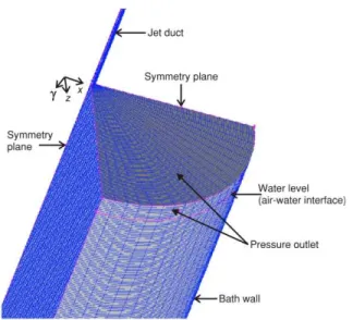
Ge om e try and grid ar range ment
The ge om e try and com pu ta tional do main used to model the jet ting sys tem are shown in fig. 4. The sym -me try of the con fig u ra tion al lowed us to con sider a quar ter do main for the com pu ta tion. A threedi men -sional com pu ta tional do main is con sid ered us ing a non-uni form mesh ing grid by the tet ra he dral scheme; with this scheme, clus ter ing is au to mat i cally made to -wards the cen ter line of the wa ter jet di rec tion. Grid con trac tion to ward the free sur face is re quired for cap -tur ing the gas and liq uid flows and the de for ma tion of the gas-liq uid in ter face.
The un cer tainty in nu mer i cal re sults is as sessed by check ing the con ver gence through mesh re fine ment cal cu la tions for sim u la tions of two plung ing wa
ter jet con fig u ra tions. For this pur pose, the fol low ing cases were com puted for: (a) dxi = 0.4 mm; (b) dxi= =.0.223 mm; (c) dxi = 0.2 mm. The re sults are af ter
-wards com pared for con tours j at var i ous sim u la tion times in the cen ter line ve loc ity pro file. Cal cu la tions show that the mesh sizes used in case (b) were ad e quate for this kind of jet sim u la tions, since no dif fer -ence was noted when com pared with case (c). Fur ther mesh re fine ment and nu mer i cal tests were car ried out to check the sta bil ity of the plung ing jet flow sim u la -tion.
The po si tion of the sur face of the liq uid is es ti -mated by plot ting con tours of equal value to the air vol ume frac tion j. The value of j =10–4 is used to de -ter mine the po si tion of the jet in -ter face. Time step dt, is set by con sid er ing the max i mum at tain able ve loc ity v of the fluid in one di rec tion (xi). It is lim ited by the
Cou rant num ber, dt/(dx/u) < 0.25. For most sim u la -tions re ported here, dt is fixed at 1×10⁻⁵ s.
The used spa tial discretisation was per formed by the QUICK in ter po la tion scheme, while the higheror -der dif fer ences scheme is used for time step ping. The un der-re lax ation pa ram e ters for pres sure and ve loc ity are usu ally set to a value of 0.2.
Bound ary conditions
Four types of bound ary con di tions were used to pre dict the flow field within the com pu ta tional do main.
Wa ter jet in let
The con di tion of the noz zle is im por tant in pre -dict ing cen ter line ve loc ity and shear stress. In this work, a uni form ve loc ity pro file is con sid ered. The im posed in let ve loc ity bound ary con di tions at the noz -zle are ex pressed by
U U
V W
k k U I
=
= =
= =
= =
inlet
inlet inlet
inlet
and ,
. ( )
(
0 0
15 2
e e C k
I m)
( )
/
/ 3 4
3 2 inlet
where the tur bu lence length scale at the in let is as -sumed to be the noz zle open ing. Tur bu lence in ten sity, I, is as sumed to be 10% of the mean in let ve loc ity mag -ni tude.
Solid bound aries
Wall bound ary con di tions are used at the solid bound ary of the liq uid pool where no slip bound ary con di tions were im posed. For the eval u a tion of the wall ef fect on tur bu lence, the log a rith mic near wall func tion ap proach [12] has been used to model the wall bounded tur bu lent flows. The semi em pir i cal for mula is used to bridge the ve loc ity af fected re gion (vis -cous sub layer and buffer layer) be tween the wall and the fully tur bu lent re gion.
Exit bound aries
The exit wa ter bound ary con sid ers a non-fully de vel oped flow. In fact, it is found that re versed flows can oc cur at this bound ary, in di cat ing that the fluid mo tion is not fully de vel oped. Con se quently, the pres -sure out let bound ary is as sumed.
Sym me try
Sym me try bound aries are used to re duce the com -pu ta tional do main to a sym met ric sub sec tion of the over all phys i cal sys tem. The nor mal gra di ents of all flow vari ables are thus zero at the sym me try plane. The sym me try bound ary con di tion can there fore be sum ma -rized as:
– zero nor mal ve loc ity at a sym me try plane, and – zero nor mal gra di ents of all vari ables at a sym me
-try plane.
RE SULTS AND DIS CUS SION
In gen eral, af ter about 10 s of the sim u lated phys i cal time, the tran sient VOF-RANS cal cu la tions be come steady. For a good ac cu racy of the sim u lated flow, the times step is rel a tively small (Dt = 10–5).
Bub ble be hav ior
The agree ment be tween the ex per i ment and the sim u la tion is quite good for con fig u ra tion (b). For con fig u ra tion (a), the bub bles at tain the bot tom of the wall. This dis crep ancy from the ex per i men tal ob ser va -tion can be ex plained as fol lows: when cells, mainly large cells, con tain more than one bub ble, the reconstitutive interf
ace method can not re con sti tute them in di vid u -ally, col laps ing them in stead in one larger bub ble. The pos si ble so lu tion is to adopt smaller cells in this re -gion, but in this case, the com pu ta tional time be comes ex tremely large.
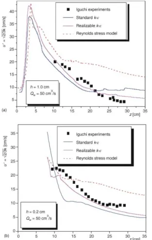
Dis tri bu tion of the ax ial mean
ve loc ity of the bub ble dis per sion re gion
Look ing at the ax ial ve loc ity pro file in fig. 6(a) and 6(b) cor re spond ing to con fig u ra tions where h = 1 cm and h = 0.2 cm, re spec tively, it can be said that no stan -dard k-e model or Reynolds stress model matches ac cu -rately the ex per i men tal data.
The re al iz able k-e tur bu lence model pre dicts the ve loc ity pro file for the two con fig u ra tions much better. Some dis crep an cies ap pear at a deeper dis tance (z > 15cm) for the con fig u ra tion where h = 1cm. This is ex plained as fol lows: the max i mum bub ble di am e ter for h = 1 cm is much larger than that of h = 0.2 cm,
Fig ure 5. Air bub bles be hav ior when jet im pinges the ves sel jjjjjj(a) wa ter jet con fig u ra tion h = 1 cm; (b): wa ter jet con fig u ra tion h = 0.2 cm
thus the buoy ancy forces play a more im por tant role for h = 1 cm than for h = 0.2 cm. As a re sult, the down -ward wa ter mo tion for h = 1 cm (flow type 3 in fig. 3) is highly sup pressed for z > 15 cm. To elim i nate such dis -crep an cies, an elab o rated two-phase flow model can be pro posed with a re al iz able k-e model.
Tur bu lence com po nents on the
cen ter line of the bub ble dis per sion re gion
In figs. 7(a) and 7(b), the stan dard k-e model slightly un der-pre dicts the tur bu lence ki netic en ergy, while the Reynolds stress model’s pre dic tion is much higher. The re al iz able k-e model is found to per form and model this flow char ac ter is tic much better than the stan dard k-e.
Re gard ing the Reynolds stress model, the re sults are fairly un ex pected, be cause this model is de signed so as to pre dict more com plex flows, such as anisotropic flows with strong cur va tures. This can be at trib uted to the lim i ta tion of the ho mog e nous-VOF model. In fact, this model uses a lot of as sump tions, such as the one of a sin gle ve loc ity for air and wa ter, ne glect ing the buoy ancy ef fect and the ad di tional tur bu lence added by the mi gra tion of bub bles. Nev er the
-less, fur ther in ves ti ga tions us ing more elab o rate and so phis ti cated mod els are needed.
Tur bu lent ki netic en ergy con tours
As stated in the ex per i men tal ob ser va tions of Iguchi et al. [9], the flow con fig u ra tion for h = 1 cm (Qw = 50 cm3/s) cor re sponds to flow type 3 and that of h = 0.2 cm (Qw = 50 cm3/s) cor re sponds to flow type 1 in fig. 3.
Ac cord ing to these ex per i men tal ob ser va tions, we can as sume that the ki netic en ergy con tours for these two con fig u ra tions (h = 1 cm and h = 0.2 cm) are as ex pected. The lo cal max ima of ki netic en ergy cor re sponds, more or less, to the two lat eral ed dies on each side of the jet.
For flow pat tern type 3, rel a tively large bub bles are gen er ated and the bub ble dis per sion re gion is lo -cal ized be neath the pipe exit; for this rea son, the shear layer is close to the jet axis as ob served in fig. 8(a), cor -re spond ing to the max i mum ki netic en ergy.
But, for the flow pat tern type 1, a num ber of small bub bles are gen er ated and they dis perse in the bath, so the shear layer is slightly off the jet axis which makes the max i mum ki netic en ergy max i mum lo cated around the jet axis (see fig. 8b), cor re spond ing to the con fig u ra tion h = 0.2 cm.
CON CLUD ING RE MARKS
Now a days, multi-di men sional mod el ing of flows is be ing in ten sively in ves ti gated in or der to ob tain more ac cu rate sim u la tions of com plex phe nom
Fig ure 7. Ve loc ity fluc tu a tion on the cen ter line jjjjjjjjjjjjjj(a) wa ter jet con fig u ra tion h = 1 cm; (b) wa ter jet con fig u ra tion h = 0.2 cm
Fig ure 8. Tur bu lence en ergy con tours in the wa ter bath for the two flow con fig u ra tions
ena en coun tered in the in dus try [13]. In this pa per, a par tic u lar phe nom e non re lated to a ver ti cal in jec tion of wa ter down ward onto a wa ter bath through a cir cu -lar pipe is sim u lated nu mer i cally us ing the com mer cial CFD code FLU ENT based on the VOF tech nique. Three high Reynolds num ber tur bu lence mod els have been con sid ered: the stan dard k-e model, re al iz able k-e model, and Reynolds Stress model.
The re sults can be sum ma rized as fol lows. · Ac cord ing to the ex per i men tal re sults of the flow
pat terns ob served by Shakouchi et al. [4] and Iguchi et al. [9], the ki netic en ergy con tours for these two con fig u ra tions (h = 1 cm, and h = =.0.2 cm with Qw = 50 cm3/s) are as ex pected.
· The re al iz able k-e model is found to be more ac -cu rate than the stan dard k-e and Reynolds Stress model in pre dict ing the cen ter line ve loc ity pro -file. The dis crep an cies ob served for h = 1 cm at z > 15 cm are due to the buoy ancy ef fect which is not well cap tured in this sim u la tion. So as to avoid this prob lem, the other two phase mod els can be pro posed in fur ther work.
The cen ter line ki netic en ergy pro file is over pre -dicted by the Reynolds stress model and slightly un der pre dicted by both stan dard and re al iz able k-e mod els. Cal cu lated flow pat terns of the re al iz able k-e model match well with ex per i men tal mea sure ments of Iguchi et al. [9]. The in ad e quacy of the Reynold stress model to de scribe the ve loc ity and tur bu lent ki netic en ergy could be due to the as sump tions of the ho mo ge neous two phase model. Nev er the less, further in ves ti ga tions us ing more elab o rate and so phis ti cated mod els are needed.
NO MEN CLA TURE
D – ves sel di am e ter, [m] d – jet di am e ter, [m] L – duct jet length, [m]
g – acceleration due to grav ity, [ms–2] h – dis tance from the jet exit to the
bath free sur face, [m] u – ax ial mean ve loc ity, [ms–1] l – tur bu lent length scale, [m] p – fluid pres sure, [kgm–1s–1] e – en ergy dis si pa tion rate, [m2s–3] k – tur bu lent ki netic en ergy, [m2s–2] z – ves sel depth co or di nate, [m] Greek let ters
m – vis cos ity, [kgm–1s–1] r – den sity, [kgm–3]
s – in ter fa cial ten sion, [kgm2s–2] F – sca lar vari able, [–]
j – liq uid pri mary-phase vol ume frac tion, [–] Sub scripts
in let – at the in let of the jet
out let – at the out let flow g – rel a tive to the gas (air) l – rel a tive to the liq uid (wa ter)
REF ER ENCES
[1] Bin, A. K., Gas En train ment by Lung ing Liq uid Jets,
Chem i cal. En gi neer ing. Sci ence., 48 (1993), 21, pp. 3585-3630
[2] Chan son, H., Cumming, P. D., Mod el ing Air Bub ble En train ment by Plung ing Break ers, Pro ceed ing, (Eds. M. Isaacson, M. Quick), In ter na tional Sym po sium: Waves – Phys i cal and Nu mer i cal Mod el ing, IAHR, Van cou ver, Can ada, Vol. 2, pp. 783-792, 1994 (ISBN 0-88865-364-6)
[3] Chan son, H., Air Bub ble En train ment in Free-Sur face Tur bu lent Shear Flows, Ac a demic Press, Lon don, UK, 1997
[4] McKeogh, E. J., Ervine, D. A., Air En train ment Rate and Dif fu sion Pat tern of Plung ing Liq uid Jets, Chem i -cal En gi neer ing Sci ence, 36 (1981), 21, pp. 1161–1172
[5] Van de Donk, J., Wa ter Aer a tion with Plung ing Jets, Ph. D. the sis, TH Delft, The Neth er lands, 1981
[6] Bonetto, F., Lahey, R.T. Jr, An Ex per i men tal Study on Air Carryunder due to a Plung ing Liq uid Jet, Intl J. of Multiphase Flow, 19 (1993), 2, pp. 281-294
[7] Wood, I. R., Air En train ment in Free-Sur face Flows, IAHR Hy drau lic Struc tures De sign Man ual No. 4, Hy drau lic De sign Con sid er ations, Balkema, Rot ter -dam, The Neth er lands, 1991
[8] Shakouchi, T., Akita, T., Ota, H. Sato, S., The Flow Char ac ter is tics of Round Wa ter Jet (in Jap a nese), 15th Multiphase Flow Sym po sium 1996, Fukui, Ja pan, pp. 101-104
[9] Iguchi, M., Okita, K., Mean Ve loc ity and Tur bu lence Char ac ter is tics of Wa ter Flow in the Bub ble Dis per -sion Re gion In duced by Plung ing Wa ter Jet, Int. J. Multiphase Flow, 24 (1998), 4, pp. 523-537
[10] Scheuerer, M., Se lec tion of PTS-Rel e vant Test Cases, 5th Euratom Frame Work Programme 1998-2002 – Key ac tion: Nu clear Fis sion
[11] Hirt, C. W., Nichols, S. D., Vol ume of Fluid (VOF) Method for Dy nam ics of Free Bound aries, J. Com pu -ta tional Phys ics., 39 (1981), 1, pp. 201-225
[12] Laun der, B. E., Spalding, D. B., The Nu mer i cal Computation of Tur bu lent Flows, Com puter Meth ods in Ap plied Me chan ics and En gi neer ing, 3 (1974), pp. 269-287
[13] Bousbia Salah, A., Moretti, F., D’Auria, F., State of the Art and Needs for Jet In sta bil i ties and Di rect Con -tact Con den sa tion Model Im prove ments, Nu clear Tech nol ogy and Ra di a tion Pro tec tion, 22 (2007), 1, pp. 58-66
Faiza ZIDUNI KENDIL, Anis BUSBIJA SALAH, Amina MATAUI
PROCENA U^INAKA TRI MODELA TURBULENCIJE ZA PREDVI\AWE TOKA VODENOG MLAZA KOJI URAWA U BAZEN SA TE^NO[]U
Osnovna namera ovog prou~avawa je da ra~unarskim modelovawem dinamike fluida numeri~ki ispita vodeni mlaz ubrizgan kroz pravu cev vertikalno nani`e u bazen sa vodom. Ciq je tako|e, boqe razumevawe pona{awa mlaza, uno{ewa vazduha i disperzije mehurawa u oblasti toka koji se razvija. U ovu svrhu, tehnikom zapremine fluida, trodimenzionalno su modelovani vazdu{ni i vodeni tokovi. Potrebne jedna~ine formulisane su kori{}ewem gustine i viskoznosti “gasno-te~ne me{avine”, opisane pojmovima fazno zapreminske frakcije.
Za dati tok razmatrana su tri modela turbulencije sa velikim Rejnoldsovim brojem: standardni k-e model, ostvarivi k-e model i Rejnoldsov stres model. Predvi|eni obrasci toka po
ostvarivom k-e modelu dobro se sla`u sa eksperimentalnim merewima navedenim u literaturi.
Ipak, neka neslagawa koja se ti~u slabqewa brzine i raspodele momenta turbulencije u bazenu moraju biti spomenuta, i za standardni k-e i za Rejnoldsov stres model.
Kqu~ne re~i: vodeni mlaz, urawawe, modelovawe turbulencije, model zapremine fluida,
![Fig ure 1. Three types of bub ble dis per sion pat terns [8]](https://thumb-eu.123doks.com/thumbv2/123dok_br/16281148.184619/2.894.453.790.107.510/fig-ure-types-bub-ble-dis-sion-terns.webp)
![Fig ure 3. Sche matic of ex per i men tal ap pa ra tus, Iguchi et al. [9]](https://thumb-eu.123doks.com/thumbv2/123dok_br/16281148.184619/5.894.134.760.732.1135/fig-ure-sche-matic-per-men-tal-iguchi.webp)