Received April 2nd, 2009.
Improved Predictive Power Control Algorithms to
Increase CDMA System Capacity
A. Kurniawan, Iskandar & Sayid Machdar
School of Electrical Engineering and Informatics, Bandung Institute of Technology, Jalan Ganesa 10, Bandung 40132, Indonesia
adit@ltrgm.ee.itb.ac.id, http://radar.ee.itb.ac.id
Abstract. In this paper capacity of CDMA system is evaluated using an improved algorithm of channel prediction-based power control in Rayleigh fading channel environments. One of the most serious problems which degrades the performance of power control algorithm is the effect of feedback delay. To overcome the effect of feedback delay, power control algorithm relies on channel prediction techniques, which utilize the correlation property of the past channel measurements. In CDMA power control, however, the correlation property of channel measurements is destroyed because the transmit power is continuously updated for each power control interval. In order to restore the correlation property of the channel, the past channel measurements are compensated for by the same factors that were given by power updating for each power control interval. The prediction algorithm in this paper is proposed using the least mean square (LMS) technique. The result shows that the capacity of CDMA systems increase significantly when the improved predictive algorithm is used. Numerical evaluation shows that CDMA capacity increases by more than 40 % for fixed step algorithm and more than 50 % for variable step algorithm when the proposed algorithm is employed.
Keywords:CDMA; least mean square; power control; prediction; Rayleigh fading.
1
Introduction
CDMA power control is more important on the uplink direction compared to that on the downlink because uplink signals consist of all users from different locations (different path losses), while the downlink signals originate from the same base station and arrive at mobile stations with the same power level. Our previous study [2] shows that practical power control is imperfect in that it is affected by many factors; such as power updating rates and step size, channel estimation error, feedback transmission error, and feedback delay. This paper also shows that the effect of feedback delay on the performance of power control is the most serious. Therefore, prediction-based algorithms are employed to eliminate the effect of feedback delay. In a prediction-based algorithm, the channel state is predicted either through the measurement of signal strength or the signal-to-interference ratio (SIR) as the control parameter for power control algorithms.
Prediction algorithms utilize the correlation property of the past input samples or past measurements in order to predict the future channel conditions. In CDMA power control, however, the correlation property of the channel measurement is destroyed by power control updating, because the received signal strength or the SIR is continuously updated for each power control interval. Therefore, the conventional prediction-based algorithms may not work satisfactorily. In this paper the author proposes an improved prediction-based power control algorithm in that the past input samples to the predictor are compensated for by the same factors that were given by power updating for each power control interval in order to restore the correlation property of the channel.
The rest of the paper is organized as follows. Section 2 presents the closed loop power control algorithm in CDMA systems and explains the feedback delay problem. This section also briefly describes prediction filtering techniques. Section 3 proposes an improved prediction technique for CDMA predictive closed loop power control algorithms. The computer simulation of the proposed algorithm and the results which show the improved capacity of CDMA systems using the proposed technique are discussed and shown in Section 4. Finally, Section 5 draws the conclusion.
2
CDMA Predictive Power Control
2.1
Power Control Algorithm
originate from the same location (base station). These signals will go into the same multipath fading channel, experience the same propagation path loss, and fade simultaneously.
In the uplink, signals from different mobile users are subject to different propagation mechanisms, resulting in different propagation path losses and independent fading that lead to unequal received power levels at the base station. When non-orthogonal spreading sequence of unequal received power levels arrive at the base station, multiple access interference becomes a serious problem [3].
At the base station, the user recovers the transmitted symbol by correlating the received signal with the user spreading sequence. Due to non-zero cross correlation between spreading sequences of different users, the user will observe multiple access interference from the other users. If the received power levels at the base station are not equal, the correlating receiver may not be able
to detect the weak user’s signal due to high interference from other users with
higher power levels. Clearly, if a user is received with a weak power, it will
suffer from the interference generated by stronger users’ signals. Therefore
power control in the uplink is indispensable to keep the interference acceptable to all users and to obtain a considerable channel-capacity [4]. In this paper power control is considered for the uplink CDMA channel based on SIR measurement as shown in Figure 1.
For uplink power control, the mechanism of predictive power control algorithm proceeds as follows. First, the SIR for each user, (i) is measured at the base station for the ith time slot. Due to the feedback delay introduced in the power control loop, the SIR for the ith time slot needs to be predicted D step ahead, where D is the total feedback delay introduced in the loop. Here the feedback loop delay is introduced in the power control algorithm due to measurement time, processing and propagation time of the command bits [5]. Therefore in Figure 1, (i) is predicted using the past SIR measurements to obtained the predicted value of SIR for the ith time slot, pred(i). We skip at this point the
mechanism of SIR predictor to obtain pred(i) using the past input samples
because this part will be explained in more detail in a section that follow. The predicted SIR for the ith time slot pred(i) is then compared with the target SIR t
mode q, where q is the number of PCC bits required in each power control interval.
Figure 1 Predictive power control algorithm
The PCC bits for the ith time slot can be expressed as [6].
2 / 1 2 index ), 1 2 ( 2 / 1 2 index 2 / 3 2 ), 2 2 ( . . . . 2 / 1 index 2 / 1 , 0 . . . . 2 / 3 2 index 2 / 1 2 , 2 2 2 / 1 2 index , 1 2 ) ( 1 1 1 1 1 1 1 1 1 1 q q q q q q q q q q q i
e (1)
Channel variation i Integrator Step size PCC decision
γ(i-D) t
PCC bit error
DTp Loop delay p Tp Transmit
power pi
_ + + + + _ e(i)
MAI from other users
and AWGN
PCC bit
where index is the difference between the predicted SIR ( pred) and the desired
SIR ( t).
The PCC bits are also subject to high bit error rates because they are sent in the downlink channel without using error control coding or interleaving in order to minimize the signaling bandwidth of the downlink channel. Therefore, transmission of the PCC bits on the downlink channel suffers from two major impairments: PCC bit errors and feedback delay. The PCC bits error is represented as a multiplicative disturbance on the PCC bits, while feedback delay is represented by a delay operator of DTp, which represents a multiple
integer D of power control interval Tp as shown on the right hand side of Figure
1. After the PCC bits are received by a mobile station, the mobile station computes the required power adjustment, p x PCC. The step size p is preset at 1 or 2 dB [7], while the PCC is either {+1, -1} in a fixed-step algorithm (q=1) or any integer between –q and +q in a variable-step algorithm.
The difference between the predicted and the desired SIR after quantization e(i)q is sent to the mobile to adjust the mobile’s transmit power by p. e(i)q dB.
Assuming the PCC bits are error free, in the absence of channel predictor, the transmit power at the next interval is
p(i+1) = p(i) - p . e(i-D)q. (2)
For the fixed step algorithm (q=1) the PCC bit can be expressed as
0 D) -(i 1
-0 ) ( 1 ] ) ( [ bit
PCC 1
e D i e D
i e
sign q , (3)
where e(i-D) is the power control error at the (i-D)th power control interval designating DTp loop delay from the ith control interval.
2.2
Effect of Feedback Delay
It has been shown in [8] that the performance of power control in an actual system is limited due to non-ideal parameters of the real system, i.e. loop delay, feedback-channel error, and SIR estimation error. In this paper, feedback channel and SIR measurement are assumed to be error free, so the paper will focus on the effect of feedback delay and propose to use the improved predictor to overcome the effect of feedback delay.
adjusts its transmit power according to the power-control command received from the base station to compensate for the channel. Due to the feedback delay, this power adjustment may no longer correspond to the channel condition when measurements were taken because the channel condition can change rapidly, particularly when Doppler frequency increases. Therefore, the power adjustment at the mobile user is outdated and does not compensate for the current channel condition.
The following processes contribute to the loop delay in a SIR-based power control. First, the SIR measurement is performed. It contributes a measurement delay, which is done during a period of one time slot. After the measurement of SIR is completed and then compared with the target SIR to produce the power control command bit, the command bit is inserted into the downlink data stream but may not be transmitted immediately because the downlink and uplink transmissions are not synchronized in an FDD system. This may contribute to another delay. The other delays are the propagation time of the command bit between the base station and mobile station and the corresponding processing time. Therefore, the total delay depends on SIR measurement time, synchronization between uplink and downlink transmission, processing time, and the propagation delay of the command bits transmission. Since the power control interval is standardized, the feedback delay can be expressed in multiples, D, of power control interval, Tp. A feedback delay of D = 2Tp or D =
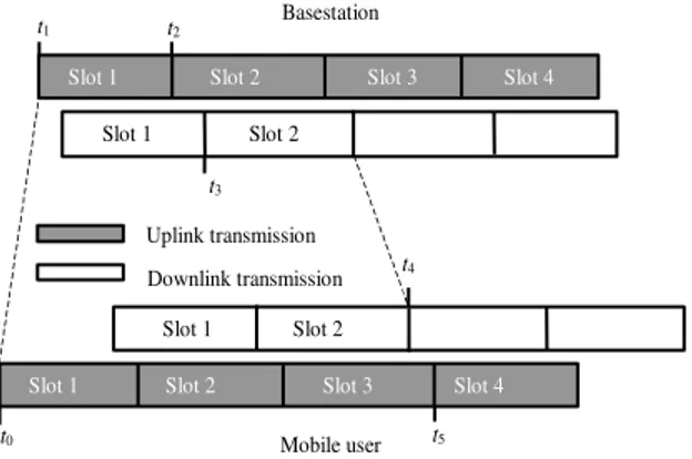
3Tp is usually assumed to model a real system. Figure 2 illustrates the condition
of a real system from which the feedback delay can be determined.
t0
t1 t2
t5
Slot 1 Slot 2 Slot 3 Slot 4
Slot 1 Slot 2 Slot 3 Slot 4
t3
t4 Slot 1 Slot 2
Slot 1 Slot 2
Basestation
Mobile user Uplink transmission
Downlink transmission
Figure 2 Illustration of feedback delay on uplink power control algorithm
Consider that a mobile begins transmitting data in the time slot 1 at time t0. This
time slot (slot 1) will arrive at the base station at time t1, which takes (t1– t0) for
completed at time t2. In this case, SIR measurement is performed over one time
slot duration. At this time, the base station compares the estimated SIR with the target SIR to produce the command bit.
As we can see from Figure 2, the command bit should wait until time t3 when
the downlink begins transmission the slot 2. After propagating in the downlink, the command bit is received by the mobile user at time t4, in which slot 2 of the
downlink has been received by the mobile station. This mobile station then adjusts its power at time t5 (the beginning of slot 4 transmission in the uplink).
This situation leads to a total feedback delay D = 3Tp.
2.3
Channel Prediction
In a D-step linear prediction of order V, the predicted fading-factor is expressed as a linear combination of the previous samples {(i – D), (i – D –1), …, (i – D – V+1)} as
) (
) ( )
(
1
0
v D i i a
i v
V
v
pred
(4)
where av(i), v = 0, 1, …, V-1 are the linear prediction coefficients for the i th
slot, (i) is the channel gain or the received signal strength which represents the fading factor, and D is the prediction range to reflect up to how many step ahead the prediction is conducted. By using the orthogonal principle, the vector a(i) =[a0(i) a1(i) … aV-1(i)]
T
under the minimum mean square error (MMSE) criterion can be computed as follow
a(i) = R-1(i)r(i). (5)
Here R(i) is the V x V autocorrelation matrix of the input samples, whose elements are r(i)v,u = E[(i – D – v)
*
(i – D – u)], v, u = 0, 1, …, V-1. The vector r(i) is the cross-correlation between the tap-input samples and the desired response. Elements of vector r(i) are r(i)v = E[(i) *(i – D – v)], v = 0, 1, …,
V-1. E[.] is the expectation operator.
In practice, however, the analytical solution to compute the predictor coefficients a(i) is not recommended because it is computationally intensive due to the complexity of R matrix inversion and also numerically sensitive due to the fact that the matrix R can be ill-conditioned. In addition, the maximum Doppler spread fD can be time varying during a call duration that is not easy to
3
Improved Channel Prediction
In this section an improved power control scheme using a predictive algorithm is described. Predictive algorithm aims at predicting the future sample values using the correlation property of the past sample values. In the predictive power control algorithm, however, the correlation of past sample values is destroyed by power control updating factors.
In this study, the number of CDMA users is assumed to be large and therefore using the central limit theorem the multiple access interference is Gaussian distributed. As a result the SIR measured at the base station corresponds with the received signal strength which reflects the channel gain. However, since the received signal level or SIR has been updated by power control updating, in this paper the past power-controlled fading factor or the past SIR values, (i – D – v), v = 0, 1, …, V – 1 need to be compensated for by the same factors that were given by power control updating. The restored SIR values as input samples to the predictor can be expressed as
) (
10 )
(
' [ ( )]/10
1
v D i v
D
i e i Du
v
u
q
(6)
where γ (i – D – v) is the power-controlled SIR, γ’(i – D – v) is the restored SIR that can be used as the input samples to the channel predictor, and eq(i-D-u) is
the control parameter to increase or decrease the transmit power reflecting the power increment step-size at the mobile station in decibel. The product term in the right-hand side of (6) indicates the total power-control gain accumulated during the v power-control interval. Therefore, the prediction algorithm can utilize the correlation property of the fading channel despite the power control updating factors.
4
Simulation and Results
In the simulation, a single-cell CDMA system with the number of users K is varried to see its effect on BER performance is considered. To reflect a practical
situation, all users are considered in motion with different vehicle’s speeds and
thus have different maximum Doppler spreads. We model this situation by
varying the users’ vehicle speeds from 10 to 10 k km/h at 10 km/h interval (i.e.,
the speed of the kth user is vk = 10 k km/h for k = 1, 2 , …, K). Carrier frequency
fc = 1.8 GHz is used, so that the corresponding maximum Doppler spreads, fD
for the users are approximately ranging from 17 to 17 K Hz at 17 Hz interval. The DS-CDMA processing gain is M = 64 and the modulation scheme is QPSK with a data rate Rb = 120 kbps (symbol rate Rs = 60 ksps in QPSK scheme). The
control interval Tp = 0.667 ms. SIR measurement is performed during a period
of one time slot that corresponds to one power control interval Tp = 0.667 ms.
The chip rate Rc = 3.84 Mcps as given in the 3G specification for uplink data
channel [9] is assumed in the simulation, resulting in each time slot to contain 2560 chips. Therefore, 40 binary symbols per time slot are available for SIR measurement. The simulation parameters are summarized in Table 1.
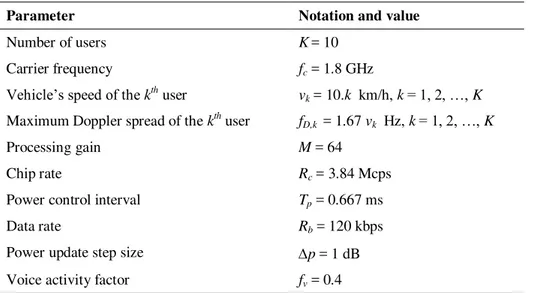
Table 1 Simulation parameters of CDMA BER performance.
Parameter Notation and value
Number of users K= 10
Carrier frequency fc = 1.8 GHz
Vehicle’s speed of the kthuser vk = 10.k km/h, k= 1, 2, …, K
Maximum Doppler spread of the kthuser fD,k = 1.67 vk Hz, k= 1, 2, …, K
Processing gain M = 64
Chip rate Rc = 3.84 Mcps
Power control interval Tp = 0.667 ms
Data rate Rb = 120 kbps
Power update step size p = 1 dB Voice activity factor fv = 0.4
The simulation is conducted for fDTp = 0.01, and the performance is evaluated in
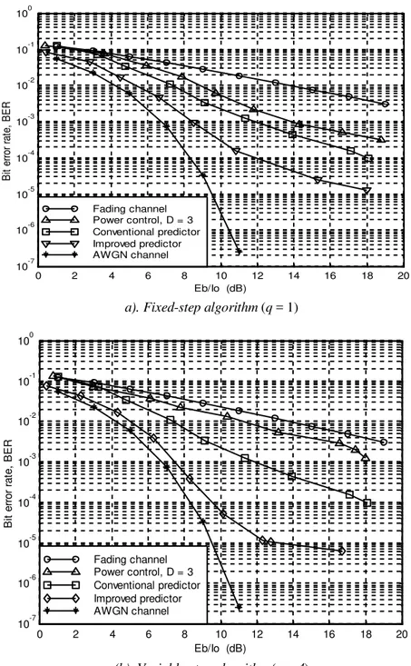
terms of bit error rate (BER) as a function of bit energy-to-interference power density ratio (Eb/I0). Simulation was conducted to evaluate the performance in
terms of bit error rate (BER) performance as a function of Eb/No as shown in
Figure 3 (a)for fixed step algorithm and (b) for variable step algorithm with quantization level q=4.
0 2 4 6 8 10 12 14 16 18 20 10-7
10-6 10-5 10-4 10-3 10-2 10-1 100
B
it
er
ro
r
ra
te
,
B
E
R
Eb/Io (dB) Fading channel
Power control, D = 3 Conventional predictor Improved predictor AWGN channel
a). Fixed-step algorithm (q = 1)
0 2 4 6 8 10 12 14 16 18 20 10-7
10-6 10-5 10-4 10-3 10-2 10-1 100
B
it
e
rr
o
r
ra
te
,
B
E
R
Eb/Io (dB) Fading channel
Power control, D = 3 Conventional predictor Improved predictor AWGN channel
(b). Variable-step algorithm (q = 4)
From Figure 3 (a) and (b), we can also see that for feedback delay D = 3Tp the
fixed step algorithm has a better performance than the variable-step algorithm. This can be explained that feedback delay causes the power adjustments become obsolete and irrelevant to the actual channel condition, and therefore resulting in large deviations of the SIR from the target SIR level. Since the incremental power step size in variable-step algorithm can be variable, the deviation or power control error can also be larger than that of the fixed-step algorithm. Thus, the performance of variable step algorithm degrades more significantly with feedback delay. However when the channel predictor is used, the variable-step algorithm significantly outperforms the fixed-step algorithm. When channel predictor is used, however, the transmit power adjustments take place at the actual channel measurement time, and therefore become relevant with the current channel condition. Since the variable-step algorithm uses multiple PCC bits to convey various adjustment levels, it can better track the channel variation than that of the fixed step algorithm. Therefore, variable step algorithm outperforms the fixed step algorithm significantly when channel predictor is used. We can see that to achieve BER = 10-3 the improved predictive algorithm has almost 4 dB gain and for variable step algorithm has almost 5 dB gain compared to that for conventional predictive algorithm. This result has been previously shown on [10]. In this paper, further evaluation of predictive power control algorithm is performed to see its effect on the CDMA capacity. To evaluate the effect of the proposed method on CDMA system capacity, simulation was conducted in terms of bit error rate as a function of the number of user. The simulation parameters are shown in Table 2.
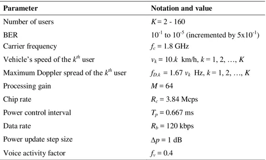
Table 2 Simulation parameters of CDMA capacity performance.
Parameter Notation and value
Number of users K= 2 - 160 BER
Carrier frequency
10-1 to 10-5 (incremented by 5x10⁻¹)
fc = 1.8 GHz
Vehicle’s speed of the kthuser vk = 10.k km/h, k= 1, 2, …, K
Maximum Doppler spread of the kthuser fD,k = 1.67 vk Hz, k= 1, 2, …, K
Processing gain M = 64
Chip rate Rc = 3.84 Mcps
Power control interval Tp = 0.667 ms
Data rate Rb = 120 kbps
To evaluate the capacity performance, the simulation parameters of the CDMA BER performance shown in Table 1 are kept the same, but this time we increment the number of user from 1 to 160 users and we monitor the resulting number of users associated with any particular value of BER. In fact, when we increase the number of user in our simulation model, we can detect the resulting values of BER.
The results for fixed step algorithm (q=1) and for variable step algorithm (with quantization level q = 4) are shown in Figure 4 (a) and (b), respectively. We can see from Figure 4 (a) and (b) that for both the fixed-step and variable-step algorithms, the CDMA system capacity increases significantly when the improved prediction method is employed. From Figure 4 (a) and (b), we can also see that for feedback delay D = 3Tp the fixed step algorithm produces a
higher capacity than the variable-step algorithm. However when the channel predictor is used, the variable-step algorithm significantly outperforms the fixed-step algorithm.
Numerical results from Figure 4 show that the proposed improved power control algorithm exhibit more than 40 % increase for fixed step algorithm and more than 50 % increase in capacity for variable step algorithm from that of the conventional prediction algorithm. For variable step power control scheme with q=4 the proposed algorithm can provide a near-ideal-channel capacity (less than 15 % below AWGN channel capacity).
(b) Variable step algorithm (q=4)
Figure 4 CDMA capacity for various power control algorithms
5
Conclusion
q=4 the proposed algorithm can provide a near-ideal-channel capacity (less than 15 % below the capacity of AWGN channel).
References
[1] Gilhousen, K.S., et al., On the Capacity of a Cellular CDMA System, IEEE Transaction on Vehicular Technology, 40, pp. 303-312, May 1991. [2] Kurniawan, A., Effect of feedback delay on fixed step and variable step
power control algorithms in CDMA systems, in Proceedings of the 8th International Conference on Communication Systems (ICCS) 2002, Singapore, CD-ROM 3P-02-04, November 2002.
[3] Lau, F.C.M. & Tam, W.M., Novel SIR-estimation-based power control in a CDMA mobile radio system under multipath environment, IEEE Transactions on Vehicular Technology, 50(1), pp. 314-320, January 2001.
[4] Gilhousen, K.S., Jacobs, I.M., Padovani, R. & Weaver, L.A., Jr., Increase capacity using CDMA for mobile satellite communications, IEEE Journal on Selected Areas in Communications, 8(4), pp. 503-513, May 1990. [5] Chockalingam, A., Dietrich, P., Milstein, L.B. & Rao, R.R., Performance
of closed-loop power control in DS-CDMA cellular systems, IEEE Transactions on Vehicular Technology, 47(3), pp. 774-778, August 1998. [6] Chung, C.J., Lee, J.H. & Ren, F.C., Design of power control mechanisms
with PCM realization for the uplink of a DS-CDMA cellular mobile radio system, IEEE Transactions on Vehicular Technology, 45(3), pp. 522-530, August 1996.
[7] Ariyavisitakul, S., SIR-based power control in a CDMA system, in Proceedings of IEEE Global Telecommunications Conference, Orlando, USA, pp. 868-873, December 1992.
[8] Kurniawan, A., Predictive Power Control in CDMA Systems. PhD dissertation, Institute for Telecommunications Research, University of South Australia, 2002.
[9] 3GPP Consortium, Physical channels and mapping of transport channels onto physical channels (FDD), Third Generation Partnership Project (3GPP) Technical Specification TS 25.211, v2.5.0, October 1999.