Loosed Coupled Simulation of Smart Grid Control Systems
Adriano Ferreira
˚;, Paulo Leit˜ao
˚:, Jos´e Barata
;˚Polytechnic Institute of Braganc¸a, Campus Sta Apol´onia, 5300-253 Braganc¸a, Portugal
{a.ferreira, pleitao}@ipb.pt
:Artificial Intelligence and Computer Science Laboratory, 4169-007, Porto, Portugal
;New University of Lisbon, Faculty of Sciences and Technology, Quinta da Torre,
2825-114 Caparica, Portugal, jab@uninova.pt
Abstract—Smart grids rely on the integration of distributed energy resources towards an intelligent and distributed manner to organize the electrical power grid enabled by a bidirectional flow of information to improve reliability and robustness, fault detection and system operation, and plug-and-playability of en-ergy devices. The integration of information and communication technologies (ICT), one of the key enablers of smart grids, will ease the deployment of intelligent and distributed systems implementing the automation functions. In this context, there is a need to assess how these systems, developed using these emer-gent technologies, e.g., multi-aemer-gent systems, data analytics and machine learning, will behave and affect the working conditions of the power grid. This paper aims to explore the development of a transparent and loose-coupled interface between the behavioral control system and the physical or simulated power system environment, in a coupled simulation perspective, aiming to assess and improve the development of such systems during the design phase.
Index Terms—Simulation, Smart grids, Multi-agent Systems, Matlab Simulink.
I. INTRODUCTION
Global warming awareness allied to the agreements achieved in the Kyoto protocol has enforced new restraints in the electric generation. Green and eco-friendly energy sources are now becoming prominent for a sustainable and carbon free development, which allied with the technological break-throughs in ICT, poses the ideal conditions for the transition of the traditional power grid towards a smart grid [1].
The smart grid not only aims to address ecological issues, but also to reduce the centralized energy generation by sup-porting the integration of distributed energy resources (DER), grid monitoring and control through demand response (DR) and advanced metering infrastructure/reading (AMI/AMR) technologies. This evolution towards a smarter grid and the in-tegration of new technologies promises to bring enhancements in several fields, namely power quality and reliability, reduced generation costs, improved asset management and economic benefits to customers [2].
This evolution comes allied with the emerging technologies associated to Internet of Things (IoT), which is not only present in the smart grid and energy management field [3] but also everywhere, namely environmental monitoring [4] and smart factories [5]. It provides decoupling and decentralization capabilities to the devices placed in the ecosystem, potentiating the distributed management and control of physically dispersed devices and technologies.
The resulting evolution originates an aggregation of sev-eral types of technologies, ranging from power electronics to communication infrastructures, leading to a complex and multi-disciplinary cyber-physical system that integrates several heterogeneous and distributed energy resources, as well as, computational applications for control and monitoring of the power grid operation. Multi-agent systems (MAS) is pointed as a suitable approach to introduce distributed intelligence in power grid control and operation. In fact, MAS provides autonomous control actions in a distributed and decentralized manner matching the distributed nature of the smart grid and its devices [6].
The assessment and verification of such distributed smart grid systems becomes a primordial part of the development that has to be performed prior to the system deployment. This issue poses a barrier when it comes to simulate such systems, as in the past the different domains of the smart grid have been modeled separately, having simulators where control strategies (e.g., market operation and demand side management techniques) were simulated, and power grid sim-ulators where the physical behavior is tested (e.g., frequency stability and power factor correction). In this last physical component, there are available power grid simulators, e.g., Matlab Simulink [7] and Gridlab-D [8], that can be used to provide a realistic environment to simulate the control and monitoring applications for smart grids.
Having this in mind, a simple, loose-coupled and transparent interface platform is required to interconnect the behavioral part of the grid, i.e. where the control and monitoring proce-dures take place, e.g., by using MAS solutions, and the phys-ical part of the grid, i.e. where different power systems can be modeled in detail using a realistic simulation environment. Therefore, this interface should allow to merge different tools and techniques to simulate the different parts of the overall complex system simultaneously.
This paper presents a loose-coupled simulation interface that simplifies the interaction between the behavioral simulation counterpart of smart grid systems with the physical power grid simulation. The validation of the proposed approach was performed by interfacing a MAS solution for the high level control developed by using the JADE framework with a micro grid case study modeled in Simulink.
interface for combining behavioral and physical simulation counterparts. Section IV describes the experimental tests and analyses the results from the implementation of the proposed approach to interface a JADE based MAS solution with a micro grid modeled with Simulink. At last, Section V rounds up the paper with conclusions and points out the future work.
II. RELATEDWORK
A. Simulation of Smart Grids
Simulation provides the possibility to create different mod-els where different realities can be combined. As example, by combining the simulation of a control system with power grid simulators that are operating in parallel with the real power grid, such simulation can bring one step closer to the implementation of the designed control models.
Simulation approaches, that typically involve the integration of two or more simulators to assess the cyber-physical inter-dependency of a process or system, poses that each modeled system is analyzed in its dedicated simulation environment [9]. Some research deals with the distribution of simulation across several computers and devices enabling the possibility to break down a system into subsystems, which can be mod-eled independently. Therefore, distributed simulation enables to [10]:
‚ Parallelize computing, improving the overall performance
of the simulation processing.
‚ Combine heterogeneous simulators that may focus on
different simulation objectives.
‚ Combine hardware and software, join the hardware to the
simulation process (hardware-in-the-loop).
The heterogeneity of the smart grid, as well as the need to simulate simultaneously the control and physical layers, requires the creation of a mean to interconnect these two worlds. Several works can be found in the literature review.
Kelley et al. presented the federated simulation toolkit (FSKIT)that couples continuous time and discrete event sim-ulations (DES), joining the power system and communication network simulations into an integrated tool [11]. A modular simulation framework called Mosaik is presented in [12], supporting automatic composition of heterogeneous simulation models in order to evaluate control strategies.
In [13], the authors developed a simulation engine called EPOCHS which combines PSCADE/EMTDC, PSLF and NS2 together with multi-agent systems. A run-time infrastructure (RTI) was used to route all the messages between the simula-tion components as well as manage simulasimula-tion times while the distributed control and protection schemes were implemented using agents. Roche et all in [14] developed an interface that joins the PowerWorld (power system simulator) and JADE (agent environment) using TCP/IP and MATLAB as a simulation controller.
The authors in [15] proposed a simulation framework called GridIQ that interfaces JADE with PSAT (Power Simulation Analysis Tool). The framework acts as an interface between the two distinct simulators, although the authors considered the
communication times between the agents to be ideal, which makes it unrealistic. The MACSim software framework [16] simulates a MAS application and the communication network, being the JADE framework used to develop the MAS environ-ment and OPNET as network simulator, although the power grid simulation was no considered. A similar approach was presented in [17] that provides a modeling and development of multi-agent driven control systems.
Roche et. al [14], presented a framework that interfaces power systems analysis software, such as Matlab and Power-World, with multi-agent system developed by using the JADE framework. The main aim of this framework is to enable reliable communication and coordinated interaction between the two types of tools. The two tools interact via a TCP/IP (transmission control protocol)/(Internet Protocol) where the agents act as coordinator via the InterfaceAgent and Matlab as a slave.
B. Synchronization Structure
The synchronization of connected simulation tools from different domains is crucial to achieve a coherent simulation. Fig. 1 illustrates the synchronization scheme proposed by [18] describing the simulation between the behavioral simulation and the power grid simulation. The two simulation engines are coupled between a synchronization scheme that explicitly synchronizes the shared variables and simulation time.
Fig. 1. Synchronization Structure adapted from [18]
Each simulator locally stores the current state and time at which the state is valid. Thus, letτBSbe the current state of the behavioral simulator (BS) at simulation timetBS, and letτP S be the internal state of the power simulator (PS) at simulation timetP S. The defined controllable variables are set by the BS (defined inσc and read by the PS; the simulated variablesσm are set by the power simulator and read by the BS. Consider a synchronized cycle, a cycle which starts with the two simulator having a common simulation time (tBS=tP S). On each cycle, the BS set the values and defines a watching simulation time δt by which the simulation should be performed by the PS. The result variables σ1
BS simulation remains unaltered, simulation time remains at tP Sand stateτBS. The simulation will then advance byδtq so that both BS and PS are once again synchronized at the same simulation time and the simulated variables are updated σ1 c and the new time step is proposed to the PS. The granularity of the time step is always determined by the BS.
C. Existing Gaps and Requirements
Combining different simulation environments in a dis-tributed and loose-coupled manner poses several issues.
The literature review reveals the existence of some ap-proaches that create a combined simulation environment that brings the control and physical simulations together. However, they lack a toughly decoupled, standard and transparent com-munication environment that enables to integrate distributed and loose-coupled simulation platforms and devices.
Taking a closer look of the above review of the state of the art is perceptible that works presented use either a hard coded communication channel that need to be reworked if a new/different simulator is added or the interfaced tools work in the same machine with no need for a communication channel. Therefore there is a need to create a loose-coupled com-munication channel that can provide the inter-exchange of simulators and physical devices in order to interconnect them as a whole simulation environment. This loose-couple interface framework for simulation environment should consider the following requirements:
1) Synchronization of the data exchange: the timing issue is very important as it ensures a proper information exchange between simulators.
2) Coordination and execution scheduling of all simula-tions: the proper scheduling and coordination of the simulations ensures that they are started at the correct time. This ensures a proper simulation synchronization avoiding simulation delays.
3) Track simulation time: ensure that all simulations have access to current simulation time.
4) Simplify the data exchange facilitation: exchange data between the different simulations using a common com-munication bus.
5) Loose-Coupling: ensures that the simulations are dis-tributed requiring less computational resources.
III. DESIGN OF THELOOSEDCOUPLEDINTERFACE
The evolution of the systems poses that plug-and-play capabilities should be found in simulation environments where the evolution and complexity grow, requires them to be loose coupled and easily scalable.
A. Philosophy and Application Domain
Components in a loosely coupled system can be changed or replaced with alternative implementations that provide the same or similar services, being less constrained to the same platform, language, operating system, or build environment. The maintenance of the system consistency in loose coupled systems requires a special attention.
Loosed coupling provides a way to spread the simulation across multiple devices replicating, in many cases, the layout of the simulated scenario. This replication is not only in terms of communication conditions but also in terms of decentralization of the simulation by distributed computa-tional resources. The principal deployment scenario of loosely coupled simulation is to interlinking heterogeneous system simulators to achieve an integrated simulation tool chain, with the possibility of swapping software components. In this scenario, the physical power grid and behavioral simulator counterparts exchange real-time data allowing the complete verification of the developed models.
Therefore, using such techniques testing and simulation of control strategies on electrical power systems, are approached to real case scenarios replicating possible instabilities in the electrical system. Therefore, it provides a safe environment to benchmark the quality of the control algorithms as well as perform the behavioral and decision-making tests.
B. Simulation Communication Channel
The different simulators need to interact in order to commu-nicate and perform the joint simulation process. For this pur-pose, the interconnection between the two layers is supported by a MQTT (Message Queuing Telemetry Transport) broker providing a lightweight method of carrying out messaging using a publish/subscribe model. The MQTT protocol has its roots back in 1999, invented by IBM and Arcom for oil field and food plain monitoring [19]. MQTT is designed to provide efficient communication across a wide area portion of the net-work. Unlike HTTP (Hypertext Transfer Protocol) applications that would have to continuously poll to query a given status inefficiently using the network, and CPU resources. MQTT enables applications to listen for events and goes to idle until the event occurs at which point the event will be pushed to the listening application
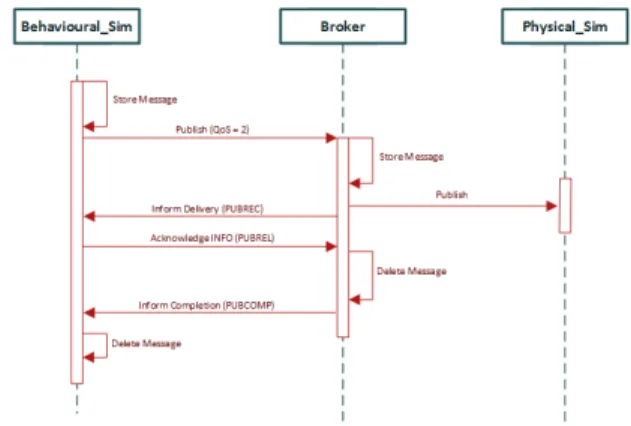
The MQTT protocol also allows customizable levels of QoS. Therefore, each publish event will use QoS level 2 in order to ensure a reliable and unique delivery by each publisher [20]. Each message will be stored by the sender until the delivery acknowledgment sent by the broker is received, this process is described in Fig. 2.
As example, an PV agent will start by locally store the mes-sage to be sent, then it will publish (e.g.radiation values to be used in the physical simulator model) to the broker. The broker will store the message locally and then forward the message to the subscribers of that topic trough a publish event. The broker will then acknowledge the publisher that the message has been successfully delivered. After a successful delivery the publisher and the broker will exchange acknowledgment messages in order to delete the stored message.
Fig. 3. Simulation interface between behavioral and power simulators
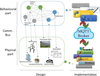
The main responsibility of the broker is to ensure proper communication between the clients and ensure the message distribution between them. When a message is received the broker as find all the clients that have a subscription to the received topic and forward the message. Besides the message handling, the broker checks authentication and authorization of the clients. The client will send a connect message that will contain a username and password that will be checked by the broker, additionally, on the broker side topic permission is implemented as a mean to block unauthorized clients to public or subscribe. Fig. 3 describes how the different interfaces composed by a behavioral simulators, comprising the high-level decision-making and coordination functionalities imple-mented, and the functional simulators that emulates the power grid using a power grid simulator can interact using a common communication channel such as a broker.
C. Simulation Data Structure
The data shared trough the Mosquito broker, between the simulators uses a JSON structure where each message has the following content:
‚ Message id: identifies the sender and number of the
message.
‚ Type: identifies the type of the message content, e.g.,
Boolean, double and character.
‚ Parameter: identifies the exchange parameter, e.g.,
rad P V H12 is the radiation parameter for the con-nected PV in house 12.
‚ Value: contains the value for the content parameter
pre-viously described.
This structure eases the process of bug tracking as each received message is stored locally in the receiver’s local data base for a predetermined amount of simulation cycles until is deleted to give place to new incoming messages.
The following piece of code describes the structure of a message exchange between the two ends of the simulation infrastructure.
example {
"MessageID": "Sender_Msgnumber", "Type": "Float",
"Parameter": "rad_PV_H12", "Value": "12"
}
D. Simulators Schedule
As the different entities present in the simulation model have dependencies between each other, e.g., the simulation of a PV requires input from the weather simulation or the load scheduling requires input from the prediction models. Additionally, the simulator can be started by other simulators and have different time steps.
In order to solve the dependencies and avoid the desynchro-nization, the simulations that are inputs for other simulation processes are started whenever they are needed. Fig. 4 shows the graph sequence for the above example, assuming thatSim2
andSim3 provide inputs for Sim1, and Sim1 provides inputs for Sim4.
Fig. 4. Simulations schedule graph
Considering the discrete event simulator in the simulation as theSim1and the continuous simulator as theSim4, the dis-crete simulator will locally launch all the necessary auxiliary simulations and wait for the input or use the previous state in case of non response. The result will be communicated to a continuous simulator that will wait for all other necessary events and data before proceeding with the simulation. This means that for this case the discrete simulator handles the necessary simulation triggers, acting as a master (Sim1) and the continuous simulator as a slave (Sim4).
..., Setpnu, n P Nthe fixed simulation steps. The maximum
simulation step time will be equal to biggest simulation duration. Therefore, the global synchronization point for the simulation period presented in the above example (Fig. 4) is the point where all the simulators have shared the results. Therefore, the global synchronization is the point of the return value of the continuous simulator (Sim4).
IV. EXPERIMENTAL IMPLEMENTATION
The following subsections describe the case study and the implementation of the proposed approach to simulate a small microgrid.
A. Description of the Case Study
The case study considered in this work is a small low-voltage microgrid with four households, each one comprising 7 different loads as follows:
‚ Water heater (2kW).
‚ Electric heater (2kW).
‚ Illumination (200W).
‚ Refrigerator (200W).
‚ Television (200W).
‚ Microwave (800W).
‚ Emergency illumination (100W).
Several renewable energy supplies, as well as storage de-vices, are available to supply energy to these loads, as follows:
‚ 1 residential house with no generation or storage.
‚ 1 Residential house with 1 PV 5Kwp, 1 electric vehicle
50Ah and no storage.
‚ 1 Residential house with no generation and 1 battery bank
80Ah for storage.
‚ 1 Residential house with 1 wind generator 2.4Kwp and
no storage.
‚ shared generation and storage with 1 PV 5Kwp, 1 wind
generator 2.4Kwp and 1 battery bank 100Ah.
The shared generation and battery banks are part of the community, meaning that all residential houses can get energy from these energy units. The primordial use for the generation units is to be applied within the residential units and the surplus stored within the batteries and EV.
The microgrid was modeled in both behavioral and power grid simulators. The behavioral system responsible the power grid operational control modeled and implemented using the MAS technology through the JADE framework. The physical grid simulator implement using Simulink, where each power grid element is designed and represented through its equivalent block diagram.
B. Implementation
In the behavioral simulation, each agent has its physical representation in the power grid model developed using the Simulink simulator and is isolated in its own machine con-stituting a fully decoupled environment. Each agent is both subscriber and publisher of topics where all are related and individual topics that deal with the physical grid simulation,
e.g. a PV agent accessing data from the simulated generation or change the data of the sun radiation.
In the physical layer modeled within the Simulink en-vironment, each power grid element is designed to be as close as possible to the real equipment in terms of electric characteristics. Alt ought, power grid is simulated as a whole, having each modeled power grid element inputs and outputs connected to subscribed topics in MQTT broker. This is achieved through an open source library called Paho that is an open source MQTT client implementation for java that enables to create a client connection to an MQTT broker running on a host, over TCP to port 1883 (the default port for MQTT). Paho is present in each agent implementation creating a MQTT client for each instance, on the Simulink side one client is present through the Matlab Java API.
The synchronization and simulation processes between both simulations are started by he agents that always act as master whereas the Simulink act as a slave answering to queries performed by the agents.
C. Results Discussion
The developed system interface was tested to assess the characteristics of the simulation interface.
1) Latency Times: The assessment of the device-to-device Publish-Subscribe latency, respecting the QoS 2, between the agents and the Simulink environment, an experimental test was performed considering two scenarios:
‚ Case 1: small dummy simulation on Simulink side and
dummy communication content.
‚ Case 2: full use case simulation on both sides.
The latency times were calculated by measuring the time between the publish event and the acknowledgment of de-livery by the broker, performing from both sides during the simulation runtime and after the end simulation by Simulink. Table I summarizes the latency times During (top of the table) the simulation runtime andAfter(bottom of the table) a finished simulation by Simulink with data request from both sides.
TABLE I
LATENCYTIMESDURING ANDAFTER THESIMULATIONRUNTIME
Request by MAS Request by Simulink Time (ms) Case1 Case2 Case1 Case2
During 232 341 246 286
Af ter 158 180 168 171
The observation of the results allows to verify that the com-putational requirements of the Simulink environment affect the communication latencyDuringthe simulation. The latency increases to 341 ms in Case2 when compared to 232 ms in
Case1during the simulation runtime requested by MAS. The same behavior can be observed when the Simulink performs the request.
communication latencies, although with less significant in-creases 22 ms for the MAS request and 3 ms for the Simulink. The simulation execution times would be reduced, and the wole systems performance would benefit from a distributed simulation from the Simulink side.
2) Scalability: Due to the necessity to map each electrical entity in both layers, the proposed approach turns-it labor in-tensive in order to scale-it up. Although, power grids tend to be quite static with few changes over the years. This would mean that few modifications within the structure of the Simulink model, as well as in the agent-based system side, would mean to clone an agent and correct the dependencies. Although, the implementation of the Simulink simServer would solve the need to completely redesign the whole micro grid structure and transform it in a modular addition where each entity will be a co-model of the overall simulation.
3) Possible Change of Simulators: The changes of the sim-ulator environment, at both simulation layers, is possible with-out changes within the broker structure and subscribed/pub-lished topics. Additionally, the change in the physical simu-lation counterpart does not affect the behavioral counterpart since it is decoupled through the use of the broker interface. Although, in case of a coding language change, the MQTT client topic subscriptions would necessarily to be recoded.
V. CONCLUSION
Simulation should mimic the design and behavior character-istics of the simulated system, needing in this case separated and distributed models for both behavioral and physical sim-ulations, as well as a communication channel that interfaces them.
The publish/subscribe schema is a distributed interaction paradigm well adapted to support the deployment of scalable and loosely-coupled systems. This paper presented a trans-parent and loose coupled interface to interconnect an agent-based control system and the corresponding electrical power system modeled in a proper simulator environment, in a smart grid context, using a publish/subscribe framework. The generic interface between both layers is described, and posteriorly implemented using the JADE framework and the Simulink environment, and tested to assess the communication bound-aries of the proposed implementation. The experimental results allowed to verify that by loosely-coupling different types of simulation platforms it is possible to simulate and evaluate the microgrid from behavioral and physical perspectives.
Future work will be devoted to apply the proposed ap-proach towards the development and testing of intelligent and distributed multi-agent based solutions that manage the self-sustainability of micro grids.
REFERENCES
1 L. Dusonchet and E. Telaretti, “Economic analysis of different supporting policies for the production of electrical energy by solar photovoltaics in western European Union countries,”Energy Policy, vol. 38, no. 7, pp. 3297–3308, 2010.
2 S. Karnouskos, O. Terzidis, and P. Karnouskos, “An Advanced Metering Infrastructure for Future Energy Networks,”New Technologies Mobility and Security, pp. 597–606, 2007.
3 M. Moness and A. M. Moustafa, “A Survey of Cyber-Physical Advances and Challenges of Wind Energy Conversion Systems: Prospects for Internet of Energy,” IEEE Internet of Things Journal, vol. 3, no. 2, pp. 134–145, 2016.
4 M. T. Lazarescu, “Design of a WSN platform for long-term environmental monitoring for IoT applications,”IEEE Journal on Emerging and Selected Topics in Circuits and Systems, vol. 3, no. 1, pp. 45–54, 2013. 5 F. Shrouf, J. Ordieres, and G. Miragliotta, “Smart factories in Industry
4.0: A review of the concept and of energy management approached in production based on the Internet of Things paradigm,” in IEEE International Conference on Industrial Engineering and Engineering Management, vol. 2015-January, pp. 697–701, 2014.
6 N. Hatziargyriou, H. Asano, R. Iravani, and C. Marnay, “Microgrids,”
IEEE Power and Energy Magazine, vol. 5, pp. 78–94, jul 2007. 7 M. E. Ropp and S. Gonzalez, “Development of a MATLAB/simulink
model of a single-phase grid-connected photovoltaic system,”IEEE Trans-actions on Energy Conversion, vol. 24, no. 1, pp. 195–202, 2009. 8 D. P. Chassin, K. Schneider, and C. Gerkensmeyer, “GridLAB-D: An
open-source power systems modeling and simulation environment,” in
2008 IEEE/PES Transmission and Distribution Conference and Exposi-tion, pp. 1–5, IEEE, apr 2008.
9 M. Garau, G. Celli, E. Ghiani, F. Pilo, and S. Corti, “Evaluation of smart grid communication technologies with a co-simulation platform,” IEEE Wireless Communications, vol. 24, pp. 42–49, April 2017.
10 A. M. Kosek, O. L¨unsdorf, S. Scherfke, O. Gehrke, and S. Rohjans, “Evaluation of smart grid control strategies in co-simulation-integration of IPSYS and mosaik,”Power Systems Computation Conference, pp. 1–7, aug 2014.
11 B. M. Kelley, P. Top, S. G. Smith, C. S. Woodward, and L. Min, “A federated simulation toolkit for electric power grid and communication network co-simulation,” in2015 Workshop on Modeling and Simulation of Cyber-Physical Energy Systems (MSCPES), pp. 1–6, April 2015. 12 S. Sch¨utte, S. Scherfke, and M. Tr¨oschel, “Mosaik: A framework for
modular simulation of active components in Smart Grids,” in IEEE 1st International Workshop on Smart Grid Modeling and Simulation, (SGMS), pp. 55–60, 2011.
13 K. Hopkinson, X. Wang, R. Giovanini, J. Thorp, K. Birman, and D. Coury, “Epochs: a platform for agent-based electric power and communication simulation built from commercial off-the-shelf components,”IEEE Trans-actions on Power Systems, vol. 21, pp. 548–558, May 2006.
14 R. Roche, S. Natarajan, A. Bhattacharyya, and S. Suryanarayanan, “A framework for co-simulation of AI tools with power systems analysis software,” in Proceedings - International Workshop on Database and Expert Systems Applications, DEXA, pp. 350–354, IEEE, sep 2012. 15 C. J. Bankier, “Gridiq - a test bed for smart grid agents,” 2010. 16 F. Perkonigg, D. Brujic, and M. Ristic, “Mac-sim: A multi-agent and
com-munication network simulation platform for smart grid applications based on established technologies,” in2013 IEEE International Conference on Smart Grid Communications (SmartGridComm), pp. 570–575, Oct 2013. 17 C. R. Robinson, P. Mendham, and T. Clarke, “MACSimJX: A tool for enabling agent modelling with simulink using JADE,”Journal of Physical Agents, vol. 4, no. 3, pp. 1–7, 2010.
18 J. Fitzgerald, P. G. Larsen, and M. Verhoef, eds.,Collaborative Design for Embedded Systems. Springer Berlin Heidelberg, 2014.
19 R. Lewis,Advanced Messaging Applications with MSMQ and MQSeries. Que, 1999.
![Fig. 1 illustrates the synchronization scheme proposed by [18]](https://thumb-eu.123doks.com/thumbv2/123dok_br/16865424.753947/2.918.497.828.572.800/fig-illustrates-synchronization-scheme-proposed.webp)