DETECTING AND ANALYZING CORROSION SPOTS ON THE HULL OF LARGE
MARINE VESSELS USING COLORED 3D LIDAR POINT CLOUDS
A. K. Aijazia,b,∗, L. Malaterrea,b, M. L. Tazira,b, L. Trassoudainea,b,∗and P. Checchina,b,∗
a
INSTITUTPASCAL, Universit´e Blaise Pascal, Clermont Universit´e, BP 10448, F-63000 Clermont-Ferrand, France bI
NSTITUTPASCAL, CNRS, UMR 6602, F-63171 Aubi`ere, France
kamalaijazi@gmail.com; laurent.trassoudaine@univ-bpclermont.fr; paul.checchin@univ-bpclermont.fr
KEY WORDS:3D LiDAR point clouds, Detection of defects, Ships
ABSTRACT:
This work presents a new method that automatically detects and analyzes surface defects such as corrosion spots of different shapes and sizes, on large ship hulls. In the proposed method several scans from different positions and viewing angles around the ship are registered together to form a complete 3D point cloud. TheR,G,B values associated with each scan, obtained with the help of an integrated camera are converted intoHSVspace to separate out the illumination invariant color component from the intensity. Using this color component, different surface defects such as corrosion spots of different shapes and sizes are automatically detected, within a selected zone, using two different methods depending upon the level of corrosion/defects. The first method relies on a histogram based distribution whereas the second on adaptive thresholds. The detected corrosion spots are then analyzed and quantified to help better plan and estimate the cost of repair and maintenance. Results are evaluated on real data using different standard evaluation metrics to demonstrate the efficacy as well as the technical strength of the proposed method.
1. INTRODUCTION
Nowadays, there are close to 6 million large ships in service (Review of Maritime Transport, 2014), and all of them need to inspect, clean and paint their hulls regularly (every 4-5 years) (Ortiz et al., 2007). Traditional manual surveying of ship hulls is costly, time consuming and of limited accuracy (Ortiz et al., 2007) (Biskup et al., 2007). On the other hand, 3D scanners have emerged as a powerful technology solution for many industries in recent times (Biskup et al., 2007), and painting/repairing ships is not an exception.
Ship hull inspection for detecting surface defects such as corro-sion for re-painting and repairing purpose poses a number of chal-lenges, ranging from time consumption due to large dimensions of the ship, limited accuracy to poor illumination and limited visi-bility, etc. Moreover, these defects could be of any shape and size and can be located at any part of the hull. Detection of these de-fects is currently done manually by experts who inspect the hull and mark the areas to be treated/repaired. This is a subjective task which makes it very dependent on the experience of person doing it and is also affected by his cumulative fatigue (Navarro et al., 2010).
Alternatively, laser scanners can operate in total darkness, in rela-tively severe weather conditions and provide fast 3D scans of the hull at high resolution. These high resolution scans can then be used to analyze the hull’s surface to detect these defects.
The main aim of this work is to develop a method that uses com-mercially available 3D laser scanners to scan complete ship hulls and then use these scans to automatically detect and analyze de-fects such as corrosion spots on the surface of the ship hull. This will not only help in reducing the inspection time by many folds but also increases the reliability as well as the accuracy of the detection and estimation of these defected regions, as compared to manual inspection. As a result, this could lead to better op-timization of different repair and maintenance processes saving millions of dollars every year in the shipping industry.
2. RELATED WORKS
Over the years, the task of detecting surface defects has mostly been considered as a texture analysis problem as presented in (Fern´andez-Isla et al., 2013). In (Xie, 2008), texture analysis techniques for detecting defects are classified into four catego-ries: structural approaches, statistical approaches, filter based ap-proaches, and model based approaches. Whereas, in (Kumar, 2008), they are classified into three: statistical, spectral, and mo-del based. Ngan et al. (Ngan et al., 2011) divide defect detec-tion methods largely into nonmotif-based and motif-based ap-proaches. The motif-based approach (Ngan et al., 2010) uses the symmetrical properties of motifs to calculate the energy of moving subtraction and its variance among different motifs for detection. Many defect detection methods rely on clustering tech-niques which are mainly based on texture feature extraction and texture classifications. These features are collated using methods such as Fourier transform (Tsai and Huang, 2003), co-occurrence matrix (Han and Shi, 2007), Gabor transform (Kumar and Pang, 2002) and the wavelet transform (Ngan et al., 2005).
The wavelet transform is an attractive option when attempting de-fect detection in textured surfaces (Truchetet and Laligant, 2008). In the literature review we find two main categories of defect de-tection methods based on wavelet transform. The first category includes direct thresholding methods that rely on the fact that wavelet decomposition can attenuate texture background (Tsai and Huang, 2003) (Han and Shi, 2007). This allows the use of existing defect detecting techniques for non-textured images, such as (Sezgin and Sankur, 2004). Textural features extracted from wavelet-decomposed images are another category which is widely used for defect detection (Wong et al., 2009) (Lin, 2007). Features extracted from the texture patterns are used as feature vectors to feed a classifier (Euclidean distance, Neural Networks, Bayer, or Support Vector Machines). This has certain limitations when handling large image data obtained for different inspection tasks.
based on morphology and genetic algorithm to detect structural defects on bumpy metallic surfaces. The approach employs ge-netic algorithms to automatically learn morphological parameters such as structure elements and segmentation threshold, etc.
In (Armesto et al., 2011), a light sweeping method for detecting defects on car surfaces is presented. A series of images are ob-tained which are then merged together. After blurring and match-ing, defects appear as dark pixels after subtracting from the ori-ginal image. However, the method has practical limitations for large volumous objects/surfaces.
A sensor system based on thresholding technique is introduced in (Navarro et al., 2010), that is especially suited for image seg-mentation under variable and non-uniform lighting conditions. A global reference value is calculated using denominated His-togram Range for Background Determination. This value is sub-sequently used to calculate the local threshold of each area of the image, making it possible to determine whether or not a pixel belongs to a defect. The drawback of this method is that the cam-era’s optical axis should always be placed perpendicular to the plane of the surface to be inspected.
Laser scanning as a new technology has been introduced in the marine industry for the last few years (Biskup et al., 2007). 3D scanning technology has begun to emerge in shipyards, but has not yet been exploited for the inspection process and specially de-tection and analysis of defects on the hull. For these operations, in recent years, a tendency of improvement appeared using the techniques of vision (Navarro et al., 2010). However, these solu-tions do not provide acceptable results in the case of inspection of very large surfaces, in varying and non-uniform lightening con-ditions in the open air (Navarro et al., 2010) (Zheng et al., 2002). Such drawbacks and others can be overcome in addition to high accuracy and scanning rates by using 3D scanning technology.
Biskup et al. (Biskup et al., 2007) used a terrestrial laser scanner FARO LS 880 to model the hull and the deck of a ship. Analysis of data from the scanner was performed with the aid of commer-cially available software Geometric Studio 8. At the end, they get 3D model of two differentiated parts (deck and hull) of the ship. Based on this model, certain series of analysis could be made as detection of construction defects, possible asymmetries, along with a variety of different measures. However, surface defects are still not detected. In this work we present a new method of detecting and then analyzing surface defects like corrosion on the ship’s hull exploiting data from a 3D scanner. According to the best of our knowledge no prior work exists that exploits the 3D LiDAR point clouds to detect and then analyze surface defects on ship hulls.
In the proposed method several scans from different positions and viewing angles around the ship are registered together to form a complete 3D point cloud (Section 3.). TheR, G, B values associated with each scan, obtained with the help of an integrated camera are converted intoHSVspace to separate out the color component. Different surface defects such as corrosion spots of different shapes and sizes are automatically detected, within a selected zone, using two different methods depending upon the level of corrosion/defects (Section 4.).
The first method relies on a histogram distribution whereas the second on adaptive threshold based method. The detected cor-rosion spots are then analyzed and quantified to help better plan and estimate the cost of repair and maintenance (Section 5.). The results are evaluated on real data using different standard eva-luation metrics to demonstrate the utility as well as the efficacy of the proposed method (Section 6.). Conclusion is presented in Section 7..
3. DIGITIZATION OF SHIP HULL
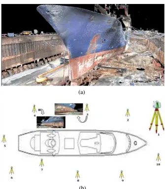
The digitization of a complete ship’s hull, using a stationary grou-nd based LiDAR scanning system, requires scanning from multi-ple positions at appropriate distances. For high resolution scans, as necessary for our application, the distance is kept nominal with slower scanning rates and large scan overlaps. These multiple scans after transformation in a global frame of reference are re-gistered together and filtered to obtain a 3D point cloud of the complete ship hull as shown in Figure 1. The 3D scanning sys-tem, as shown in Figure 1(b) has an integrated 2D camera which allows a colored 3D point cloud i.e. each 3D point with its asso-ciatedR,G&Bvalues.
(a)
(b)
Figure 1. (a) shows the complete 3D point cloud of the ship and the docking area before the filtering phase. Each 3D point is cou-pled with the correspondingR, G& B value. (b) shows the 10 different scanning positions (and different viewing angles), of P20 laser scanner, used to scan the complete ship.
Registration of Multiple Scans
In order to obtain multiple scans the ground based LiDAR scan-ner is placed at different positions all around the ship to ensure full coverage at suitable resolution. The scans are taken such to ensure some overlapping to facilitate the registration process as shown in Figure 1(b). In order to further aid the process, addi-tional targets are also placed all around the ship. The scans are registered, one by one, using a standard ICP algorithm (Besl and McKay, 1992). In order to satisfy the equations, it is ensured that at least 3 common targets are visible in each successive scan.
4. DETECTION OF CORROSION SPOTS
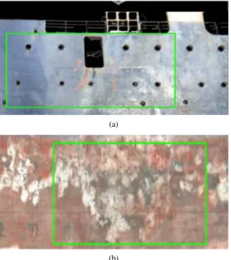
conducted within this selected zone automatically. Although it is possible to analyze the complete ship’s hull all at once, this ma-nual selection of smaller zones of the hull (a common industrial practice) allows the user/expert to quickly and efficiently identify the zone of interest (with larger chance of corrosion spots) for fur-ther processing and prevents wasting resources on less interesting parts.
(a)
(b)
Figure 2. The two images show the zones selected by the user. (a) shows a zone with minor corrosion whereas (b) shows a zone with dominant corroded area.
As the corrosion spots are usually more apparent as visual defects (change in color, intensity, etc.) and less of physical deformation (bending, breaking, etc.), the color information plays an impor-tant role in the detection process. This is also supported by the fact that usually the ship’s hull itself is mono color with very little variation and so corrosion spots are easily visible.
As theR,G,B(Red, Green and Blue) color values are prone to lightning variation, they are converted intoHSV(Hue, Saturation and Value) color space, for each 3D point. This conversion sepa-rates the color component from the intensity component. Also, the intuitiveness of theHSVcolor space is very useful because we can quantize each axis independently. Wan and Kuo (Wan and Kuo, 1996) reported that a color quantization scheme based onHSVcolor space performed much better than one based on
RGB color space. The component, invariant to the lightening conditions, is then analyzed. It is referred to in this paper as the color component as it provides more stable color information. Based on the description presented in (Hughes et al., 2013), the following equations were used for the conversion.
h′=
( (G−B)
δ ifR=M AX 2+(B−R)
δ ifG=M AX 4+(R−G)
δ ifB=M AX
H =h′×60◦, S= M AX−M IN
M AX , andV =M AX HereM AX = max(R, G, B),M IN = min(R, G, B),δ =
M AX−M IN andH, S, V are the corresponding point of
R, G, B, in theHSVspace. Also, to be noted that the norma-lized values ofR, G, Bare used, i.e.R, G, B∈
0. . .1 , and so as a resultH ∈
0. . .360◦
andS, V ∈ 0. . .1
. In case ofR = G = B = 0, H is undefined, hence it is assumed to be−1. After the conversion, the color component is then used in our analysis. Two different techniques are proposed to detect corrosion spots depending on the type of zone selected. They are explained as follows.
4.1 Histogram based Detection
If the selected zone has a majority of non-corroded area as shown in Figure 2(a) then a histogram distribution based method is used. Similar to 2D image segmentation, the larger non-corroded sur-face is considered as background with corrosion spots as fore-ground.
A histogram is obtained for each channel of the color component in theHSVspace. Based on these histograms upper and lower bounds for the color component (c={H, S}) of the background region (i.e. non corroded region)BUc andB
c
Lrespectively are au-tomatically calculated. Based on the distribution, theBc
UandBcL are calculated by analyzing the dominant peaks as shown in Fig-ure 3. Centered on the highest peak, only the peaks with more than 50% of this maximum height are considered for the deter-mination of the cutoff region (1)&(2). Once the upper and lower bounds are determined, the 3D points belonging to the corroded region are segmented using (3), as shown in Figure 4.
BUc =H c max+
m+ X
i
Hbinc i (1)
BLc =H c max−
m−
X
i
Hbinc i (2)
Pi∈
(
Non corroded region if BLc ≤P c i ≤B
c U
Corroded region if Pic> BUc orPic< BLc (3)
HerePi is theith3D point in the selected zone whilePicvalue of its color component. Hmaxc is the value corresponding to the maximum peak in the distribution, while Hc
bini is the bin size of theith
peak for the color componentc. m+andm−are the
number of peaks considered in the cutoff region along the+ve
and−vedirections as shown in Figure 3.
The 3D points belonging to the corroded region are then clustered for further analyses as explained in Section 5..
4.2 Threshold based Detection
If the selected zone is heavily corroded as shown in Figure 2(b) then the histogram based method is not useful as the predominant background (i.e. non corroded area) is not readily available and we cannot base our model on the dominant corroded zone due to a lot of variation in the color components. Thus, we employ an adaptive threshold based method in which a smaller sample vol-ume is used to calculate the upper and lower boundsBcUandB
(a)
(b)
Figure 3. (a) and (b) show the histogram distribution forHand
S respectively for 3D points of a selected zone. Based on the dominant peaks,Bc
UandBLc are automatically selected.
and paint color, etc.) all around. The effect of illumination varia-tion on the color values of 3D points on different parts of the hull due to overlaying shadows, reflections, etc., is already catered for by separating the intensity and the color component by conver-ting intoHSVcolor space and using only the color component for the analysis. OnceBc
UandBLc are calculated using (4)&(5), the 3D points belonging to the selected zone are segmented using (3).
BcU=Psc+ 3
p
σc
s2 (4)
BLc =Psc−3
p
σc
s2 (5)
HerePc
s is the mean value of the color componentcof all the 3D points in the sample zone, whileσcs2is the variance respectively.
The 3D points belonging to the corroded region are segmented out as shown in Figure 4 and further analyzed as explained in the next section.
(a)
(b)
(c)
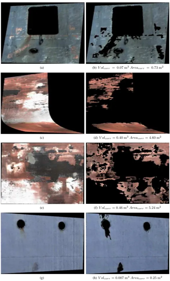
Figure 4. (a) shows the colored 3D point cloud of a small part of a selected zone. (b) shows the corroded region segmented out after detection while in (c) we find the 3D point cloud with the corroded region extracted out.
5. ANALYSES AND ESTIMATION OF THE CORRODED REGION
In order to analyze the corroded region, the 3D points belong-ing to these regions are first extracted out (as shown in Figure 4) and then clustered together using ak-means clustering algorithm as presented in (Zhou and Liu, 2008). The initialkclusters are selected randomly and the algorithm minimizes the dissimilarity measure between all 3D points and their respective associated cluster centroids. It uses the objective function defined as:
J=
k
X
j=1 n
X
i=1
kPij−C j
wherekPij−Cjk2is a chosen distance measure (Squared Eu-clidean distance) between a 3D pointPijand its associated clus-ter centre Cj
. This distance measures the dissimilarity of the 3D points to their respective associated cluster centers. Based on the clusteredn3D points, new centroids are estimated as the barycenters of the clusters and the process is repeated until the centroids seize to move.
Figure 5. Estimation ofV olcorrandAreacorrfor the 3D points of the corroded part contained in each adapted Voxel.
Estimation of Corroded Region
Once the 3D points are clustered, the total volume and surface area of the corroded regions are determined. This helps in esti-mating the amount of work and material (such as paint) required for renovation/overhauling of the ship’s hull.
As the clusters formed of different corroded regions are of vary-ing shapes and sizes, it is difficult to calculate the exact surface area and volume. Hence, we use a finite element method by divid-ing these regions into finite number of very small 3D voxels (Ai-jazi et al., 2013). Although the maximum voxel size is limited to 5cm3, the actual voxel size varies depending on the maximum and minimum values of the constituting 3D points along each of the three axes as shown in Figure 5. This way, a certain corroded region may be divided into tens or hundreds of smaller voxels de-pending upon the density and size while the adaptive voxel sizes ensure that the profile of the region is preserved. The volume is then simply calculated as the volume of the bounding cuboid (refitted/adapted voxel). The total volume is then the sum of all individual voxels as shown in (11).
In order to calculate the surface area, an arbitrary plane is de-termined by calculating the best-fit plane through the 3D points contained in the refitted/adapted voxel using planar regression of data as presented in (Fern´andez, 2005). A best-fit plane is defined with the equation:
(xi−x) =B(yi−y) +C(zi−z) (7)
wherex,y, andzare the respective mean values ofX,Y, andZ
coordinates of all points. To find the equation of the best-fit plane for a given set of points, Press et al. (Press et al., 2007) present the following equations that are solved forBandC:
X
((xi−x)(yi−y)) =
BX(yi−y)2+C
X
((yi−y)(zi−z)) (8)
X
((xi−x)(zi−z)) =
BX((yi−y)(zi−z)) +C
X
(zi−z)2 (9)
The result of the regression is a plane that passes through a point with coordinates(x, y, z)and is returned in the form of a vector normal to the best-fit plane. The equations in (Press et al., 2007) are corrected to deal with traces/residue, by replacing (7) with the following definition:
(yi−y) =A(xi−x) +C(zi−z) (10)
and modifying (8) and (9) accordingly.
These 3D points contained in the refitted/ adapted voxel are then projected on this plane as shown in Figure 5 and area is calculated as the area of the bounding rectangle. The total surface area is again the sum of individual areas as presented in (11) and (12).
V olcorr= N
X
i=1
(|Xmaxi −Xmini |.|Ymaxi −Ymini |.|Zmaxi −Zmini |)
(11)
Areacorr= N
X
i=1
(|Xmaxpi −Xminpi |.|Ymaxpi −Yminpi |) (12)
HereN is the total number of voxels,X, Y, Z andXP , YP are the 3D and 2D-projected coordinates of the points respec-tively. As the voxel sizes are very small, the volume and surface area estimations of the corroded region,V olcorr andAreacorr respectively, are quite accurate.
6. EXPERIMENTS, RESULTS AND EVALUATION
The proposed method was evaluated on real data.700×1063D points were obtained after scanning a ship (120 mlong and20 m
wide) using Leica’s P20 laser scanning station as shown in Fig-ure 1. Multiple scans were obtained from ten different locations, all around the ship, and then registered together as explained in Section 3..
Different zones on the ship’s hull were selected and the corro-ded regions were detected and then analyzed using our method. Some qualitative results are presented in Figure 6. The figure shows that the method is able to successfully segment out most of the corroded regions. As the method is non parametric (does not rely on particular shapes and sizes) it is able to segment corro-ded regions of different shapes and sizes. For quantitative results, some of these zones were manually segmented to obtain ground truth. The detection results are presented in Table 1 using diffe-rent standard evaluation metrics as described in (Vihinen, 2012). The analysis was conducted with 3D points.
Although, all these metrics are commonly used to evaluate such algorithms,MCC(Matthews Correlation Coefficient) is regarded as most balanced measure as it is insensitive to different class sizes (like in our application sometimes the number of points be-longing to the corroded regions are significantly less or more than that of the non-corroded regions).
TheMCC, like the other measures, is calculated based on the count of the true positives (i.e. correct detection of 3D points be-longing to corroded region), false positives, true negatives, and false negatives. A coefficient of+1represents a perfect predic-tion,0no better than random prediction and−1indicates total disagreement. The detailed results including overall accuracy
Table 1. Detection results using different standard evaluation metrics.
Metrics
Results
ACC
Accuracy
0.881
PPV
Positive Predictive Value
0.911
NPV
Negative Predictive Value
0.870
FDR
False Discovery Rate
0.088
F
1F
1measure
0.902
MCC
Matthews Coefficient Correlation
+0.690
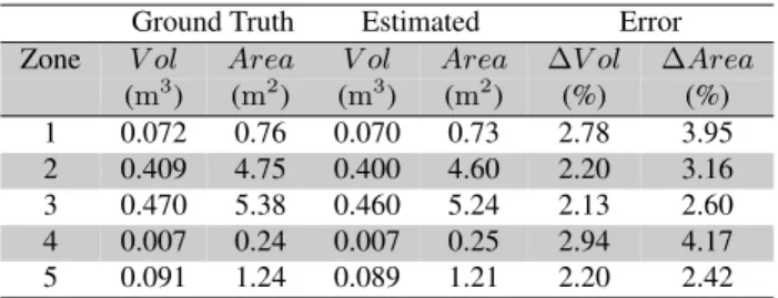
Table 2. Evaluation of volume and surface area estimation.
Ground Truth Estimated Error
Zone V ol Area V ol Area ∆V ol ∆Area
(m3) (m2) (m3) (m2) (%) (%)
1 0.072 0.76 0.070 0.73 2.78 3.95
2 0.409 4.75 0.400 4.60 2.20 3.16
3 0.470 5.38 0.460 5.24 2.13 2.60
4 0.007 0.24 0.007 0.25 2.94 4.17
5 0.091 1.24 0.089 1.21 2.20 2.42
demonstrate the efficacy of the proposed method. It is also ob-served that thePPVis generally found higher thanNPVwhich suggests that the method is more conservative and is more likely to detect corroded zones once highly certain otherwise it does not. Hence, false positives are usually less than false negatives.
The estimation ofV olcorrandAreacorrby the proposed method was also evaluated. Estimated values for five different zones were compared with the corresponding ground truth. The ground truth was obtained by manual labeling of corroded zones followed by Volume and Surface Area calculation based on the equal distribu-tion of 3D points using a 3D CAD software. This supposidistribu-tion of equal distribution is justified by the fact that the sizes of the se-lected zones were relatively small and the position of the scanner was fixed. This ensures that there is minimal to no variation in the point density in the selected zone. The results are presented in Table 2. The results show a relatively small error which demon-strates the efficacy of the method. This error difference between the estimated and the ground truth value also includes the error due to some False PositivesFP(zones wrongly detected as cor-roded zones) as well as False NegativesFN(corroded zones not detected).
We also evaluated the effect of registration errors in the estima-tion ofV olcorrandAreacorr. For this analysis, multiple scans of a particular zone were registered with small but different tration errors. The results, presented in Table 3, show that regis-tration errors play an important part in the detection and analysis of corroded regions as this effect the estimation of the dimension and magnitude of the corroded regions. This may in turn result in higher or lower estimation of repair costs (in terms of material required such as paint, man hours and other processes, etc.).
7. CONCLUSION
In this work a new method for automatic detection and analysis of surface defects such as corrosion spots of different shapes and sizes, on large ship hulls is presented. In the proposed method multiple scans from different positions around the ship are re-gistered together to form a complete 3D point cloud. The R,
Table 3. Effect of registration errors in the estimation ofV olcorr andAreacorr.
Registration Error V ol Areacorr ∆Areacorr
Zone (mm) (m3) (m2) (%)
1 1 0.089 1.21
2 4 0.093 1.28 ⇑6%
3 13 0.103 1.41 ⇑16%
G,Bvalues associated with each scan, are converted intoHSV
space to separate out the illumination invariant color component from the reflectance intensity. Using this color component, dif-ferent surface defects such as corrosion spots of difdif-ferent shapes and sizes are automatically detected, within a selected zone, us-ing two different methods dependus-ing upon the level of corro-sion/defects. These detected corrosion spots are then analyzed and accurately quantified. The different aspects of the method are thoroughly evaluated on real data using different standard evalua-tion metrics and the results clearly demonstrates the efficacy as well as the applicability of the proposed method.
This method not only helps to increase the reliability but also the accuracy of the detection and estimation of these defective regions, as compared to manual inspection that is currently the standard practice. As a result, this could definitely lead to better estimation of cost and optimization of different repair and main-tenance processes in the shipping industry.
ACKNOWLEDGMENTS
The work reported in this paper is supported and performed as part of the French project FUI-17 ROMAPE lead by SAMES TECHNOLOGIES, France. The authors would also like to thank DAMEN SHIPREPAIRDUNKERQUE, France, for their coopera-tion during data acquisicoopera-tion.
REFERENCES
Aijazi, A. K., Checchin, P. and Trassoudaine, L., 2013. Segmen-tation Based Classification of 3D Urban Point Clouds: A Super-Voxel Based Approach. Remote Sensing 5(4), pp. 1624–1650.
Armesto, L., Tornero, J., Herraez, A. and Asensio, J., 2011. In-spection system based on artificial vision for paint defects detec-tion on cars bodies. In: Robotics and Automadetec-tion (ICRA), 2011 IEEE International Conference on, pp. 1–4.
Besl, P. J. and McKay, N. D., 1992. A Method for Registration of 3-D Shapes. IEEE Trans. Pattern Anal. Mach. Intell. 14(2), pp. 239–256.
Biskup, K., Arias, P., Lorenzo, H. and Armesto, J., 2007. Appli-cation of terrestrial laser scanning for shipbuilding. In: IAPRS Workshop on Laser Scanning, pp. 56–61.
Fern´andez-Isla, C., Navarro, P. J. and Alcover, P. M., 2013. Auto-mated Visual Inspection of Ship Hull Surfaces Using the Wavelet Transform. Mathematical Problems in Engineering.
Fern´andez, ´O., 2005. Obtaining a best fitting plane through 3d georeferenced data. Journal of Structural Geology 27(5), pp. 855 – 858.
Han, Y. and Shi, P., 2007. An adaptive level-selecting wavelet transform for texture defect detection. Image and Vision Com-puting 25(8), pp. 1239 – 1248.
(a) (b)V olcorr = 0.07 m3Areacorr = 0.73 m2
(c) (d)V olcorr= 0.40 m3Areacorr= 4.60 m2
(e) (f)V olcorr= 0.46 m3Areacorr= 5.24 m2
(g) (h)V olcorr= 0.007 m3Areacorr= 0.25 m2
Kumar, A., 2008. Computer-Vision-Based Fabric Defect Detec-tion: A Survey. Industrial Electronics, IEEE Transactions on 55(1), pp. 348–363.
Kumar, A. and Pang, G., 2002. Defect detection in textured ma-terials using Gabor filters. Industry Applications, IEEE Transac-tions on 38(2), pp. 425–440.
Lin, H.-D., 2007. Automated visual inspection of ripple de-fects using wavelet characteristic based multivariate statistical ap-proach. Image and Vision Computing 25(11), pp. 1785 – 1801.
Navarro, P., Iborra, A., Fern´andez, C., S´anchez, P. and Suard¨ıaz, J., 2010. A sensor system for detection of hull surface defects. Sensors pp. 7067–7081.
Ngan, H., Pang, G. and Yung, N., 2010. Performance Evaluation for Motif-Based Patterned Texture Defect Detection. Automation Science and Engineering, IEEE Transactions on 7(1), pp. 58–72. Ngan, H. Y., Pang, G. K. and Yung, N. H., 2011. Automated fabric defect detection – a review. Image and Vision Computing 29(7), pp. 442 – 458.
Ngan, H. Y., Pang, G. K., Yung, S. and Ng, M. K., 2005. Wavelet based methods on patterned fabric defect detection. Pattern Recognition 38(4), pp. 559 – 576.
Ortiz, F., Pastor, J. a., Alvarez, B., Iborra, A., Ortega, N., Rodr´ıguez, D. and Conesa, C., 2007. Robots for hull ship clean-ing. In: IEEE International Symposium on Industrial Electronics, pp. 2077–2082.
Press, W. H., Flannery, B. P., Teukolsky, S. A. and Vetterling, W. T., 2007. Numerical recipes 3rd Edition: The Art of Scientific Computing. 3rd edn, Cambridge University Press, New York, NY, USA.
Review of Maritime Transport, 2014. http://unctad.org/en/ PublicationsLibrary/rmt2014 en.pdf.
Sezgin, M. and Sankur, B., 2004. Survey over image thresholding techniques and quantitative performance evaluation. Journal of Electronic Imaging 13(1), pp. 146–168.
Truchetet, F. and Laligant, O., 2008. Review of industrial ap-plications of wavelet and multiresolution-based signal and image processing. Journal of Electronic Imaging 17(3), pp. 031102– 031102–11.
Tsai, D.-M. and Huang, T.-Y., 2003. Automated surface inspec-tion for statistical textures. Image and Vision Computing 21(4), pp. 307 – 323.
Vihinen, M., 2012. How to evaluate performance of prediction methods? Measures and their interpretation in variation effect analysis. BMC Genomics 13(Suppl 4), pp. S2.
Wan, X. and Kuo, C. J., 1996. Color distribution analysis and quantization for image retrieval. In: Storage and Retrieval for Image and Video Databases (SPIE), pp. 8–16.
Wong, W., Yuen, C., Fan, D., Chan, L. and Fung, E., 2009. Stitch-ing defect detection and classification usStitch-ing wavelet transform and BP neural network. Expert Systems with Applications 36(2, Part 2), pp. 3845 – 3856.
Xie, X., 2008. A Review of Recent Advances in Surface Defect Detection using Texture analysis Techniques. Electronic Letters on Computer Vision and Image Analysis.
Zheng, H., Kong, L. and Nahavandi, S., 2002. Automatic inspec-tion of metallic surface defects using genetic algorithms. Journal of Materials Processing Technology 125–126, pp. 427 – 433.