Evaluation of Macrobend Loss on Long
Distance Optical Ground Wire
M. F. M. Salleh 1,2,*, Z. Zakaria 1,**
1
Centre for Telecommunication Research & Innovation (CeTRI),
Faculty of Electronic & Computer Engineering, Universiti Teknikal Malaysia Melaka (UTeM), Hang Tuah Jaya, 76100, Durian Tunggal, Melaka, Malaysia
2
Telecommunication Infrastructure Management, Southern Regional Operation, ICT Division, Tenaga Nasional Berhad (TNB), Jalan Mengkibol, 86000, Kluang, Johor, Malaysia
*
**
Abstract—Bend loss is a kind of loss that contributes to the power attenuation which is caused by the bending of optical fiber. For long distance optical fiber, bending might occur at joining point as there are many joining points along the link. Studies related to bend loss always relate the effect of bend radius on bend loss value. There is no study that relates the value of loss that can be affected by other factors like the natural environmental conditions. In this study, the evaluation of bend loss on existing long distance Optical Ground Wire (OPGW) was studied since the cable was exposed to any climate condition.
Keyword-Evaluation, Bend Loss, Attenuation, Optical Ground Wire (OPGW), Optical Time-Domain Reflectometer
I. INTRODUCTION
Optical fiber attenuation is found increasing as time goes. Bending loss is one of the losses that contribute to the lack of fibre performance [1] and increase the overall power attenuation of a particular optical fiber [2]. Bending of optical fibre can be mostly found at termination points and joining points. For long distance fiber cable, there are many locations of joining. As shown in Fig. 1, there is bending of optical fiber inside the joint closure.
Fig. 1. Bending of optical fibre in joint closure
Fig. 2. Bending of optical fibre in joint closure
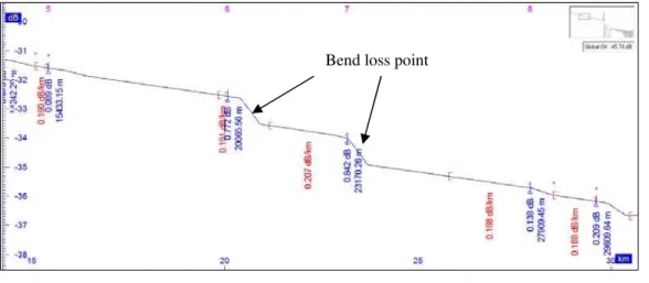
Losses that are detected as in Fig. 2 probably due to splice loss or bending loss. In order to decide if those losses are due to the bending of fiber or splicing, test with two different wavelengths has been conducted and compared.
The proper experiments have been conducted to evaluate the bend loss value that occurs along the optical fiber. In this study, the experiment has been conducted on existing OPGW cable to monitor the activity of bend loss as time goes.
II. BEND LOSS &ATTENUATION
Bend loss is a type of loss that is caused by bending of optical fiber. The value of loss depends on the Mode Field Diameter (MFD, wavelength and bending radius. The attenuation will be affected by bend loss [3] so that the study on bend loss becomes important. In addition, this type of loss can be rectified by releasing the bending [6].
A. Bend Loss Factor
The single most important factor that determines the susceptibility of a fibre to bending that induces loss is the Mode Field Diameter (MFD) [10] [6]. MFD represents the area in which the light goes through and includes the core and a part of the cladding. A smaller mode field diameter indicates that light is more tightly confined to the fibre centre and, therefore is less prone to leakage when the fibre is looped [6]. Fig. 3 shows the relationship of light power and MFD where the diameter of core and the wavelengths are the important parameters in determining the sensitivity of bend loss.
Fig. 3. The relationship between light and MFD [6]
The total number of modes supported in a curved, multimode fibre is therefore related to the index profile, the propagating wavelength, and the radius of curvature as shown in Equation 1.
= − ∆ +
Where N∞ is the number of modes supported in a straight fibre, α defines the index profile, Δ is the core-cladding index difference, n2 is the cladding index, k = 2π/λ and R is the radius of curvature of the bend [5].
Single mode fibre has a larger mode field diameter at 1550 nm than at 1310 nm and at 1625 nm than at 1550 nm. Larger mode fields are sensitive to lateral offset during splicing, but they are more sensitive to losses incurred by bends during installation or in the cabling process [6].
B. Wavelengths Sensitivity on Bending
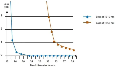
1550nm is more sensitive to bends in the fibre than 1310nm. By measuring the same fibre, which includes splices and connectors, using those two wavelengths, the potential bending optical fibre could be determined. For a given event (splice or connector), if there is no bend, the loss measurement shall be about the same at any wavelength. If there is a large difference more than 0.2 dB between the two wavelengths, this is due to bend [5]. Fig. 4 shows the sensitivity of different wavelengths on macro bend. The variable used is bend radius.
Fig. 4. 1310 nm vs. 1550 nm on diameter of bend [2]
OTDRs are the ideal tools for detecting and locating bends in a fibre link [6]. As bend is sensitive to longer wavelengths but not for shorter wavelengths, most of the operators use two wavelengths from OTDR to test the fibre links. The wavelengths that commonly used for detecting bend loss are 1310 nm and 1550 nm. These two wavelengths will be used in this paper for that purpose. For future analysis, bending loss should be taken between 1310 nm and 1625 nm, or between 1550 nm and 1625 nm, which are relevant wavelengths for DWDM testing.
C. Critical Radius
When the bending reaches a critical radius of curvature, Rc, usually, the loss due to bending can be neglected, and Rc is defined by [7] and [8] as Equation 2.
= .
where Rc is the critical radius of bending, n2 is the refractive index of the clad and NA is the numerical aperture of the fiber and λ is the wavelength.
III.EXPERIMENTS
The experiments have been done on the existing OPGW that is installed on high voltage transmission towers. The length of fibre cable is 54.554km and has 24 joining points. The scope of this experiment is to monitor the occurrence of bend loss along the fiber link and to see the trend. The test has been done three times in a duration of 10 months by analysing the losses that are detected by OTDR.
A. Loss Event
TABLE I. Losses detected by 1310 nm and 1550 nm wavelength for Sample 1in Experiment I
Wavelength
1310 nm 1550 nm Distance
(m)
Loss (dB)
A Distance (m)
Loss (dB) B
11039.38 0.171 11167.81 0.194 14424.66 0.307 14470.89 0.161
20398.97 0.892
23214.04 1.227
30082.20 0.355 30071.92 0.703 42272.27 0.094 42087.33 0.104
47897.27 0.356
54631.86 End 54647.27 End
As discussed in [6], if the different is less than 0.2dB, the event is considered as splice loss or other losses than bend loss. From these data, bend loss can be detected and differentiated from other losses.
B. Determining Bending Loss
The Optical Time Domain Reflectometer (OTDR) uses the effects of Rayleigh scattering and Fresnel reflection to measure the characteristic of an optical fibre [11] [12] [13]. By sending a pulse of light into a fibre and measuring the travel time and strength of its reflections from points inside the fibre, it produces a characteristic trace, or profile, of the length vs. returned signal level on a display screen.
When the 1550 nm wavelength was introduced and added to the 1310 nm transmission wavelength, the bending effect was analysed. The bending of optical fibre will give optical power loss that affects longer wavelength more than shorter wavelength [14] and [15] as shown in Fig. 5.
However, the losses that are detected by 1550 nm wavelength in optical fibre of OPGW that is already installed on a high voltage transmission tower is not necessarily due to the bending of optical fibre. To detect the bend loss, the value of losses for 1310 nm and 1550 nm wavelength at each location is compared. As studied by [6], the bend loss that will cause the loss captured by 1550 nm will be higher than losses captured by 1310 nm by at least 0.2 dB.
Fig. 5. 1310 nm vs. 1550 nm at same point.
Where y is the loss captured by 1550 nm wavelength and x is loss captured by 1550 nm wavelength. As discussed in [6], losses caused by splice loss or other losses are detected by any wavelength within the margin of less than 0.2dB, the extra loss is considered as caused by bending. In this study, the margin of loss will be used as parameters since no data of splice loss have been provided.
C. Monitoring
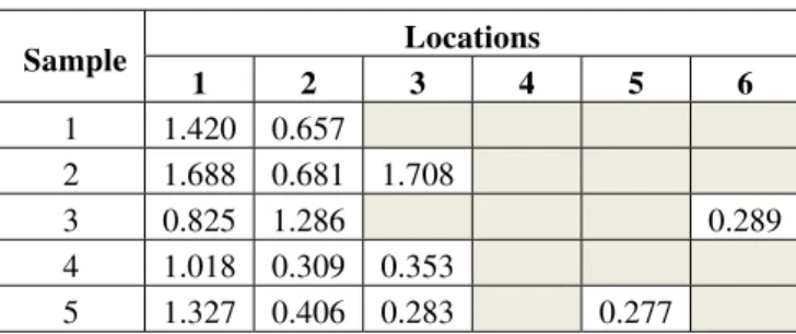
From the conducted experiments, there were six locations of bending loss found. As discussed earlier, the locations were found by comparing the value of loss between 1310 nm and 1550 nm and the bend loss will be determined if the difference between the loss values at the same distance is more than 0.2dB. The different loss value between 1310 nm and 1550 nm as the results of Experiment I is presented as in Table II.
1310 nm
1550 nm
X dB
TABLE II. Bend loss determination from Experiment I
Sample Locations
1 2 3 4 5 6
1 0.722 0.748 0.293 2 1.095 1.091 0.315
3 1.338 0.538 0.796
4 1.761 0.248
5 2.331 1.247 0.850 0.850 0.850
There were four locations of bend loss found in Experiment I. There was no bend loss detected at location 5 and 6. The second experiment then took place 6 months later showed different value of losses and new bend losses were found at different location. The results are shown as in Table III.
TABLE III. Bend loss determination from Experiment II
Sample Locations
1 2 3 4 5 6
1 1.420 0.657 2 1.688 0.681 1.708 1.708 3 0.825 1.286 0.289 4 1.018 0.309 0.353 5 1.327 0.406 0.283 0.277
The values of losses have varied in 6 months but the bend losses remained to occur at some places but with different values. Another experiment was done 4 months after the Experiment II and the results are shown as in Table IV.
TABLE IV. Bend loss determination from Experiment III
Sample Locations
1 2 3 4 5 6
1 1.584 0.630 1.729 0.266 0.266 0.266
2 0.842 1.177 0.348 0.306 3 0.857 0.242 0.389
4 1.321 0.406 0.347 0.227 5 1.782 0.553 0.733
There is no more bend loss detected at location 4 and 6 while new bend losses are detected at location 5 on another samples of fiber core. These variation of result obtained from Experiment I to Experiment III show that the bend losses varied in values.
IV.DISCUSSION
The bend loss can occur inside the joint closures due to the bending of optical fibre either caused by human error or natural activities. The bending losses on long distance optical fibres were detected by comparing the value of losses that are captured at a particular point using two different wavelengths. The minimum difference of value is set at 0.2 dB in order to decide if there is bending loss at that point. Three experiments have been done in 10 months to monitor the variation of losses that occured inside the joint closures. The conducted experiments have shown that the value of losses have varied from time to time inconsistently.
The locations of bend losses that were found in three experiments matched with the location of joint closures. The value of losses varied from time to time and was hard to predict. In general, the bending of optical fiber in joint closure will not cause loss since the radius of bending is large enough to avoid bend loss. Furthermore, the bending of optical fiber inside joint closures remains at its form with permanent radius. Even the bending of optical fiber inside the joint closure contributes to the loss; there should be no significant variation of loss as obtained from three experiments.
The results of these experiments that are presented in this paper have a significant contribution especially to telecommunication industries. This paper has shown that the variance of bend loss occur on existing optical fiber. Since the losses that occur due to bending keep increasing and occurring, further study on the actual factor that cause the bending to occur has to be done. From deep study which is in shorter period between each experiment, the pattern of loss can be observed. In addition, by doing proper investigation, the repetitive bending can be avoided so that the value of every dark fiber becomes more reliable.
V. CONCLUSION
The method of detecting bend loss by comparing the value of loss between 1310 nm and 1550 nm wavelength was successful done. Experiments done in 10 months have shown that the value of bend losses varied from time to time. These results have proven that the bend loss might be affected by several factors rather that the radius of bending. These findings are very important so that any study related to bend loss will consider other factor like the environment temperature. This is because, in the real situation of the existing fiber cable, the cable is exposed to any weather or climate condition.
ACKNOWLEDGMENT
Many thanks to Universiti Teknikal Malaysia Melaka (UTeM) for supporting this work under the research grant, FRGS (RACE)/2012/FKEKK/TK02/02/1 F00147 and to Tenaga Nasional Berhad, Malaysia for allowing the authors to conduct the experiments on its existing dark fibers.
REFERENCES
[1] Yu Zhi, X., and Wang Hong, X., 2012. Analysis of Theory and Experiment on Bend Loss Research by OTDR, Wuhan : Electronic College of Engineering.
[2] Jenny, R., 2000. Fundamentals of Fiber Optics: An Introduction for Beginners, Volpi Manufacturing USA Co., Inc., pp. 1-22. [3] Hakim, S. A., 2010. Attenuation and Dispersion in Optical Communication, Dhaka : Bangladesh Communications Company Limited. [4] Abramczyk, H., 2008. Dispersion Phenomena in Optical Fibers, Poland : Technical University of Lodz.
[5] Potter, B. G., 2010. Module 3 - Attenuation in Optical Fibers, Material Science and Engineering Dept, University of Arizona, pp. 1-16. [6] JDSU, 2007. White Paper: Macrobend Detection Using an OTDR, JDS Uniphase Corporation, pp. 1-4
[7] Zendehnam, A., Mirzaei, M., Farashiani, A., and Horabadi Farahani, L., 2010. Investigation of bending loss in a single-mode optical fibre, Pramana Journal of Physics., 74(4), pp. 591-603.
[8] Dutton, H. R. J., 1998. Understanding optical communications, IBM Corporation, International Technical Support Organization, 1, pp. [9] Lietaert, G., 2009. White Paper: Fiber Water Peak Characterization, JDS Uniphase Corporation, pp. 1-8.
[10] Corning, 2001. “OTDR Gainers” - What Are They?, Application Note, Corning Incorporated ,USA
[11] Vita, P. D., and Rossi, U., 1988. The backscattering technique: Its field op applicability in fiber diagnostics and attenuation measurement, Opt. Quantum Electron., 12, pp. 17-22.
[12] Collin, R. E., 1981. Rayleigh Scattering and Power Conservation, IEEE Transactions on Attennas and Propagation, AP-29(5), pp. 795-798.
[13] Fermann, M. E., Poole, S. B., Payne, D. N., and Martinez, F., 1988. Comparative Measurement of Rayleigh Scattering in Single-Mode optical Fibers Based on an OTDR Technique, Published in Journal of Lightwave Technology, Vol 6, Issue 4, pp. 545 – 551.
[14] Robertson, B., 2005. Optical Loss Testing Concepts Application Note, Kingfisher International
[15] Ryer, A. D., 1998. Light Measurement Handbook, International Light Inc, Newburyport, MA, 2, pp. 9-12.
AUTHORPROFILE
MOHAMAD FAZLI MOHAMAD SALLEH, CFOT, CFOS, BEM, Grad IEM - was born in Malaysia in 1986. He received the B. Eng. in Electrical and Electronic Engineering from the Universiti Tenaga Nasional Malaysia in 2009 and currently is final year student of Master Degree in electronic communication at University Teknikal Malaysia Melaka. He is a telecommunication engineer at Tenaga Nasional Berhad (TNB) Malaysia from 2010 till now. He manages the operation of telecommunication network and services for southern Malaysia which include 29 high voltage power substations from 132kV to 500kV and 1,816 km of fiber optic. He also a member of Fiber Optic Association (FOA) and certified as trainer and specialist.