Tribology
in
Industry
www.tribology.fink.rsAnalyzing
the
Surface
Roughness
Effects
on
Piston
Skirt
EHL
in
Initial
Engine
Start
‐
Up
Using
Different
Viscosity
Grade
Oils
M. Gulzar
a, S.A. Qasim
a, R.A. Mufti
aaCollegeofElectricalandMechanicalEngineering,NationalUniversityofSciencesandTechnology(NUST),Pakistan.
Keywords:
EHL Pistonskirt Flowfactor Asperity Hydrodynamic Vogelpohlparameter
A B S T R A C T
Theabsenceof fully developedfluid filmlubrication between Piston andLinersurfacesisresponsibleforhighfrictionandwearatinitial engine start‐up. In this paper flow factor method is used in two dimensional Reynolds’ equation to model the effects of surface roughness characteristics on Piston Skirt elastohydrodynamic lubrication. The contact of surface asperities between the two surfacesanditsaftereffectsonEHLofpistonskirtisinvestigated.For thispurpose,twodifferentgradeoilsareusedtoshowthechanging effects of viscosity combined with surface roughness on different parametersincludingfilmthickness,eccentricitiesandhydrodynamic pressures. The results of the presented model shows considerable effectsonfilmthicknessofroughpistonskirt,hydrodynamicpressures andeccentricitiesprofilesfor720degreescrankangle.
© Published by Faculty of Engineering
Corresponding author:
M.Gulzar
CollegeofElectricalandMechanical Engineering,NationalUniversityof SciencesandTechnology(NUST), Pakistan
E‐mail:[email protected]
1. INTRODUCTION
)n initial engine start‐up the piston and liner surfaces are not separated by an oil film which causes maximum wear and friction between the two sliding surfaces. The effects of physical contacts between the asperities of surfaces which are in relative motion must be included in lubrication model to get a better understanding of rheology. )n lubricated interacting surfaces, the surface topography characteristics become more significant because they have a major effect on generation of a continuous lubricant film and in case of high amplitude of asperities in comparison to lubrication film thickness,
there is an increased probability of direct contacts among asperities which can results in adhesive wear [ ].
(amilton, Wallowit and Allen [ ] were the pioneer for taken into account the roughness effects on lubrication phenomenon and their work dates back to . They developed a theory of hydrodynamic lubrication between two parallel surfaces with surface roughness on one or both of the surfaces. The classical theory of lubrication does not predict the existence of any pressure in case of sliding flat parallel surfaces. Surface roughness helps in the pressure build‐up between the two interacting
surfaces, so provide a load support and avoid collapse of two bodies. Early research integrated the roughness amplitude with the film thickness and developed the modified one dimensional Reynolds s equation but the presented models did not cover different regimes and asperity contacts and limited to one dimensional changes. )n this prospective an exception is given in and by Patir and Cheng [ ‐
]. Since the contacting surfaces have an inherent roughness, so Lambda Ratio or Tallian Parameter will be used as the defining parameter between different lubrication regimes [ ]. )n recent research the film thickness parameter λ range has been investigated and redefined for different lubrication regimes [ ]. The P.C. model was suitable for values of film thickness ratio λ > .e; full film lubrication regime where asperity contacts were neglected [ ‐ ]. To minimize the wear and friction losses the elastohydrodynamic lubrication E(L model is presented where λis much lesser than a value of [ ]. Thus the flow factor model provided by J.(. Tripp [ ] is numerically modelled for hydrodynamic lubrication at initial engine start‐up. Greenwood‐Tripp asperity contact model is used to incorporate the asperity contact forces and asperity contact friction force in E(L between the sliding surfaces [ ]. To incorporate the isotropic behaviour the Peklenik number [ ] is defined for the rough surfaces which are generated by normal distribution using Fast Fourier Transform [ ‐ ]. )n rheology a number of parameters affect the lubrication film between interacting surfaces. These parameters include piston to bore radial clearance, lubricant viscosities and chemical properties, surface roughness, shear heating, cavitation effects, squeeze film effects, material properties and other operating conditions.
The viscosities of lubricating oils along with characteristics of additives have a significant effect on friction and wear performance of interacting materials [ ]. Thus in this research, isotropic rough piston and skirt surfaces are selected and modelled with high and low viscosity oils. The results are plotted, showing the hydrodynamic and E(L film thickness profiles, dimensionless eccentricities profiles and hydrodynamic pressures at rpm with radial clearance of micron. A comparison of the results for Oil A . Pa.s and Oil B . Pa.s is provided. The results show an
interesting finding, that the considered low viscosity oil Oil A is more suitable to avoid the contact and wear between interacting rough surfaces of piston and liner at initial engine start‐up.
For developing the numerical model following assumptions are taken:
. Lubricant is incompressible and thermal effects are neglected.
. Non‐Newtonian lubricant behaviour is neglected.
. Pressure at the inlet is zero and surfaces are oil‐flooded.
. Lubricant flow is laminar and turbulence effects are neglected.
. Leakage at the sides and edges is neglected.
2. NOMENCLATURE
C = Radial clearance between piston and liner = microns,
Cf= Specific heat of lubricant,
Cg = Distance from piston center of mass to
piston pin = . cm,
Cp = Distance of piston‐pin from axis of piston = cm,
F = Normal force acting on piston skirts,
Ff = Friction force acting on skirts surface,
Ffh = Friction force due to hydrodynamic
lubricant film,
FG = Combustion Gas force acting on the top of piston,
Fh =Normal force due to hydrodynamic pressure
in film,
FIC = Transverse )nertia force due to piston mass,
IC
F~ = Reciprocating )nertia force due to piston
mass,
FIP = Transverse )nertia force due to piston pin mass,
IP
F~ = Reciprocating )nertia force due to piston
pin mass,
Fc = Asperity Contact Force,
Ffc = Friction force due to asperity contact, G = Shear modulus of elastic lubricant,
Ipis = Piston inertia about its centre of mass,
Mf = Friction moment acting on skirt surface,
Mfh = Moment about piston pin due to
hydrodynamic friction,
Mh = Moment about piston pin due to
hydrodynamic pressure, Mc = Asperity Contact Moment,
Mfc = Moment due o friction force of asperity contact,
R = Radius of piston,
U = Piston Velocity,
a = Vertical distance from skirt top to piston‐pin = . m,
b = Vertical distance from skirt top to piston center of gravity = . m,
et = Piston eccentricities at skirts top surface,
eb = Piston eccentricities at skirts bottom surface, ёb = Acceleration of piston skirts bottom eccentricities,
ёt = Acceleration of piston skirts top eccentricities,
h = Film Thickness,
l = Connecting rod length,
mpis = Mass of piston = . kg,
mpin = Mass of piston‐pin = . kg,
p = (ydrodynamic pressure,
r = Crank radius = . m,
ω = Constant crankshaft speed engine speed ,
τ = Shear stress,
A = Oil A viscosity = . Pa.s.,
B= Oil B viscosity = . Pa.s.,
= Connecting rod angle, = Crank angle,
X
,
y= Pressure flow factor along x and y‐axisrespectively,
s
= Shear flow factor,
= combined root mean square rms roughness,1
= rms roughness of piston skirt= . µm,2
= rms roughness of cylinder liner = . µm,3. MATHEMATICALMODEL
3.1EquationsofPistonMotion
The forces and moments are in the form of the force and moment balance equations similar to that defined by Zhu et al [ ]:
f s c h fc fh s c h b t M M M M F F F F F e e a a a
a ( )tan
22 21 22 11 L b m L a m
a11 pin 1 pin 1 a
L b m L a m
a12 pin pin b
(1 ) 21 L b b a m L I a pin
pin
c L I L b b a m
a22 pin ( ) pin d
G IP IC
s F F F
F tan ~ ~
g IC p G
s F C F C
M ~
Using the Greenwood‐Tripp s Asperity Contact Model, the values of Fc, Ffc, Mc and Mfc can be found for E(L regime [ ].
3.2FilmThicknessEquation
The film thickness between the skirts and the liner given by Zhu [ ]:
x L y t e t e x t e C
h t( )cos b( ) t( )] cos
3.3Reynolds’EquationModelling
Modified ‐D Reynolds equation is given as [ ]:
) ( 6 3 2 3 x x h U y p h y L R x p h x S T y x
where
x and
y are Poiseulle or pressure flowThe boundary conditions are defined as [ ]: 0 0 x p x p
p
=0
when x ≤ x ≤ x
0 ) , ( ) 0 ,( p L
p
)n dimensionless form the ‐D Reynolds equation is given by [ , ]:
* * * * * * * * * * * * 3 2 3 x x h y p h y L R x p h x S T y x
Where by J. ( Tripp [ ]:
2
]
/
)][
1
/(
)
2
(
3
1
h
X
y =X(1/)
)
,
(
)
,
(
2 2 2 2 1 2 21
s
s h
s h ( / ) ) 1 ( 3 ) ,
(h 2 h
s
and
is the Peklenik number [ ].)n order to read the pressure profiles conveniently, the Vogelpohl parameter Mv is
introduced [ ]:
5 . 1 * *h p
Mv
The Reynolds equation in terms of the Vogelpohl parameter is given as:
2
2 2
2 2
2
.
(1 / ) ( )
. * . * . * . *
. .
(1 / ) ( )
. * . *
v v x v
y v
v
M R M M
x L y x x
R M
FM G
y L y
where: 2
2 2 2 2 2
2 2 2 2 * * * * 0.75 1.5 * * * * * * * * 1.5 * * * * *
h R h h R h
x L y x L y
F
h h
h R h
x x L y y
h ) * ( * * * * 5 . 1 h x x h G S
21 , 1, , , 2 , , , ,
, ,
1 2 ,
3 , 1, , ,
1 2 ,
4 , 1, , , .
1 2 ,
. .
2. 2. . *
. (1 / *) . *
2. 2. . * . (1 / *)
. *
2. 2.
v i j v i l j v i j l v i j i v i j
i j
v i j v i l j
i j
v i j v i l j i j
i j
R
C M M C M M
L M
C C F
C M M
x
C C F
C M M G
y
C C F
3.4.FilmThicknessinEHLRegime
)n E(L regime the film thickness includes film thickness in the rigid hydrodynamic regime and the elastic surface displacements etc. By considering the bulk elastic deformation, the lubricant film thickness equation takes the following form [ ]
v y f h
heh; (, )
where f( ,y ) is neglected. The differential surface displacement is [ ]:
r dydy y x p E dv ) , ( 1
2
0 2
0) ( )
(x x y y
r
2 2 2 1 2
1 ) (1 ) 1 ( 2 1 1 E v E v E
At a specific point xo,yo the elastic deformation
is [ ]:
a r dxdy y x p E y x v ) , ( 1 ) ,( 0 0
4.RESULTSANDDISCUSSION
The hydrodynamic lubrication and E(L models of the piston skirts at rpm are developed after incorporating the pressure flow and the shear flow factors. Two different oils having viscosity . Pa.s and . Pa.s are used for a comparison and investigating the viscosity effects on different parameters which include film thickness ,eccentricities and hydrodynamic pressure profiles at degree crank rotation cycle.
4.1PistonEccentricities
Eb are plotted against the degree crank rotation cycle. Figure a and b show eccentricity profiles for Oil A at rpm. The results are plotted between a range of and ‐ where the physical contact between the sliding surfaces can occur. At central value the motion is concentric. Figure a shows the dimensionless eccentricity profiles in the hydrodynamic lubrication regime whereas Fig. b shows the similar profiles in the E(L regime.
a b
Fig.1. For Oil A, Dimensionless Eccentricities at
rpm in a (ydrodynamic regime b E(L Regime.
The behaviour is shown for all the four strokes where it can be seen that at the start of cycle the piston and liner axis are concentric then due to the secondary motion the profiles are highly displaced from the centre towards thrust side and non‐thrust side, but for Oil A the physical contact is avoided as shown in Fig. . For Oil B, the dimensionless eccentricities profiles for hydrodynamic and E(L regime are shown in Fig. . Figure a shows that the contact is established at lower surface as line is meeting with ‐ in rigid hydrodynamic regime. (owever in Fig. b the E(L regime shows the physical contact is clearly avoided. This shows that the elastic deformation of asperities help in avoiding the contact between interacting surfaces, thus help in avoiding friction related wear.
Comparison of eccentricities for both oils provides an interesting finding that the low viscosity oil can be more helpful at initial engine start‐up speed of rpm for rigid hydrodynamic regime as well as equally good for E(L regime.
4.2HydrodynamicPressures
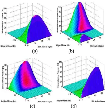
Three dimensional pressure fields and related pressure distribution are plotted for degree crank angle. Figures a , b , c , d show ‐D hydrodynamic pressure profiles at , , and crank angles at rpm.
The positive pressures are developed over the piston skirt and vary as shown in Fig. . )n Fig. a , for Oil A, at degrees crank angle the pressures are biased towards bottom of piston skirt and extended to the middle of piston skirt. The peak pressure occurs at the bottom of piston skirt. )n Fig. b , for Oil A, at degrees crank angle, the pressure field shows that the hydrodynamic pressures are developed at top of piston skirt though a small ridge can be seen at bottom of piston Skirt. The peak pressures are larger than the degrees angle. )n Fig. c , at degrees crank angle, the pressures are shifted towards top of piston skirt. )n Fig. d , at degrees the pressure profile is more steep and developed at bottom of piston skirt showing the end of cycle. For Oil B, in Fig. a , b , c , d show ‐ D hydrodynamic pressure profiles at , , and crank angles at rpm speed.
a b
c d
Fig. 2. For Oil A, ‐D (ydrodynamic pressure fields
at rpm at crank angle a degree b degree c degree d degree.
4.3HydrodynamicandEHLFilmThickness
Figure a shows the maximum and the minimum hydrodynamic film thickness for Oil A at rpm and micron radial clearance. The maximum film thickness is calculated before the application of load and on the other side the minimum film thickness is found after the application of load. The magnitude of minimum film thickness shows whether the film thickness is capable of avoiding the contact between sliding surfaces or not. )n Fig. a , the minimum hydrodynamic film start getting established from start of cycle and reaches at a peak at power stroke and decrease to minimum at end of exhaust stroke and cycle continues. Similar case can be seen for Oil B in Fig. a , but the difference is evident at end of exhaust stroke where a second peak of film thickness can be seen. )n Fig. b and b E(L film thickness profiles are shown. By comparing both profiles, it can be seen that in case of Oil A the E(L film thickness is greater in magnitude for different crank angles as compare to Oil B. Thus Oil A, which is low viscosity oil, will be more helpful in avoiding the contact and wear between rough piston and liner surfaces.
a b
Fig. 3. For Oil A, At rpm a Film thickness
profiles b E(L film.
a b
Fig.4. For Oil B, Dimensionless Eccentricities at
rpm in a (ydrodynamic regime b E(L Regime.
a b
c d
Fig.5. For Oil B, ‐D (ydrodynamic pressure fields at
rpm at crank angle a degree b degree c degree d degree.
a b
Fig. 6. For Oil B, At rpm a Film thickness
profiles b E(L film.
5. CONCLUSION
the rough skirts and the liner surfaces cannot be avoided in the rigid hydrodynamic regime. (owever, for both oils, the rough interacting surfaces deform elastically to generate a sufficiently thick film in the E(L regime. The hydrodynamic pressures shifting occur from top of piston skirt to bottom at degrees crank angle by changing Oil A to Oil B at rpm and micron radial clearance. Comparing both oils for given conditions, Oil A is more suitable to avoid the contact and wear between interacting rough surfaces.
REFERENCES
[ ] N. Diaconu, L. Deleanu, F. Potecasu, S. Ciortan:
The Influence of the Relative Sliding on the Surface Quality, Tribology )n )ndustry, Vol. ,
No. , pp. ‐ , .
[ ] D.B. (amilton, J.A. Walowit, C.M. Allen: Theoryof Lubrication by Microirregularities, Journal of
Basic Engineering, Trans ASME, Vol. , No. ,
pp. ‐ , .
[ ] N. Patir, (.S. Cheng: AnAverageFlowModelfor Determining Effects of Three‐Dimensional RoughnessonPartialHydrodynamicLubrication,
ASME Journal of Lubrication Technology, Vol. , No. , pp ‐ , .
[ ] N. Patir, (.S. Cheng: ApplicationofAverageFlow Model to Lubrication Between Rough Sliding Surfaces, ASME Journal of Lubrication
Technology, Vol. , No. , pp. ‐ , . [ ] G.W. Stachowiak, A.W. Batchelor: Engineering
tribology, rd ed., Elsevier, pp. , .
[ ] Dong Zhu, Q Jane Wang: Onthe λ ratiorangeof mixedlubrication, Proc )MechE Part J: Journal of
Engineering Tribology, Vol. , No. , pp.
– , .
[ ] J.(. Tripp, B.J. (amrock: Surface roughness effects in elastohydrodynamic contacts, in: Proc
Leeds Lyon Symposium on Tribology , pp. – .
[ ] (.G. Elrod, A. General: Theory for Laminar Lubrication with Reynolds Roughness, ASME
Journal of Lubrication Technology, Vol. , No. , pp. ‐ , .
[ ] J.(. Tripp: Surface Roughness Effects in Hydro‐ dynamic Lubrication: The Flow Factor Method,
ASME Journal of Lubrication Technology, Vol.
, pp ‐ , .
[ ]J.A. Greenwood, J.(. Tripp: TheContact of Two NominallyFlatRoughSurface, Proc. )nstitution of
Mechanical Engineers )MechE , UK, , pp
‐ , .
[ ]J. Peklenik: New Developments in Surface Characterization andMeasurement by Means of Random Process Analysis, Proc. )nstn. Mech.
Engrs., Vol. , pp. ‐ , ‐ .
[ ]N. Garcia, E. Stoll: Monte Carlo Calculation of Electromagnetic‐Wave Scattering from Random RoughSurfaces, Physical Review Letters, Vol. ,
No. , pp. ‐ , .
[ ]FFTW library ‐ free collection of fast C routines for computing discrete Fast Fourier Transforms. Developed at M)T by Matteo Frigo and Steven G. Johnson.
[ ] A. Vadiraj, G. Manivasagam, K. Kamani, V.S. Sreenivasan: Effect of Nano Oil Additive ProportionsonFrictionandWearPerformanceof AutomotiveMaterials,Tribology )n )ndustry, Vol.
, No. , pp. ‐ , .
[ ]D. Zhu, Y. (u, (.S. Cheng, T. Arai, K. (amai: A numerical Analysis for Piston Skirts in Mixed Lubrication, Part 2: Deformation Consideration,
ASME Journal of Tribology, Vol. , No. , pp.
‐ , .
[ ]S.A. Qasim, M.A. Malik, M.A. Khan, R.A. Mufti:
Low Viscosity Shear Heating in Piston Skirts EHL in the Low Initial Engine Start Up Speeds,
Tribology )nternational, Vol. 44, No. , pp.