Abstract—A 2-D hydrodynamic lubrication model and analysis of piston skirts by incorporating non-Newtonian effects at the time of engine start up is presented based on the upper convected Maxwell viscoelastic model having a constant viscosity and relaxation time. A perturbation method is used to analyze the flow of a non-Newtonian lubricant between piston and cylinder liner by using characteristic lubricant relaxation times in all order of magnitude analysis. The effect of viscoelasticity on lubricant velocity and pressure fields is examined and the influence of film thickness on lubricant characteristics is investigated. Numerical simulations show reduced piston eccentricities, significantly improved film thickness profiles and hydrodynamic pressure fields at low engine speed. This study suggests that viscoelasticity produces a beneficial effect on piston skirt lubrication in initial engine start up conditions.
Index Terms— Engine lubrication, Maxwell model, Non-Newtonian, Viscoelasticity.
I. INTRODUCTION
Piston’s small oscillatory motion in a reciprocating engine significantly affects its lubrication during initial engine start up cycles. Multi grade engine lubricants show viscoelastic non-Newtonian behavior due to the presence of polymer additives [1]. Maxwell lubricant is the first viscoelastic rate type model exhibiting energy storage by characterizing lubricant’s elastic response and energy dissipation by its viscous nature [2]. Compared to Newtonian fluids, kinetic energy dissipation and power due to shear stress at the wall decrease in Maxwell model [3]. Polymer additives as viscosity index (VI) improvers in viscoelastic lubricants significantly improve base stock performance over a wide range of automotive engine operating conditions [4]. Initial
Manuscript received February 1, 2010. This work was supported by College of Electrical and Mechanical Engineering, National University of Sciences and Technology (NUST). Financial support was provided by Higher Education Commission, Pakistan.
M. Afzaal Malik is Professor and Associate Dean at College of Electrical and Mechanical Engineering, NUST. (Tel: 0092-51-9278050, email: [email protected])
S. Adnan Qasim is research associate at College of Electrical and Mechanical Engineering, NUST. (email: [email protected])
Usman Farooq is graduate student at College of Electrical and Mechanical Engineering, NUST. (email: [email protected])
Riaz Mufti is Associate Professor at School of Mechanical and Manufacturing Engineering, NUST. (email: [email protected])
engine start up is a critical operating condition when engine lubricant must be mobile enough to assist ‘cold starting’ and yet viscous enough to prevent wear.
Earlier efforts included studies on flow rheology of non-Newtonian fluids on the time dependant film thickness history between non-parallel sliding surfaces on the basis of Power Law fluid model [21]. Use of poly alpha Olefins in synthetic engine oils to cater for severe engine operating conditions highlights significance of viscoelasticity aspects of non-Newtonian lubricants [7]. Many researchers modeled non-Newtonian lubricants as Power Law fluids to characterize shear thinning, although such models do not exhibit any elastic normal stress effects [19]. Most of the researchers employed ‘Sinh law’ to describe shear thinning effects and primarily referred to Ree-Eyring model for the purpose. In reality, ‘Sinh law’ was not intended to characterize shear thinning lubricants [16]. When describing shear thinning aspects using Ree-Eyring model, viscoelastic effects in compression and in shear were neglected [15]. Despite this fact, researchers of late, while modeling thermal non-Newtonian lubrication ignored viscoelastic effects and instead described shear stress and shear strain rate by following Eyring fluid model [14]. Incidentally, such studies also did not model engine start up conditions with emphasis on viscoelasticity.
This study covers viscoelastic aspects of non-Newtonian lubricants at engine start up, when, in reality, the absence of elastohydrodynamic lubrication (EHL) may result in early engine wear. Multigrade, viscoelastic, non-Newtonian engine lubricant is modeled as upper convected Maxwell fluid in simulated engine start up conditions. This model calculates piston eccentricities, their effect on modified hydrodynamic contact pressures, lubricant properties, piston contact geometry and shape of lubricant film. To do all this, it is imperative to take the following logical assumptions: 1. Lubricant is incompressible and side leakage is neglected.
2. Pressure at inlet is zero and thermal effects are neglected.
3. Surfaces are oil-flooded at the time of engine start up.
4. Surfaces are assumed to have fine finish and roughness effects are neglected.
Non-Newtonian Effects on Lubricant
Hydrodynamic Thin Film Flows in the Initial
Engine Start Up
II. MATHEMATICAL MODEL
A. Governing Equations of Piston Motion
Piston equations of motion must be defined by incorporating small secondary displacements in the form of piston eccentricities along the direction perpendicular to the axis of cylinder. Significant piston skirt eccentricities at the top and bottom are calculated by considering piston inertia, hydrodynamic force, hydrodynamic friction force and moments in the form of equations similar to that defined by Zhu et al [20]:
m m m m
m a b m a b
= tan ∅ (1)
B Reynolds Equation and Hydrodynamic Pressure
The following 2-D Reynolds equation in non-dimensional form is used to calculate hydrodynamic pressures and forces as suggested by G.W. Stachowiak et al [22]:
∗ ∗
∗
∗ ∗ ∗
∗ ∗
∗
∗ (2)
Boundary conditions for Reynolds equation are given by [1]:
;
p = 0 when x 1 ≤ x ≤ x2
p(x,0) = p(x,L) = 0 (3)
C. Hydrodynamic Forces and Shear Stress
Hydrodynamic pressure and hydrodynamic friction forces are given by [22]:
= ∬ , (4)
∬ , (5)
∬ 6 The total normal force acting on piston skirt is given by [20]:
tan (7) D. Lubricant Film Thickness
Considering piston eccentricities, lubricant film thickness can be approximated by [22]:
h = C + et(t)cos x + [eb(t) - et(t)]ycos x (8)
E. Viscoelastic Fluid Model
Upper convected Maxwell model is used by incorporating constant density, viscosity and a small fluid relaxation time. The continuity, momentum and constitutive equations for the incompressible non-Newtonian fluid flow are solved by using a regular perturbation method. Specifically, we assume an asymptotic solution in the form of a double perturbation expansion in powers of “ ” and “De”. The leading term in the conventional lubrication solution is denoted by [ℓ] while the two perturbation corrections are denoted by [ ] and [De].
The leading term of partial derivative of pressure is obtained from the simple Reynolds equation [1]:.
6 (9)
The correction term of the pressure is obtained by taking the double derivative of leading term of velocities [1].
ε ℓ ℓ
(10)
which gives ε
(11)
For the Deborah term of pressure, modified Reynolds equation is solved [1], which gives,
8 8 (12)
where
(13)
Now total is calculated using asymptotic solutions.
= ∂P ℓ ∂x
∂Pε ∂x
∂PDe
∂x
(14)
The resulting expression is used in the calculation of shear stress, which will further give hydrodynamic friction force.
III. NUMERICAL RESULTS AND DISCUSSION
There are three numerical processes that include solving Reynolds equation to find hydrodynamic pressure distribution on the piston skirt surface, getting the solution based on viscoelastic property of fluid (Deborah number, De) by computing corrections of the solution at order De for the pressure (Deborah number De is always less than unity [8]) and incorporation of small corrections from the effects of geometric parameter . The asymptotic solution to the exact formulation of the Upper Convected Maxwell model is the sum of conventional lubrication solution plus solution based on viscoelastic property of fluid and incorporation of small stated corrections.
The simulation of basic model showing transient rigid hydrodynamic lubrication of piston skirts gave results indicating respective eccentricities of piston skirt (Et & Eb),
the maximum and the minimum oil film thickness profiles, hydrodynamic pressure fields over the skirt surface plane and all this corresponds to respective time steps/crank angles.
A. Piston Eccentricities
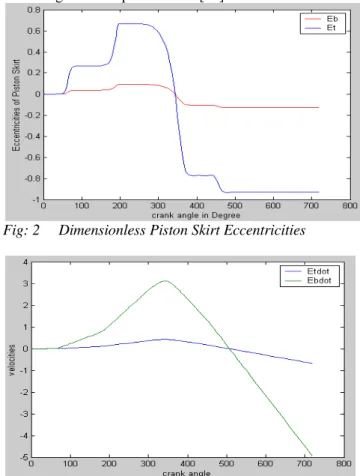
Figure 2 shows dimensionless eccentricities (Et &Eb) and
crank angle. There are three horizontal lines; the lower line is the touching line on the major thrust side, the upper line is the touching line on the minor thrust side and the mid-line (zero line) indicates piston eccentricity to be zero. Et(t) is
the eccentricity of the piston skirt at the top position and Eb(t) is the eccentricity of the piston skirt at the bottom. If
the eccentricity curve goes beyond either the upper line or the lower line then solid-to-solid contact establishes. In our case, where we have assumed the model to be in hydrodynamic regime in the initial engine start up, it can be seen that ‘Et ‘ curve goes close to the lower line during the
piston expansion stroke but it does not touch the line. The Et
& Eb profile curves do not touch either upper or lower line
in the complete 720 degree crank rotation, hence no solid-to-solid contact. This is the improved piston eccentricities profile as compared to Newtonian lubricant when modeling initial engine start up conditions [23].
Fig: 2 Dimensionless Piston Skirt Eccentricities
Fig: 3 Piston Skirt top & Bottom Velocities
B. Effect of Minimum Film Thickness
Time based maximum & minimum lubricant film thickness established between opposing surfaces of piston
skirts and cylinder wall is determined as shown in figure 4.The intake stroke has negligible film thickness. This time period becomes very critical. This corresponds to the piston eccentricities towards minor thrust side. In the compression stroke, oil film thickness rises and attains its vertex near the end of that stroke of piston. This means that more film thickness value increases, more are the chances that piston eccentricities will get reduced. Hence, even lesser chances for any solid-to-solid contacts to take place. In the piston expansion stroke, maximum value of combustion gas force due to ignition (firing) is at 372 degree crank rotation. There is corresponding drop in the values of maximum and minimum film thickness. These values reach the minimum at the end of expansion stroke, which means that by that time full impact of combustion gas force on hydrodynamic pressures as well as film thickness has fully materialized. In the exhaust stroke, oil film thickness starts increasing again until it attains significantly high values at the end of exhaust stroke which corresponds to the 720 degree crank angle.
Fig: 4 Maximum & Minimum Film Profiles
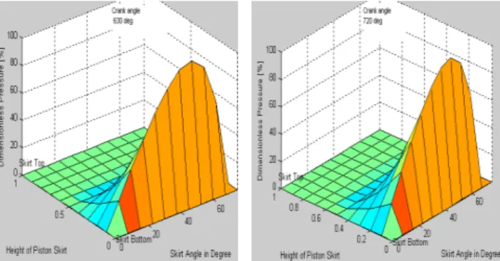
C. Effects of Viscoelasticity on Pressure
Hydrodynamic pressure distribution after incorporating viscoelastic effects is uniform through the entire crank rotation angles, which indicates perfectly aligned piston skirts model, maintaining desirable clearances throughout the entire cycle. It is possible to generate instantaneous 3-D pressure profiles on the skirt surface plane corresponding to all 720o of crank rotation. In our analysis we generated eight such pressure fields each for every 90o crank rotation to evaluate changes in pressure profiles in the entire cycle. For our basic model, results of eight pressure fields at engine start up speed of 600 rpm are shown and discussed below.
angle, piston is at the mid of intake stroke, positive hydrodynamic pressures rise from mid point to the skirt top surface but the slope is gentle and peak pressure value is witnessed at almost centre point of skirt top surface (Refer to Fig:5a). At 180o crank angle, when piston is at the end of intake stroke, positive hydrodynamic pressures rise from mid point to the skirt top surface but the slope gets steep and peak pressure values are seen to shift away from centre point of skirt top surface and towards right side (Refer to Fig:5b).
Fig: 5c Crank angle 270 0 Fig: 5d Crank angle 3600 In the compression stroke, the peak hydrodynamic pressures initially generate at the piston skirt top surface but later shift towards skirt bottom surface showing less gentle slope of instantaneous pressure fields. At 270o crank angle when piston is at the mid of compression stroke, positive hydrodynamic pressures rise from mid point to the skirt top surface but the slope remains steep and peak pressure value is found at the mid of centre and right corner of skirt top surface (Refer to Fig:5c). At 360o crank angle when piston is at the end of compression stroke, there is clear shift of positive hydrodynamic pressures to the skirt bottom surface such that these rise from mid point to the skirt bottom surface. The slope is steep but higher peak pressure values are close to the centre point of skirt bottom surface (Refer to Fig: 5d).
Fig: 5e Crank angle 4500 Fig: 5f Crank angle 5400
In the power stroke, the peak hydrodynamic pressures are generated at the piston skirt bottom surface throughout the entire length of stroke showing less gentle slopes of instantaneous pressure fields. At 450o crank angle when piston is at the mid of power (expansion) stroke, positive hydrodynamic pressures rise from mid point to the skirt bottom surface but the slope gets gentle and higher peak pressure values are found close to the centre point of skirt bottom surface (Refer to Fig:5e). At 540o crank angle when piston is at the end of power/expansion stroke, positive hydrodynamic pressures profiles at the skirt bottom surface have their slope gets gentler but higher peak pressure values again shift from the centre point towards the right of skirt bottom surface (Refer to Fig:5f).
Fig: 5g Crank angle 6300 Fig: 5h Crank angle 7200 In the exhaust stroke, the peak hydrodynamic pressures are generated at the piston skirt bottom surface throughout the entire length of stroke showing gentle slopes of reduced instantaneous peak pressures. At 630o crank angle when piston is at the mid of exhaust stroke, positive hydrodynamic pressures rise from midpoint of skirt to the skirt bottom surface but the slope becomes gentle, peak pressure values are found to have reduced values and shift close to the centre point of skirt bottom surface (Refer to Fig:5g). At 720o crank angle when piston reaches at the end of exhaust stroke, positive hydrodynamic pressure profiles at the skirt bottom surface maintain their gentle slope but at visibly reduced peak pressure values, which again shift slightly from the centre point towards the right of skirt bottom surface (Refer to Fig:5h).
In our case, it is the maximum hydrodynamic pressures that are generated near the top portion of piston skirt during the intake stroke and up to the mid of compression stroke of piston motion with the assumption of flooded regime. In reality, it is the boundary or thin film followed by partial (mixed) lubrication that actually takes place during the first 1-2 minutes of engine start up. This means that the hydrodynamic pressures are replaced by Hertzian pressures at possible solid-to-solid contacts. If this occurs then the piston skirt surface near the top is likely to get damaged. Significant shift of hydrodynamic pressure fields with higher values of peak pressures generating over the skirt bottom surface and simultaneous increased piston eccentricities result as combustion gas force acts over the piston crown and its impact travels down through the skirt. All this means that in reality there are more chances of damage to the skirt bottom surface, if starvation of piston skirt occurs during this period. Here, the role of viscoelastic non-Newtonian engine lubricant assists decreased piston eccentricities and reduces the chances of piston skirt surface establishing any physical contact with cylinder liner surface and subsequent adhesive wear.
IV.CONCLUSIONS
profiles and clearly reduced piston eccentricities under engine start up conditions. It is a very significant finding as the reduced eccentricities may proportionally reduce magnitude of piston skirt wear at engine start up accordingly. Furthermore, we have found that the effect of viscoelasticity on the pressure is dominated by minimum film thickness. Numerical simulations indicate that there is a significant enhancement of the viscoelastic pressure when the minimum film thickness is sufficiently small.
In conclusion, we have addressed and assessed the effects of viscoelasticity on piston lubrication during engine startup conditions. Further extensive work is needed to explore other non-Newtonian fluid-flow aspects related to the lubrication of piston skirts under specified engine operating conditions.
Nomenclature
C = Piston radial clearance = 0.00001m D = 2R = Diameter of Piston = 83.00 mm F = Normal force acting on piston skirts Ff = Friction force acting on skirt surface
FG = Gas force
FIC = Inertia force due to piston mass
FIP = Inertia force due to piston pin mass
h = Film thickness hd = Deborah film thickness
hm = Mean film thickness
Ipis = Piston inertia about its centre of mass
L = Piston skirt length = 33.8mm l = Connecting rod length = 133 mm M = Moment acting on piston skirts Mf = Friction moment acting on skirt surface
mpis = Mass of piston = 0.295 kg mpin = Mass of piston pin = 0.09 kg Ph = Hydrodynamic pressure
r = Crank radius
E ,E Young’s Moduli GPa
µ = Lubricant viscosity = 0.016 Pa.s = Engine speed = 600 rpm τ = Shear stress
η = Kinematic viscosity υ = Poisson’s ratio = 0.3 Φ = Connecting rod angle φ = Crank angle
REFERENCES
[1] Rong Zhang and Xin Kai Li, “Non Newtonian Effects on Lubricant Thin Film Flows,” [J].Journal of Engineering Mathematics
(2005)51:1-13.
[2] Waseem Akhtar, Corina Fetecau , Victor.Tigoiu And Constantin .Fetecau, “Flow Of Maxwell Fluid Between Two Side Walls Induced by A Constantly Accelerating Plate,” Z.Angew .Math. Phys. 60 (2009) 498-510.
[3] Corina Fetecau, D. Vieru, A. Mahmood, C. Fetecau, “On The Energetic Balance for The Flow of A Maxwell Fluid due to A Constantly Accelerating Plate,” Acta Mech 203, 89-96(2009). [4] A. Berker, M. G. Bouldin, S. J. Kleis, W. E. Vanarsdale, “Effect of
Polymer on Flow in Journal Bearing,” Journal of Non-Newtonian Fluid Mechanics, 0377-0257/95.
[5] G. W. Roberts and K. Walters, “On The Viscoelastic Effects In Journal Bearing Lubrication’” Rheologica Acta, Rheol Acta 31:55-62 (1992).
[6] R. P. Chabra, J. F. Richardson, (Book) Non-Newtonian Flow in The Process Industries- Fundamentals and Engineering Application, 2000, pp. 21-83.
[7] Sara J .Hupp, “Defining The Role of Elastic Lubricants and Micro Textured Surfaces In Lubricated, Sliding Friction’” PhD Thesis , Massachusetts Institute of Technology, Feb 2008.
[8] Ilya I. Kudish, Rubber G. Airapetyan and Michael J. Covitch, “Modeling of Lubricant Degradation And Elastohydrodynamic Lubrication,” IUTAM Symposium on Elastohydrodynamics and Micro Elastohydrodynamics, 149-1, 2006, Springer.
[9] Punit Kumar, S. C. Jain, S. Ray, “Influence of Polymeric Fluid Additives in EHL Sliding Line Contacts,” Tribology International
41(2008) 482-492. [10] Ming-Tang Ma, “An Expedient Approach to the Non-Newtonian
Thermal EHL in Heavily Loaded Point Contacts,” Wear 206 (1997) 100-112.
[11] Hong Yiping , Chen Darong, Kong Xianmei, Wang Jiadao, “Model of Fluid Structure Interaction and Its Application to Elastohydrodynamic Lubrication,” Computer Methods Application in Mechanical Engineering, 191.(2002). 4231-4240. [12] J. Seabra, A. Sottomayor , A. Compos, “Non-Newtonian EHL
Model for Traction Evaluation in a Roller-Inner Ring Contact in A Roller Bearing,” Wear,195(1996)53-65.
[13] Hsiao-Ming Chu, Wang-Long Li, Yuh-Ping Chang, “Thin Film Elastohydrodynamic Lubrication - A Power Law Fluid Model,”
Tribology International, 39 2006) 1474-1481.
[14] P. C. Sui, F. Sadeghi, “Non Newtonian Thermal Elastohydrodynamic Lubrication,” Transactions of the ASME, 390, Vol.113 , April 1991. [15] Peiran Yang, Shizhu Wen, “The Behavior of Non Newtonian Thermal EHL Film in Line Contacts at Dynamic Loads. Journal of Tribology, January 1992, Vol. 114/81.
[16] Punit Kumar, M. M. Khonsari, Scott Bair, “Full EHL Simulation Using the Actual Ree-Eyring Model for Shear Thinning Lubricants,”
Journal of Tribology, January 2009, Vol. 131/011802-1
[17] J. P. Charmleffel, G. Dalmaz, P.Vergne, “Experimental Results and Analytical Film Thickness Predictions in EHD Rolling Point Contacts,” Tribology International, 40 (2007) 1543-1552.
[18] J. G. Wang and J. J. Ma, “On the Shear Stress of Elastohydrodynamic Lubrication in Elliptical Contacts,” Tribology International, Vol. 29. 0301-679x(96)0005-9.
[19] R. C. Bhattacharjee and N. C. Das, “Power Law Fluid Model Incorporated into Elastohydrodynamic Lubrication Theory of Line Contact,” Tribology International, Vol. 29, 0301-679x(95) 00096-8. [20] Dong Zhu, Herbert S. Cheng, Takayuki Arai, Kgugo Hamai, “A
Numerical Analysis for Piston Skirts in Mixed Lubrication,” ASME. 91-Trib-66.
[21] J-R Lin, M-Y. Teng and M-H. Ho, “Effects of Non Newtonian Rheology on the Film Height History Between Non Parallel Sliding- Sequeezing Surfaces. Journal of Engineering Tribology, Vol 221. Doi: 10.1243/13506501 Jet 158
[22] Gwidon W. Stachowiak and Andrew W. Batchelor, (Book)
Engineering Tribology, Third Edition, pp. 112-219