Bogdanovi}, B. P., et al.: Low-Pressure Reversible Axial Fan Designed with …
THERMAL SCIENCE, Year 2012, Vol. 16, Suppl. 2, pp. S605-S615 S605
LOW-PRESSURE REVERSIBLE AXIAL FAN DESIGNED WITH
DIFFERENT SPECIFIC WORK OF ELEMENTARY STAGES
by
Božidar P. BOGDANOVI], @ivan T. SPASI]*, and Jasmina B. BOGDANOVI]-JOVANOVI]
Faculty of Mechanical Engineering, University of Niš, Niš, Serbia
Original scientific paper DOI: 10.2298/TSCI120503195B
Low-pressure axial fan impellers designed according to the principle of equal specific work of all elementary stages have blades whose profile near the fan hub is under a significantly larger inclination angle than at the impeller periphery. In order to minimize the spatial curvature of the fan blades and the fan hub length, impeller blades of low-pressure axial fans can be designed with different specific work of elementary stages, so that the specific work of elementary stages is smaller at the hub than at the periphery. This paper presents the operating char-acteristics of a low-pressure reversible axial fan with straight blade profiles, de-signed with different specific work of elementary stages. The fan was tested on a standard test rig, with air intake loading on the suction side of the fan.
Key words: reversible axial fan, elementary stages, blade, characteristics, experiment
Introduction
The basic assumption in the design of axial turbomachinery is that its flow surfaces are axisymmetric. For the flow surfaces to be cylindrical or nearly cylindrical, axial fans are usually designed according to the principleof equal specific work of elementary stages. In or-der to minimize the spatial curvature of the fan blades and the fan hub length, impeller blades of low-pressure axial fans can be designed with different specific work of elementary stages, so that the specific work of elementary stages is smaller at the hub than at the periphery. For determining the shape of the fan blades it is sufficient to define their profile in 5 to 12 elemen-tary stages, approximately evenly distributed over the height of the blades.
Calculating the fan with different specific work of elementary stages
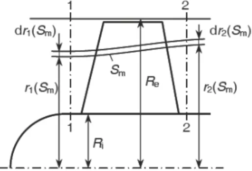
Figure 1 shows a schematic of a meridian section of a fan impeller, with traces of two elementary immediate axisymmetrical flow surfaces, where one (below) is marked as Sm. A flow space between two elementary immediate axisymmetrical flow surfaces represents an
––––––––––––––
* Corresponding author; e-mail: [email protected] po širini i po
Č
Č
Č
Č
elementary stage of the fan runner, and an inter-section of axisymmetrical flow surface Sm and fan blades defines the blade profile cascade of the elementary stage.
Control cross-sections in front of (1) and behind (2) the fan impeller are placed far enough from the blade runner, therefore, it can be assumed that flow parameters of the cross-sections do not depend on the circumferential co-ordinate ().
For low-pressure axial flow fans that are de-signed with a fan runner only, the following can be written: ptot1= const. and cu1= 0.
According to the Euler’s equations for tu r-bomachinery, the specific work of elementary stage of the fan impeller is:
2
k( m)
2( m) u ( m), for u10y S r S c S c (1)
and the total pressure increase in the elementary stage:
2 1 2 1
tot m tot m tot m tot 2 m tot
Δ ( )p S p ( )S p ( )S p r S( ) p (2)
or
tot m h m k m
Δp ( )S ( )S y S( ) (3)
where h(Sm) is the hydraulic efficiency of elementary stage if the fan impeller:
g m tot m
h m
k m k m
Δ ( ) Δ ( )
( ) 1
( ) ( )
p S y S
S
y S y S (4)
where yg(Sm) is the mechanical loss of flow energy in the elementary stage of the fan impel-ler.
It is assumed that the hydraulic efficiency is equal for all elementary stages.
If Q[r(Sm)] is the flow rate of the gas flowing through the flow space between the fan hub and the axisymmetrical flow surface Sm, according to the continuity law (for 1 = 2 = = = const.), follows:
1 m 2 m1 2
i i
m
( ) 2
( ) d 2
( ) dr S r S
z z
R R
Q r S c r r r c r r r (5)
where cz1 and cz2 are the distribution functions of axial component of flow velocity in control cross-sections in front of and behind the fan impeller, which have to fulfill the requirement:
e e
1 2
i i
2 ( ) d 2 ( ) d
R R
z z
R R
Q c r r r c r r r (6)
For the known function yk(r), the specific work of the fan impeller can be calculated using the equation:
e
2
2 i
k k k
1 1
( ) d 2 ( ) ( ) d
R
zA R
Y y r Q y r c r r r
Q Q (7)
The necessary condition is that control cross-sections are placed in the space which is physically bounded by the cylindrical surface of the fan hub (Ri = const.) and the fan shroud (Re = const.).
The equation of steady fluid flow of the inviscous fluid can be written in the form: (for cylindrical flow surfaces the flow does not depend on the circumferential co-ordinate ()).
tot ( ) 1
u u
z z
c rc p c
c
r r r r
(8)
For the fluid flow in front of the fan impeller cu = cu1 = 0 and ptot = ptot1 = const., therefore due to eq. (8), for cz = cz1, follows: cz1/r = 0, tj. i. e. cz1 = const.
The total pressure in the control cross-section 2 of the fan impeller ηh(Sm) = const.,
ptot1 = const. and yk(Sm) = yk(r)2 is:
2 1
tot ( ) tot
h k( )2p r p Y r (9)
and circumferential component of absolute velocity:
2 k 2 2 k 2
1 1
( ) and ( )
u u
rc y r c y r
r (10)
Considering the above equations for obtaining cylindrical surfaces in the control cross-sections behind the fan impeller (for ptot = ptot2; cz = cz2,and cu = cu2), the following is assumed:
2 2
k h 2 2 k
( ) 1 ( )
z zc y r
c y r
r r r
(11)
where
h 2 2 k 1
( ) 0
y r
r
By analyzing this equation, one can conclude:
the flow surfaces in fan impeller are cylindrical, for Yk(r) = const.; yk(r)/r = 0, cz2 = cz1 = const., r2(Sm) = r1(Sm), and
cylindrical flow surfaces in the control cross-sections in front of and behind the fan runner do not remain cylindrical inside the fan impeller: yk(r)/r 0, cz2/r 0,
r2(Sm) > r1(Sm).
Distribution function of specific work of elementary stages
2
k o i o
k k.o o e
( ) 2r , za
( ) const., za
y r A Br Br R r r
y r y r r R (12)
where yk(r)/r = 0, for r = r0.
The function yk(r) is defined according to assumption parameters ro (RiroRe)and
yk.i = yk(Ri), and the recommendation is:
+o i e k.i k
1
and 0,6 0,7 2
r R R y Y (13)
where Yk +
is the calculation of the (nominal) specific work of the fan impeller.
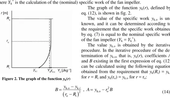
The graph of the function yk(r), defined by eq. (12), is shown in fig. 2.
The value of the specific work yk.o is un-known, and it can be determined according to the requirement that the specific work obtained by eq. (7) is equal to the nominal specific work of the fan impeller (Yk = Yk
+ ).
The value yk.o is obtained by the iterative procedure. In the iterative procedure of the de-termination of yk.o, that is, yk(r), coefficients A and B existing in the first expression of eq. (12) can be calculated using the following equation obtained from the requirement that yk(Ri) = yk.i for r = Ri and yk(ro) = yk.o for r = ro:
k.o
k.2 k.o o2o i , i y y
B A y r B
r R (14)
Assuming that the flow surfaces are cylindrical in the control cross-section behind the fan impeller, the following is obtained:
2
2 2
2
i o
2
z z o e
, za
c const. c (0), za
z c
r R r r
r r r
r r R
(15)
where
o h 2 h 2
2
o o
2 2
3
4 , 4 ,
2 4
4 ,
B B
r B B
A r B r AB B
(16)By integrating the first expression of eq. (15), the following is obtained:
2 2
2 2 2
o
z z o o
o
1 1 1
c ( ) c (0) ( ) ( ) ln
2 r
r r r r r
r r r (17)
The equations used in the iterative procedure of the determination of yk.o and cz2(0), taking into account the form of functions cz2(r) and yk(r), are derived in the following forms:
o
2 i
2 2
z2 e o
2 ( ) d (0)( )
r
z R
Q c r r r c R r (18)
o
2 2
i
2 2
k k k.o e o
1 1
2 ( ) ( ) (0)( )
r
z z
R
Y y r c r rdr y c R r
Q Q (19)
Values yk.o and cz2(0)are determined by the iterative procedure, using the programs [1]. Apart from determining the values yk.oand cz2(0), the program is created in such a way so as to also yield yk(r), cz2(r) and Q(r)in the defined step, where r is the radius in control cross- -section behind the fan impeller and Q(r) is the flow rate under the cylindrical flow surface of the radius r.
According to the data for Q(r), a functional relation of cylindrical axisymmetrical flow surface radius in front of and behind the fan impeller can be established. Due to eq. (5), for Qr(Sm) = Q(r), r1(Sm) = r1(r), and cz1 = const. = czsr, the following is obtained:
2
1 i
sr ( ) ( )
( )
Q r r r R
c z
(20)
According to the relation r/r1(r), a deviation between axisymmetrical and cylindrical flow surfaces can be evaluated.
In references [1-3], fan impeller blades are designed for the asummed value of spe-cific work of elementary stages at the hub yk.i (yk.i = 0,6Yk
+
) and different values of radius r0 where one can observe the change in the spatial curvature of the fan blades L = t = ti –te and profile cascade width for elementary stages, especially at the fan hub (bi) which defines the minimum lenght of the hub.
Calculation of the model fan
For calculation parameters: Q+ = 3.61 m3/s, Δptot +
= 180 Pa, n = 1405 rpm (YK+ = = 200 J/kg, czsr = 15.73 m/s) for assumed efficiency (hydraulic h= 0.75 and total = 0.65), according to the model with constant specific work of elementary stages, a fan with the ge-ometry of the impeller was designed [2-4]:
Ri = 0.150 m – radius of the fan impeller hub,
Re = 0.315 m – peripheral radius of the fan impeller, and
zK = 6 – number of impeller blades.
For the given calculation parameters and with equal blade profile lengths l for ele-mentary stages i (tab. 1), the calculation of the axial fan impeller with different specific work of elementary stages was performed. The calculation was performed according to the model where specific work of elementary stages changed along the entire height of the blade (ro = Re) as in the extreme case [1].
For ro = Re= 0,315 m and yK.i = 0,6YK = 120 J/kg the function of the change of spe-cific work along radius r is obtained:
2 k
and the function of the change of velocity:
2
z
2 2
0,315 1
c ( ) 692ln 37,8 3,175
16,82 6453(0,315 ) 7360(0, 0992 )
r
r
r A
r r
A r r
(22)
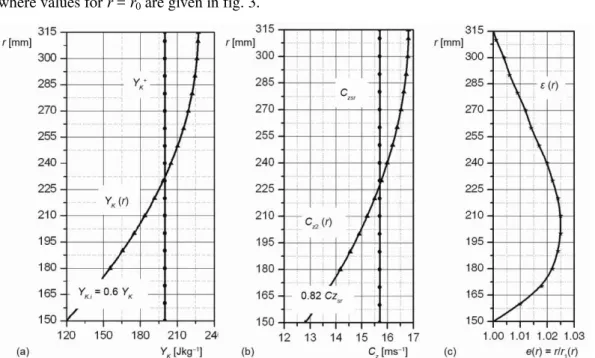
where values for r = r0 are given in fig. 3.
Figure 3. Graphs of the functions; (a) yK (r), (b) cz2(r), and (c) ε(r)
For calculation operating parameters, according to which the graphs of the functions of specific work yk(r), fig. 3(a), and meridian component of absolute velocity cz2(r), fig. 3(b), were determined, a low-pressure reversible axial fan with straight blade profiles was
con-structed. Maximum deviation between axisymmetrical and cylindrical flow sur-faces was 2.6%, fig. 3(c), therefore the calculation was performed using the model of cylindrical flow surfaces and taking into account the velocity distribu-tion cz2(r) and using the method of lift forces. The results of the calculations [2] are given in tab. 1.
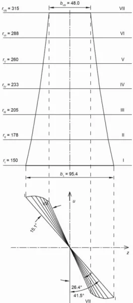
The difference in the inclination angles of the profile mean line at the hub (ti = 41.5°) and the shroud (te = 26.4°), the angular spatial blade curvature L (tab. 1 and fig. 3), is L. = t = ti. –te. = 41.5– 26.4 = 15.1°, with the profile cascade width of bi = 95.4 mm.
The fan impeller blade designed according to the unequal distribution of specific work of the elementary stages (fig. 4), has a smaller spatial curvature than the fan blade constructed Table 1. Results of the calculations
Section
i
ri
[mm]
ti
[mm]
li
[mm]
t i /l i
[–]
ti
according to the equal distribution of specific work of all elementary stages by 14° [2, 3]. The inclination angles of the profile mean line at the hub are smaller, that is, a smaller profile cascade width at the hub by 21 mm (22%) which requires the smaller length of the hub impeller [2].
Manufacture of the model for experimental testing
Based on the calculation of the fan, for seven equally distributed elementary stages along the height of the impeller blade (tab. 1), a blade with straight profiles was designed (PP2 profiles) [2]. On the basis of the defined profiles for seven elementary stages, a 3-D blade was designed in the SolidWorks program, which could serve as a model to obtain the geometry of the blade profile for any cylindrical section along the height of the blade. This fact was used in the manufacturing of the blade model from segments.
The blade model (fig. 5) was manufactured from thin stacked and glued straight profile wooden segments (26 segments), whose draw-ings were prepared and done in SolidWorks. After gluing the segments together, the surface of the blades was planed.
To determine the accurate geometry of the blade model, scanning was performed on a 3-D scanner type MDX-20 (fig. 6), with the scan-ning step of 0.05 mm in the direction of axes x and y, and in the direction of axis z with the step of 0.025 mm.
Following the spatial scanning of the blade, the 3-D geometry of the blade was obtained, and it was possible to create cylindrical sections
of the blade in SolidWorks, so as to obtain the geometry and inclination of blade profiles (2-D) in cylindrical sections (tab. 2). Figure 7 shows the profile mean lines of the scanned blade developed in a plane.
The scanned model of the fan blade has a spatial curvature which is defined as a dif-ference between the inclination angles at the hub and the shroud, L = t = ti–te = 12° (fig. 7). The model has a smaller spatial curvature in relation to the designed blade by 3.1°, which is explained by the error in the described technology for model manufacturing.
The scanned model of the blade with a straight profile has a smaller spatial curva-ture than the model of the blade designed with equal specific work of elementary stages (L = t = ti–te = 29.1°) by 17.1°[2].
(a) (b)
Figure 5. Blade model manufactured from wooden segments; (a) before painting, (b) after painting
Figure 6. Scanning the model blade on the MDX-20 scanner
Table 2. Dimensions of the scanned blade
Section i ri [mm] hi [mm] hi/h [–] li [mm] βti [°] δmaxi [mm] r1,2 [mm] (δmax/l)i [–]
I 150 0 0.0000 144.0 12 12.0 2.40 0.08
II 160 10 0.0606 141.6 9.6 11.6 2.32 0.08
III 170 20 0.1212 139.1 7.5 11.3 2.26 0.08
IV 180 30 0.1818 137.6 6.5 10.9 2.18 0.08
V 190 40 0.2424 135.6 5.0 10.5 2.10 0.08
VI 200 50 0.3030 132.7 4.3 10.2 2.04 0.08
VII 210 60 0.3636 130.7 3.8 9.8 1.96 0.07
VIII 220 70 0.4242 128.7 3.2 9.5 1.90 0.07
IX 230 80 0.4848 126.2 2.9 9.1 1.82 0.07
X 240 90 0.5455 123.8 2.6 8.7 1.74 0.07
XI 250 100 0.6061 121.3 2.1 8.4 1.68 0.07
XII 270 120 0.7273 117.3 1.5 7.6 1.52 0.06 XIII 290 140 0.8485 113.9 1.0 6.9 1.38 0.06 XIV 310 160 0.9697 109.9 0.6 6.3 1.26 0.06
XV 315 165 1.0000 107.9 0 6.2 1.24 0.06
Table 2 key: i– cylindrical section, ri– radius, hi – height of the blade up to the cylindrical section, hi/h– relative height of
the blade, li – the length of the blade profile mean line, βti– difference between the profile mean line inclination angles in
the specific cylindrical section and the peripheral section, δmaxi– maximum thickness of blade profile, r1,2 – radii of the rounding of the blade profile end, δmaxi/li– relative maximum thickness of the blade profile
Experimental testing
The testing and obtaining of the operating characteristics of the fan was conducted by air loading on the suction side of the fan, for a nominal rotation speed of the electric motor
n = 1405 rpm [5, 6]. The diameter of the fan shroud was De' = 635 mm, the periphery diame-ter of the impeller was De = 630 mm and the diameter of the impeller hub was Di= 300 mm.
The testing was conducted on a standard test rig (AMCA 210), with the suction duct with the diameter D = 690 mm (fig. 8), in the Laboratory for Hydraulic and Pneumatic Test-ing of the Faculty of Mechanical EngineerTest-ing in Nis. Apart from measurTest-ing the pressure and determining the flow, the electrical magnitudes at the entry into the electric motor of the fan, and the rotation speed of the fan and air parameters in the laboratory (atmospheric pressure and temperature) were also measured. The power of the electric motor was PM= 1.5 kW, the characteristics of which were known [2].
Figure 8. Test rig for testing axial flow fans
1 – Fan for testing, 2 – Deflector, 3 – Prandtl probe with traverse, 4 – Channel testing, 5 – Airflow
straightener, 6 – Stand, I-I– Cross-section for measuring flow rate, I-I – Cross-section in front of the fan, II-II – Cross-section behind the fan
The volume flow rate was determined on the basis of the measured and mean pres-sure rate in the cross section I-I. The dynamic pressure was measured with the Prandtl probe in five points that were deployed on the defined radii [2, 6]. The total rise in the pressure in the fan was determined as the difference of total pressures behind (pIItot) and in front of the fan (pItot):
tot IItot Itot
p p p
(23)
For testing the fan for suction and free airflow outlet into the atmosphere (fig. 8), the total rise in the pressure in the fan equaled the static pressure (vacuum) in the cross-section in front of the fan [4]:
(V) tot I p p
(24)
Static pressure in front of the fan was measured in the cross section I-I, using a pie-zometer ring, while static pressure behind the fan (cross section II-II) was considered as equal to the atmospheric pressure.
Results of the experimental testing
cylin-drical shape of the hub, was filled with silicone. For the region of the stable performance of the fan, the diagrams of operating characteristics of the fan are shown, total pressure rise ptot(Q), power P(Q) and efficiency (Q), obtained on the testing stand for various impeller blades angle (L). The fan characteristics were calculated for a constant rotation speed of the fan n = 1405 rpm and air density = 1.2 kg/m3.
Figure 9. Total pressure rise of the fan, ptot(Q) Figure 10. Power and efficiency characteristics, P(Q) and (Q)
The analysis of the obtained results: calculation parameters (ptot = 180 Pa, Q = 3.61 m3/s = 13000 m3/h), for the nominal rotation speed of the electric motor (n = 1405 rpm) were achieved for the impeller blade angle of L = 41.5°, with relatively high efficiency = 0.64.
In optimal operating regime ( = max), the fan achieved a maximum efficiency of
= 0.64 (ptot = 185 Pa, Q = 12000 m3/h ) for the impeller blade angle of L= 40°. With the increase of the blade angle, the fan flow and total pressure rise increase too, but the values of efficiency decreased. For the impeller blade angle L= 50° (ptot = 235 Pa, Q = 16200 m3/h ), the efficiency was = 0.59.
Conclusions
The reversible axial fan with straight blade profiles designed according to the model with different specific work of elementary stages has the angular spatial curvature smaller by 17.1° and the width of the blade profile cascade at the hub smaller by 20.6 mm (22%), which requires a smaller length of the impeller hub in relation to the blades designed according to the model with the constant specific work of elementary stages [2].
The blades of the fan impeller designed according to the model of unequal specific work of elementary stages, due to the smaller width of the profile cascade at the hub, require a smaller length of the hub, are easier to manufacture, and have slightly lower efficiency than the blades designed with the constant specific work of elementary stages [2].
On the basis of the conducted testing, it is suggested that the design of low-pressure reversible axial fans be performed according to the model with unequal specific work of ele-mentary stages.
Nomenclature
cz – axial velocity component, [ms1]
l – profile length, [m]
n – rotation speed, [rpm]
P – power, [W]
p – pressure, [Pa]
Q – flow rate of the fan, [m3s1]
r – radius, [m]
t – pitch, [m]
YK – specific work of the impeller, [Jkg1]
yk(r) – specific work of elem. stage, [Jkg1]
Greek symbols
L – impeller blade angle, [°]
t – angle inclination of the profile mean line,
[°]
δ – thickness profile, [m]
L – spatial curvature of the blade, [°]
– efficiency, [–]
– density, [kgm–3]
Subscripts
1, 2 – inlet and outlet t – mean line e – periphery
i – for hub, cylindrical sections h – hydraulic
k – impeller
References
[1] Bogdanović, B., Bogdanović-Jovanović, J., Spasić, Ž., Designing of Low Pressure Axial Flow Fans with Different Specific Work of Elementary Stages,Proceedings on CD, The international conference Mechanical Engineering in XXI Century, 2011, Faculty of Mechanical Engineering, University of Nis, Nis, Serbia, pp. 99-102
[2] Spasić, Ž., Numerical and Experimental Investigation of the Influence of the Blade Profile Shape on the Reversible Axial Fan Characteristics (in Serbian), Ph. D. thesis, Faculty of Mechanical Engineering, University of Nis, Nis, Serbia, 2012
[3] Bogdanović, B., et al., The Development Construction of Reversible Axial Fans (in Serbian), Report for project No. 18012, funded by the Serbian Ministry of Education, Science and Technological Develop-ment, the period: 31.04.2008-31.04.2011
[4] Еck, B.,Fans-Design and Operation of Centrifugal, Axial-Flow and Cross-Flow Fans, Pergamont Press, Oxford, England, 1973
[5] Spasić, Ž., Bogdanović, B., Radić, M., Variation of Operation of Low-Pressure Reversible Axial Fans Driven by Induction Motor from Start to the Steady-State, Proceedings on CD, SIMTERM 2011, Soko-banja, 2011, pp. 586-595
[6] Bogdanović, B., Milenković, D., Bogdanović-Jovanović, J., Fans-Performance and Operating Charac-teristics (in Serbian), Faculty of Mechanical Engineering, University of Nis, Nis, Serbia, 2012