Universidade De Aveiro Departamento Electrónica, Telecomunicações e
Informática 2014
Bruna Patrícia
Contextos de Convergência em Redes de Acesso
Rodrigues
de Nova Geração
Paredes
Contexts Requirements
in New Generation Access Networks
Universidade De Aveiro Departamento Electrónica, Telecomunicações e
Informática
2014
Integrated Master Degree in Telecommunication and Electronics Engineering
2014
Bruna Patrícia
Contextos de Convergência em Redes de Acesso
Rodrigues
de Nova Geração
Paredes
Contexts Requirements
in New Generation Access Networks
Dissertation presented to the University of Aveiro for fulfillment of the necessary requirements to the attainment of the degree of Master in Electronic and Telecommunication Engineering, accomplished under the scientific orientation of Prof. Dr. António Teixeira and Prof. Dr. Mario Lima, both of the Department of Electronic, Telecommunications and Informatics (DETI) and of the Institute of Telecommunication (IT) of Aveiro’s University.
Universidade De Aveiro Departamento Electrónica, Telecomunicações e
Informática
2014
I want to dedicate this work to my family, in particular to my parents and sister who had supported me tireless and unconditionally. Also to my dated one, for all the patience, all the strength and for never let me to give up. I also dedicate to my truly friends, especially to Susana Bento and Sir Master Engineer Simão Brandão, who had always believed me and had directed me in the right way.
Universidade De Aveiro Departamento Electrónica, Telecomunicações e
Informática
Universidade De Aveiro Departamento Electrónica, Telecomunicações e
Informática
2014
The Jury
President Professor Doctor José Carlos da Silva Neves
Cathedratic Professor of University of Aveiro
Examiners Committee Professor Doctor Paulo Sérgio de Brito André
Associated Professor with aggregation from University of Lisbon
Professor Doctor Mário José Neves de Lima
Universidade De Aveiro Departamento Electrónica, Telecomunicações e
Informática
Universidade De Aveiro Departamento Electrónica, Telecomunicações e
Informática
2014
Gratefulness These past years at university, kind were the best years I had. I met new people, had new experiences, grew up and got matured. I became a new person with new feelings and new perspectives of life. Now it is time to take another step forward and I will never forget everyone who helped me at this stage.
First of all, I want to give a deep thanks to my parents and my sister for all the support and for believing in me throughout my academic career. I love them and I’m proud of them every day.
To my boyfriend for being by my side every day and for every night, before going to sleep, encourage me to wake up the next day and give my best. He is my truly better half.
To Susana Bento, my truly friend, for being with me all these years of study and for always believe in my capacities and myself.
To my friends that help me to be the person I am today, for every laugh and every push to the right way. Mainly, thank you Sir Master Engineer Simão Brandão, Sir Master Engineer Ricardo Ferreira, Sir Master Engineer Diogo Viana and Sir Master Engineer Francisco Arrabaça. To Aveiro’s University, as my mainly instruction institution, and Telecommunication’s Institute for all the material and good conditions of establishment provided.
To Mr. Ali Shaphari, an extraordinary and tireless person, I want to give a special thankful for all the help and every hour spent with me in the laboratory. Without him, this would not be possible.
Finally, a special thankful to my professors, Prof. António Teixeira and Prof. Mário Lima, for all the good given orientation and indicated paths.
Universidade De Aveiro Departamento Electrónica, Telecomunicações e
Informática
Universidade De Aveiro Departamento Electrónica, Telecomunicações e
Informática 2014
“The only limit to our realization of tomorrow will be our doubts of today. Let us move forward with strong and active faith.”
Universidade De Aveiro Departamento Electrónica, Telecomunicações e
Informática
Universidade De Aveiro Departamento Electrónica, Telecomunicações e
Informática
2014
Keywords Passive Optical Networks, G-PON, XG-PON, NG-PON2, Raman, TWDM-PON, Advanced Modulation Formats, QPSK, 16QAM
Abstract The Internet is increasingly becoming part of everyday life. Once the traffic demands are growing much more rapidly than the available revenue, it is visible the gradual increase of the need for broadband services. In recent years, telecom operators have shown a great interest in providing various services to residential customers, using the Passive Optical Network (PON) topology. This strong investment has led to several standards in order to achieve the potential subscribers and nowadays is being developed the next generation. The future goal is clear - NGPON2 must overcome previous technologies in ODN compatibility, capacity, bandwidth and cost-efficiency. After several studies, in April 2012, FSAN (Full Service Access Network) defined TWDM (Time-Wavelength Division Multiplexing) as the more attractive solution to fulfill the necessary requirements. On March 2013, was approved the ITU-T G.989.1 recommendation addressing possible wavelength plans, according operator’s needs. The most important requirement for this new access generation is to provide an environment of coexistence with the legacy PON and others. In this order, it is necessary new allocation in the spectrum and further interference studies, to preserve all the systems intact.
In this scope, the following document presents a study over
the new technology TWDM separately, including general features and limitations. Both simulated and experimental results were obtained. Afterward, it is introduced within several coexistence scenarios, with the legacy and signals with different modulation formats, to observe the effect created on its performance. Were taken into account some parameters as channel spacing, transmitted power and high bit rates. The aim is to create a heterogeneous network with high data rate formats coexisting in the same access network to study and help defining the next generation max occupancy of a given network.
Universidade De Aveiro Departamento Electrónica, Telecomunicações e
Informática
2014
Palavras-Chave Redes Ópticas Passivas, G-PON, XG-PON, NG-PON2, Raman, TWDM-PON, Formatos Modulação Avançada, QPSK, 16QAM
Resumo A Internet está a ter um papel cada vez mais activo no quotidiano
actual. As exigências de tráfego estão a aumentar
consideravelmente mais do que a receita disponivel, sendo que se torna visível a extrema necessidade por servicos de banda larga.
Recentemente, os operadores de telecomunicações tem
demonstrado um vasto interesse em providenciar serviços a clientes residenciais, usando Redes Ópticas Passivas (PON). Este forte investimento levou ao desenvolvimento de vários standards, estando actualmente a ser desenvolvida a nova geracão da rede. O novo objectivo é bastante claro – NGPON2 deve superar as tecnologias anterioes relativamente à compatibilidade ODN, capacidade, largura de banda e custo-eficiência. Após vários estudos, em Abril de 2012, FSAN ((Full Service Access Network) definiu TWDM (Time-Wavelength Division Multiplexing) como sendo a solução mais atractiva para preencher os requisitos necessários. Em Março de 2013, foi aprovada a norma ITU-T G.989.1 endereçando novos planos de comprimentos de onda, de acordo com as exigências dos operadores. O requisito mais importante para esta nova rede de acesso centra-se em garantir uma possível co-existência com as redes PON já desenvolvidas. Para esse efeito, torna-se essencial uma nova alocação de espectro e posteriores estudos de interferência, garantindo, assim, a preservação de todos os sistemas.
No âmbito do referido acima, o presente documento expôe
inicialmente um estudo acerca da nova tecnologia TWDM, incluindo caracteristicas gerais e suas limitações. Foram obtidos, para tal, resultados experimentais e simulados. Posteriormente, é efectuado um estudo da tecnologia TWDM em co-existência com redes PONs anteriores e, também, com sinais modulados com diferente formatos. Estes cenários tem o propósito de observar os efeitos gerados no seu desempenho. Alguns parâmetros, como espaçamento entre canais, potência de transmissão e taxas de transmissão de bits foram tidos em consideração. O objectivo é criar uma única rede heterogénea onde vários formatos de alta transmissão de dados co-existem, por forma a optimizar e definir a máxima ocupação da rede de acesso de nova geração.
Universidade De Aveiro Departamento Electrónica, Telecomunicações e
Informática
2014
Contents
CONTENTS ... I FIGURE’S LIST ... V TABLE’S LIST ... VIII ACRONYMS LIST ... IX 1 INTRODUCTION ... 1 1.1 MOTIVATION ... 1 1.2 GOALS ... 2 1.3 STRUCTURE ... 2 1.4 MAIN CONTRIBUTIONS ... 3 2 STATE OF ART ... 5 2.1 INTRODUCTION ... 52.2 PASSIVE OPTICAL NETWORKS ... 6
2.3 ETHERNET PON (EPON) ... 9
2.3.1 Architecture ... 9 2.3.2 Features ... 10 Bit Rate ... 10 Line Code ... 10 Physical Reach ... 10 Split Ratio ... 10 Wavelength Range ... 11 Error Correction ... 11 2.3.3 Transmission ... 11 Downstream and Upstream Traffic ... 11 Ranging ... 13 Auto Discovery ... 14
2.4 GIGABIT PON (GPON) ... 15
2.4.1 Architecture ... 15 2.4.2 Features ... 17 Bit Rate ... 17 Line Code ... 17 Physical and Logical Reach ... 17 Split Ratio ... 17 Wavelength Range ... 18 Error Correction ... 18 2.4.3 Transmission ... 18 Upstream and Downstream Traffic ... 18 Ranging ... 19 Dynamic Bandwidth Allocation ... 20 Data Encapsulation Method ... 21 2.4.4 Wavelength Coexistence Issues ... 21 2.4.5 Reach extender ... 25
2.5 NEXT GENERATION PON (NGPON) ... 25
2.5.1 Introduction ... 25
2.5.2 Roadmap ... 26
2.6 10 GIGABIT PON (XGPON) ... 27
2.6.1 Architecture ... 27
2.6.2 Features ... 29
Bit Rate ... 29
Split Ratio ... 29 Wavelength Range ... 29 Fiber Reach ... 30 Optical Power Budget ... 30 Error Correction ... 30 2.6.3 System Requirements ... 31 Dynamic Bandwidth Allocation ... 31 2.6.4 Migration Scenarios ... 31 2.6.5 Co-existence issues ... 32
2.7 NEXT GENERATION PON 2 (NGPON2) ... 34
2.7.1 Requirements ... 34 2.7.2 Spectral Options ... 35 2.7.3 Candidate Technologies ... 37 OFDM ... 38 OCDM ... 38 WDM ... 39 40 Gbps TDM ... 39 UDWDM ... 39 TWDM ... 40 2.7.4 TWDM-PON selection ... 41 Architecture ... 41 Features ... 42 Power Budget ... 42 Wavelength Range ... 43 Migration and Co-existence Scenarios ... 44 2.8 MODULATION FORMATS ... 46 2.8.1 NRZ-OOK ... 47 2.8.2 QPSK ... 48 2.8.3 16QAM ... 49 3 SIMULATION RESULTS ... 50
3.1 PON SYSTEM CHARACTERIZATION ... 50
3.1.1 Introduction ... 50 3.1.2 GPON System Characterization ... 50 Optical Spectrum ... 50 System Sensitivity ... 51 Maximum Reach ... 52 3.1.3 XGPON System Characterization ... 53 Optical Spectrum ... 54 System Sensitivity ... 55 Maximum Reach ... 56 3.1.4 TWDM System Characterization ... 57 Optical Spectrum ... 58 System Sensitivity ... 59 Maximum Reach ... 60 3.1.5 Conclusions ... 62 3.2 COEXISTENCE SCENARIOS ... 63 3.2.1 Coexistence GPON, XGPON and TWDM ... 63 VPI Setup ... 64 Results ... 65 Conclusions ... 69 3.2.2 Coexistence TWDM and QPSK signal ... 69 VPI Setup ... 70 Results ... 70 Conclusions ... 72 3.2.3 Coexistence TWDM and 16QAM signal ... 73
Conclusions ... 75 4 LABORATORY RESULTS ... 76 4.1 INTRODUCTION ... 76 4.2 TWDM CHARACTERIZATION ... 76 Setup ... 76 Optical Spectrum ... 77 System Sensitivity ... 77 Conclusions ... 78 4.3 FILTER CHARACTERIZATION ... 79
4.4 COEXISTENCE TWDM AND NRZ SIGNAL ... 80
Setup ... 80
Results ... 80
Conclusions ... 83
4.5 COEXISTENCE TWDM AND QPSK SIGNAL ... 84
Setup ... 84
Results ... 84
Conclusions ... 86
4.6 COEXISTENCE TWDM AND 16QAM SIGNAL ... 87
Setup ... 87 Results ... 88 Conclusions ... 90 5 CONCLUSIONS AND FUTURE WORK ... 91 5.1 CONCLUSIONS ... 91 5.2 FUTURE WORK ... 92 REFERENCES ... 94 APPENDIX A. LINEAR AND NONLINEAR EFFECTS ... 99 A.1. INTRODUCTION ... 99
A.2. LINEAR EFFECTS ... 99
A.2.1. Attenuation ... 99
A.2.2. Chromatic Dispersion ... 100
A.3. NONLINEAR EFFECTS ... 101
A.3.1. SPM (Self-Phase Modulation) ... 101 A.3.2. XPM (Cross-Phase Modulation) ... 102 A.3.3. SRS (Stimulated Raman Scattering) ... 103
Figure’s List
FIGURE 1.1 - BANDWIDTH AVAILABLE TO USERS [1] ... 1
FIGURE 2.1 - WAVELENGTH ALLOCATION PLAN IN ITU-T G.983.3[12] ... 5
FIGURE 2.2 - TYPICAL ARCHITECTURES OF A PON NETWORK [13] ... 6
FIGURE 2.3 – WDM-PON NON-STANDARD PROTOCOL [14] ... 8
FIGURE 2.4 – TDM-PON NON-STANDARD PROTOCOL [16] ... 8
FIGURE 2.5 – EPON ARCHITECTURE [18] ... 10
FIGURE 2.6 - RANGE OF WAVELENGTHS FOR EPON STANDARD [20] ... 11
FIGURE 2.7 – DOWNSTREAM TRAFFIC FLOW IN EPON [21] ... 12
FIGURE 2.8 – DOWNSTREAM FRAME FORMAT EPON [21] ... 12
FIGURE 2.9 – UPSTREAM TRAFFIC FLOW IN EPON [21] ... 12
FIGURE 2.10 – UPSTREAM FRAME FORMAT EPON [21] ... 13
FIGURE 2.11 – EPON RANGING PROCESS [22] ... 13
FIGURE 2.12 – RTT CALCULATION (IEEE 802.3AH) [23] ... 14
FIGURE 2.13 – AUTO DISCOVER PROCESS [22] ... 14
FIGURE 2.14 – SCHEME OF GPON NETWORK [24] ... 15
FIGURE 2.15 – DIFFERENT GPON ARCHITECTURES [7] ... 16
FIGURE 2.16 – DOWNSTREAM TRANSMISSION TRAFFIC [27] ... 18
FIGURE 2.17 – DOWNSTREAM GPON FRAME [28] ... 19
FIGURE 2.18 - UPSTREAM TRANSMISSION TRAFFIC [27] ... 19
FIGURE 2.19 – UPSTREAM GPON FRAME [28] ... 19
FIGURE 2.20 – GPON RANGING PHASE 1: SERIAL NUMBER PROCESS [29] ... 20
FIGURE 2.21 – GPON RANGING PHASE 2: DELAY MEASUREMENTS [29] ... 20
FIGURE 2.22 – DYNAMIC BANDWIDTH ALLOCATION [30] ... 20
FIGURE 2.23 – DBA PROCESS [28] ... 21
FIGURE 2.24 – WAVELENGTH ALLOCATION [31] ... 22
FIGURE 2.25 – S/X TOLERANCE MASK FOR ONU [31] ... 23
FIGURE 2.26 – WAVELENGTH ALLOCATION FOR COEXISTENCE BETWEEN GPON, VIDEO AND NGA [31] ... 24
FIGURE 2.27 – NGPON ROADMAP [36] ... 26
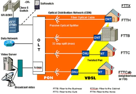
FIGURE 2.28 – DIFFERENT FTTX ARCHITECTURES [37] ... 28
FIGURE 2.30 – XGPON WAVELENGTH ALLOCATION COEXISTING WITH GPON AND VIDEO [40] ... 30
FIGURE 2.31 – MIGRATION SCENARIO FROM GPON TO XGPON [37] ... 32
FIGURE 2.32 – WAVELENGTH ALLOCATION [37] ... 33
FIGURE 2.33 – ATTENUATION OF SMF OVER WAVELENGTH RANGE [9] ... 36
FIGURE 2.34 – WAVELENGTH PLANS OF LEGACY PON SYSTEMS [9] ... 36
FIGURE 2.35 – SPECTRAL OPTIONS FOR DIFFERENT POSSIBLE COEXISTENCE SCENARIOS [43] ... 37
FIGURE 2.36 – CONCEPT OF SIGNAL OFDM [42] ... 38
FIGURE 2.37 – OCDM BASE ARCHITECTURE [42] ... 38
FIGURE 2.38 – HIGH LEVEL UDWDM NETWORK CONCEPT [46] ... 40
FIGURE 2.39 – TWDM SYSTEM ARCHITECTURE [44] ... 41
FIGURE 2.40 – WAVELENGTH ALLOCATION REUSING XGPON WAVELENGTH [49] ... 43
FIGURE 2.41 – WAVELENGTH ALLOCATION REDEFINING THE C BAND (BASED ON [49]) ... 43
FIGURE 2.42 - WAVELENGTH ALLOCATION USING C-MINUS/L-MINUS BAND [50] ... 44
FIGURE 2.43 – WAVELENGTH PLAN FOR COEXISTENCE BETWEEN GPON, XGPON, VIDEO AND TWDM [51] .. 44
FIGURE 2.44 – ODN COEXISTENCE SCENARIO [9] ... 45
FIGURE 2.45 –TRANSMITTER BLOCK DIAGRAM (A); WAVEFORM FOR INTENSITY (B); IDEAL CONSTELLATION DIAGRAM (C) AND OPTICAL SPECTRUM (D). ... 47
FIGURE 2.46 – IDEAL CONSTELLATION DIAGRAM (A); QPSK MODULATOR (B). ... 48
FIGURE 2.47 – STRUCTURE OF A QAM MODULATOR (LEFT) AND CONSTELLATION DIAGRAM OF A 16QAM SIGNAL (RIGHT). ... 49
FIGURE 3.1 – SIMULATED SETUP OF GPON IN VPI. ... 50
FIGURE 3.2 - OPTICAL SPECTRUM FOR DOWNSTREAM. ... 51
FIGURE 3.3 - OPTICAL SPECTRUM FOR UPSTREAM. ... 51
FIGURE 3.4- BER VS RECEIVED POWER FOR DOWNSTREAM. ... 52
FIGURE 3.5 - BER VS RECEIVED POWER FOR UPSTREAM. ... 52
FIGURE 3.8 – SIMULATED SETUP OF XGPON IN VPI. ... 54
FIGURE 3.9 - OPTICAL SPECTRUM FOR DOWNSTREAM. ... 54
FIGURE 3.10 - OPTICAL SPECTRUM FOR UPSTREAM. ... 55
FIGURE 3.11 - BER VS RECEIVED POWER FOR DOWNSTREAM. ... 55
FIGURE 3.12 - BER VS RECEIVED POWER FOR UPSTREAM. ... 56
FIGURE 3.13 - DOWNSTREAM MAXIMUM REACH OBTAINED FOR DIFFERENT TRANSMITTED POWER. ... 56
FIGURE 3.14 - UPSTREAM MAXIMUM REACH OBTAINED FOR DIFFERENT TRANSMITTED POWER. ... 57
FIGURE 3.15 – SIMULATED SETUP OF TWDM IN VPI. ... 58
FIGURE 3.16 - OPTICAL SPECTRUM FOR DOWNSTREAM. ... 58
FIGURE 3.17 – OPTICAL SPECTRUM FOR UPSTREAM. ... 59
FIGURE 3.18 - BER VS RECEIVED POWER FOR DOWNSTREAM WITHOUT FIBER. ... 59
FIGURE 3.19 - BER VS RECEIVED POWER FOR DOWNSTREAM WITH FIBER. ... 60
FIGURE 3.20 - BER VS RECEIVED POWER FOR UPSTREAM WITHOUT FIBER. ... 60
FIGURE 3.21 - DOWNSTREAM MAXIMUM REACH OBTAINED FOR DIFFERENT TRANSMITTED POWER. ... 61 FIGURE 3.22 - UPSTREAM MAXIMUM REACH OBTAINED FOR DIFFERENT TRANSMITTED POWER. ... 61 FIGURE 3.23 – COMPARISON OF SENSITIVITY FOR EACH TECHNOLOGY. ... 62 FIGURE 3.24 – COMPARISON FOR THE SAME TRANSMITTED POWER. ... 63 FIGURE 3.25 – COEXISTENCE SCENARIO CONSIDERED. ... 65 FIGURE 3.26 – OPTICAL SPECTRUM FOR DOWNSTREAM TRANSMISSION. ... 65 FIGURE 3.27 - OPTICAL SPECTRUM FOR UPSTREAM TRANSMISSION. ... 65
FIGURE 3.28 - BER VS RECEIVED POWER FOR DOWNSTREAM. ... 66
FIGURE 3.29 - BER VS RECEIVED POWER FOR UPSTREAM. ... 66
FIGURE 3.30 - DOWNSTREAM MAXIMUM REACH FOR TRANSMITTED POWER OF 6 DBM. ... 66
FIGURE 3.31 - UPSTREAM MAXIMUM REACH FOR TRANSMITTED POWER OF 6 DBM. ... 67
FIGURE 3.32 – EFFECT OF GPON TRANSMITTED POWER ON THE RECEIVED POWER OF EACH DOWNSTREAM CHANNEL. ... 67
FIGURE 3.33 - EFFECT OF GPON TRANSMITTED POWER ON THE RECEIVED POWER OF EACH UPSTREAM CHANNEL. ... 68
FIGURE 3.34- STATIC RAMAN EFFECT OF GPON IN THE OTHERS DOWNSTREAM CHANNELS. ... 68
FIGURE 3.35 - STATIC RAMAN EFFECT OF GPON IN THE OTHERS UPSTREAM CHANNELS. ... 69
FIGURE 3.36 – COEXISTENCE SCENARIO CONSIDERED BETWEEN TWDM AND QPSK. ... 70
FIGURE 3.37 – OPTICAL SPECTRUM OF QPSK SIGNAL. ... 71
FIGURE 3.38 - OPTICAL SPECTRUM OF THE COEXISTENCE SCENARIO. ... 71
FIGURE 3.39 – EFFECT OF QPSK SIGNAL AT 20 GBPS. ... 71
FIGURE 3.40 - EFFECT OF QPSK SIGNAL AT 40 GBPS. ... 72
FIGURE 3.41 - COEXISTENCE SCENARIO CONSIDERED BETWEEN TWDM AND 16QAM. ... 73
FIGURE 3.42 - OPTICAL SPECTRUM OF 16QAM SIGNAL. ... 73
FIGURE 3.43 - OPTICAL SPECTRUM OF THE COEXISTENCE SCENARIO. ... 74
FIGURE 3.44 - EFFECT OF 16QAM SIGNAL AT 20 GBPS. ... 74
FIGURE 3.45 - EFFECT OF 16QAM SIGNAL AT 40 GBPS. ... 75
FIGURE 4.1 – EXPERIMENTAL TWDM SCENARIO CONSIDERED. ... 76
FIGURE 4.2 – OPTICAL SPECTRUM OF TWDM TECHNOLOGY. ... 77
FIGURE 4.3 – SENSITIVITY OF TWDM DOWNSTREAM TRANSMISSION. ... 78
FIGURE 4.4 - SENSITIVITY OF TWDM FOR HIGH-TRANSMITTED POWER. ... 78
FIGURE 4.5 – EXPERIMENTAL VS SIMULATION RESULTS. ... 79
FIGURE 4.6 – BAND PASS FILTER USED IN THE EXPERIMENTAL SETUP. ... 79
FIGURE 4.7 – EXPERIMENTAL COEXISTENCE SCENARIO CONSIDERED BETWEEN TWDM AND NRZ SIGNAL. ... 80
FIGURE 4.8 – OPTICAL SPECTRUM FOR NRZ BIT RATE 10 GBPS. ... 81
FIGURE 4.9 - OPTICAL SPECTRUM FOR NRZ BIT RATE 40 GBPS. ... 81
FIGURE 4.10 – EFFECT OF NRZ AT 10GBPS ON TWDM PERFORMANCE. ... 82
FIGURE 4.11 – EFFECT OF NRZ AT 20GBPS ON TWDM PERFORMANCE. ... 82
FIGURE 4.12 - – EFFECT OF NRZ AT 40GBPS ON TWDM PERFORMANCE. ... 83
FIGURE 4.13 – LINEAR CROSSTALK FOR THE NRZ EFFECT. ... 83
FIGURE 4.14 – EXPERIMENTAL COEXISTENCE SCENARIO CONSIDERED BETWEEN TWDM AND QPSK SIGNAL. .. 84
FIGURE 4.15 - OPTICAL SPECTRUM FOR QPSK BIT RATE 20 GBPS. ... 85
FIGURE 4.16 - OPTICAL SPECTRUM FOR QPSK BIT RATE 100 GBPS. ... 85
FIGURE 4.20 - LINEAR CROSSTALK FOR THE QPSK SIGNAL EFFECT. ... 87
FIGURE 4.21 - EXPERIMENTAL COEXISTENCE SCENARIO CONSIDERED BETWEEN TWDM AND 16QAM SIGNAL. 88 FIGURE 4.22 - OPTICAL SPECTRUM FOR 16QAM BIT RATE 20 GBPS. ... 88
FIGURE 4.23 - OPTICAL SPECTRUM FOR 16QAM BIT RATE 100 GBPS. ... 88
FIGURE 4.24 - EFFECT OF 16QAM AT 20GBPS ON TWDM PERFORMANCE. ... 89
FIGURE 4.25 - EFFECT OF 16QAM AT 40GBPS ON TWDM PERFORMANCE. ... 89
FIGURE 4.26 - EFFECT OF 16QAM AT 100GBPS ON TWDM PERFORMANCE. ... 89
FIGURE 4.27 - LINEAR CROSSTALK FOR THE 16QAM SIGNAL EFFECT. ... 90
FIGURE A.1 – LOSSES DUE ATTENUATION VS WAVELENGTH OF THE FIBER. ... 100
FIGURE A.2 – CHROMATIC DISPERSION IN FUNCTION OF WAVELENGTH [62]. ... 101
FIGURE A.3 – VARIATION OF THE FREQUENCY DEVIATION, DUE TO SPM EFFECT. ... 102
FIGURE A.4 – DIAGRAM WITH THE ENERGY LEVELS OF SRS PROCESS. ... 103
Table’s List
TABLE 2.1 – PROVIDED SERVICES BY GPON DIFFERENT ARCHITECTURES [25] ... 16
TABLE 2.2 – POSSIBLE COMBINATIONS OF GPON RATE TRANSMISSION ... 17
TABLE 2.3 – PARAMETERS FOR WAVELENGTH ALLOCATION OF GPON UPSTREAM [32] ... 22
TABLE 2.4 - PARAMETERS FOR WAVELENGTH ALLOCATION OF NGA [32] ... 23
TABLE 2.5 – WAVELENGTH BANDS FOR COEXISTENCE BETWEEN GPON AND ADDITIONAL SERVICES [32] ... 24
TABLE 2.6 – DEFINED SPECIFICATIONS FOR OLT [34] ... 25
TABLE 2.7 – POWER BALANCE IN OLT AND ODN [34] ... 25
TABLE 2.8 – DEFINED SPECIFICATIONS FOR ONU [34] ... 25
TABLE 2.9 – PROVIDED SERVICES BY XGPON DIFFERENT ARCHITECTURES [38] ... 28
TABLE 2.10 – TRANSMISSION SPEEDS FOR XGPON [37] ... 29
TABLE 2.11 – WAVELENGTH BANDS ALLOCATION [37] ... 33
TABLE 2.12 – WAVELENGTH BANDS FOR COEXISTENCE BETWEEN XGPON AND ADDITIONAL SERVICES [32] .... 34
TABLE 2.13 – BIT RATE CONFIGURATIONS SUPPORTED BY NGPON2. ... 42
TABLE 2.14 – SET OF COMBINATIONS SUPPORTED BY NGPON2. ... 42
TABLE 2.15 – PHASES CORRESPONDING TO EACH SYMBOL. ... 48
TABLE 3.1 – WAVELENGTH PLAN OF TWDM. ... 58
TABLE 3.2 – COMMON PARAMETERS. ... 63
TABLE 3.3 – DEFINED PARAMETERS. ... 64
TABLE 3.4 – WAVELENGTH PLAN. ... 64
TABLE 3.5 – WAVELENGTH PLAN CONSIDERED. ... 70
TABLE 4.1 – WAVELENGTH PLAN FOR TWDM EXPERIMENTAL SETUP. ... 76
TABLE 4.2 – WAVELENGTH PLAN FOR THE COEXISTENCE SCENARIO CONSIDERED. ... 80
Acronyms list
3DTV 3D Television 40 Gbps TDM 40 Gbps Time Division Wavelength A APD Avalanche Photodiode Detector APON Asynchronous Passive Optical Network ASK Amplitude-Shift Keying ATM Asynchronous Transfer Mode AWG Array Waveguide Grating B BER Bit Error Rate BPON Broadband Passive Optical Network BPSK Binary-Phase-Shift Keying BWmap Bandwidth Map C CBU Cell-site Backhauling Unit CO Central Office CW Continuous Wave D DBA Dynamic Bandwidth Allocation DBm Decibel miliwatt DBRu Dynamic Bandwidth Report upstream DFB Distributed Feedback DML Directly Modulated Laser DRof Digitized Radio over Fiber DS Downstream DSL Digital Subscriber Line E EDFA Erbium Doped Fiber Amplifier EFM Ethernet in First Mile EPON Ethernet Passive Optical Network F FEC Forward Error Correction FP Fabry-Perot FSAN Full Service Access Network FTT Fourier Time Transform FTTB Fiber to the Building FTTCab Fiber to the CabinetFTTC Fiber to de Curb FTTH Fiber to the Home FTTO Fiber to the Office FTTP Fiber to the Premises FWM Four-Wavelength Mixing G Gbps Giga bits per second GEM GPON Encapsulation Mode GHz GigaHertz GPON Gigabit-Capable Passive Optical Network H HDTV High Definition Television HEC Header Error Control HFC Hybrid-Fiber Coaxial I
IEEE Institute of Electrical and Electronics
Engineers
IPTV Internet Protocol Television
ITU-T International Telecommunications Unit –
Telecommunication Standardization Sector J JDSU JDS Uniphase K KM Kilometer L LLID Logical Link ID M MAC Media Access Control Mbps Mega bits per second MMF Multi-Mode Fiber Ms Milliseconds MZI Mach-Zehnder Interferometer MZM Mach-Zehnder Modulator N NGPON Next Generation Passive Optical Network NGA Next Generation Access NM NanoMeter NRZ Non-Return-to-Zero
O OA Optical Amplifier OCDM Optical Code Division Multiplexing ODN Optical Distribution Network OFDM Orthogonal Frequency Division Multiplexing OLT Optical Line Terminal ONU Optical Network Unit ONT Optical Network Terminal OOK On-Off Keying OSA Optical Spectrum Amplifier P PLI Payload length indicator PMD Physical Medium Dependent PON Passive Optical Network PSK Phase-Shift Keying PTI Payload type indicator P2MP Point to Multipoint Q QAM Quadrature Amplitude Modulation QPSK Quaternary-Phase-Shift keying R RF Radio Frequency RoF Radio over Fiber RS Reed-Solomon RTD Round-trip delay RTT Round-trip time S SBS Stimulated Brillouin Scatering SiP Silicon Photodiode SLA Service Level Agreement SMF Single Mode Fiber SOA Semiconductor Optical Amplifier SPM Self-Phase Modulation SR Status Reporting SRS T TC Transmission Convergence T-CONT Transmission Container TDM Time Division Multiplexing TDMA Time Division Multiple Access THz Tera-Hertz
TM Traffic Monitoring TTA Tunable Transmitter Assembly TWDM Time and Wavelength Division Multiplexing U
UDWDM Ultra Dense Wavelength Division
Multiplexing US Upstream V VOD Video-on-Demand VoIP Voice over Internet Protocol W WBF Wavelength Blocking Filter WDM Wavelength Division Multiplexing X XGPON 10 Gigabit-Capable Passive Optical Network XPM Cross-Phase Modulation Z ZWP Zero Water Peak
1 I
NTRODUCTION
1.1 Motivation
Internet is increasingly becoming part of everyday life. This means that data networks, distributed throughout the world, have a remarkable growth in traffic. Once the traffic demands are growing much more rapidly than the available revenue, it is visible the gradual increase of the need for broadband services. In recent years, telecom operators have shown a great interest in providing various services to residential customers requiring high bandwidth, including a service called “triple-play”, which means, video, voice and data on the same network. This offer of services, such as IPTV, collects a high bandwidth due to higher quality formats such as HDTV (High Definition Television). Over time, IPTV tends to evolve to support ultra HDTV and 3DTV, which requires a bandwidth not provided by current access networks. Once arose the possibility to increase the network capacity, also appeared solutions for distribution of radio signals like RoF (Radio over Fiber) and DRof (Digitized Radio over Fiber). These solutions have reduced the complexity of the equipment and the operating costs, which created a bigger number of users and turnover.
In June 2011, it was predicted that the volume of the Internet traffic worldwide would grow sevenfold between 2010 and 2015.
Figure 1.1 - Bandwidth available to users [1]
All this continued need for bandwidth, leads to the main idea that a new transmission technology is mandatory. To meet this end, operators seeking to launch fiber deeper into the access network as far as subscriber premises – FTTP. Several studies have shown that Fiber to the Premises network is the most favorable solution in this regard, being based on the Passive Optical Network (PON) topology. [2]
The FSAN (Full Service Access Network) [3] was the first group, in 1995, working on Fiber to the Home (FTTH) architectures, which is formed by major telecommunications service providers and system vendors.
Nowadays, the most widely deployed PON standards organizations are the Institute of Electrical and Electronics Engineers (IEEE) [4] and the International Telecommunication Unit (ITU-T). [5] Have been approved some standards, currently in use, like 802.3ah EPON in 2004 [6] and G.984.1 GPON in 2008 [7], but rapidly they will not be able to satisfy the needs of the costumers. In this regard, several studies continue to be developed in order to provide higher bandwidth, higher reach and higher number of users, promoting the coexistence between each other. These new technologies are called NGPON – Next Generation PON - which are divided in mid-term and long-term solutions, NGPON1 and NGPON2, respectively. In the first one emerged the XGPON technology, ITU recommendation G.987 in 2012 [8], which is compatible with existing GPON, to reduce the cost. For the second one have been studied several technologies.
NGPON2, standard G.989.1 [9], has set some operator requirements which wants to full fill by adopting the best technology between some proposed, such as WDM, 40 Gbps TDM, OFDM, UDWDM, TWDM. The goal is clear – NGPON2 must overcome previous technologies in ODN compatibility, capacity, bandwidth and cost-efficiency. In April 2012, FSAN organization reconsidered their true aims, selecting TWDM-PON as the most attractive solution to be integrated as future technology. The prospective is to have the compliant systems ready for deployment in 2015.
1.2 Goals
The main purposes of this dissertation are:Ø Study the rules of access networks for signal distribution of GPON,
XGPON and TWDM.
Ø Characterize the technologies GPON, XGPON and TWDM, separately,
through the VPI simulator.
Ø Characterize the coexistence scenario for GPON, XGPON and TWDM,
also in VPI simulator.
Ø Demonstrate and characterize TWDM system in the laboratory.
Ø Characterize the coexistence scenario of TWDM and advanced
modulation formats.
1.3 Structure
This dissertation is organized in 5 chapters:
Ø Introduction Ø State of Art Ø Simulation Results Ø Laboratory Results Ø Conclusions and Future Work
The first chapter is written to present the framework, goals and contributions of the
Dissertation and, also, how it is structured for a better understanding.
In the second chapter, it is available the PON legacy till the present, as well the new standard to be implemented, in the near future, and its candidate technologies. It contains the features and requirements of each one, allowing the respective discussion for the migration scenarios and coexistence. At the end, it is presented some interesting acknowledgement of modulation formats and their relevance.
The third chapter has the aim of bring forward the simulation results obtained with VPIphotonics [10], starting with the characterization of each technology PON separately, including general features and limitations. After is created several coexistence scenarios to simulate the coexistence of the respective technologies between each other. The fourth chapter is regarding the laboratory experiments. Keeping the line, it is firstly characterized the TWDM system, separately and in different conditions. Posteriorly, it is carried a study about the coexistence scenarios between the TWDM system and some modulation formats available in the laboratory. For the last one, fifth chapter, it is discussed some possible future work to develop in this research area and, also, the conclusions obtained through this investigation.
1.4 Main Contributions
The main contributions were:
Ø Characterization and main features of available PON standards till the
present, as well the next generation to be implemented;
Ø Standards requirements and coexistence issues between each one;
Ø Presentation, validation and comparison between GPON, XGPON and
TWDM technologies;
Ø Coexistence scenario between each technology and fulfilled
requirements; Ø Static Raman study in the coexistence scenario of PON systems; Ø Experimental study and validation of TWDM system; Ø Coexistence scenarios of TWDM and different modulation formats. Besides, a paper under the name “Context Requirements in Future Access Networks” will be submitted in the 16th International Telecommunications Network Strategy and Planning Symposium. It addresses the study about coexistence scenarios between TWDM and high data rate formats, as QPSK and 16QAM modulation formats. Authors: Susana Bento, Simão Brandão, Ricardo Ferreira, Ali Shaphari, António Teixeira e Mário Lima.
2 S
TATE OF
A
RT
2.1 Introduction
Since 1995, the Passive Optical Networks have been studied and improved, by several groups, to provide better conditions and satisfy the users needs. This fame creates the necessity to consolidate the important role of those networks for the telecommunication operators. The big demand started with the idea of getting video, voice and data on the same network. Over the years, several standards have been approved, creating an evolution path till the present, leading to the need to go forward and upgrade the access network. In the early days of the organization, FSAN [3] developed the APON, standard G.983.1 approved in 1998, based on Asynchronous Transfer Mode (ATM) protocol. The gradual decline of ATM use leaded to the final version of ITU-T G.983.3, in 2001, being referred as Broadband PON (BPON). [11] This standard, the first one accepted, specifies a bit rate of 0.155 Gbps of uplink traffic, at 1310 nm and 0.622 Gbps of downlink traffic, at 1490nm. It is important to underline the addition of a video/RF service to this PON system, as a benefit well granted, what contributed to the history to follow this path. Figure 2.1 presents the wavelength range at this moment in the legacy. Figure 2.1 - Wavelength allocation plan in ITU-T G.983.3[12]The wavelength chosen for RF-video (1550 nm) was tight to some reasons, such as:
• Smaller attenuation loss which allows better transportation conditions and cheaper signal transmission;
• Video amplification using EDFA (relatively cheap);
• High guard band between the downstream wavelength for data and the wavelength for video, making possible the use of lasers and common filters with higher bandwidth.
The transmission was improved over the years (2002), but BPON is now an outdated technology, giving place to other.
with higher capacity, so in 2003 emerged the GPON technology giving place to the full-approved recommendation G.984.1 [7] in 2008. Following the line of the history, due to the fast growing of bandwidth demand, in 2012 was approved the G.987 standard [8] as a smooth upgrade of the previous one. Hereupon, it is possible to advertise the PON legacy – EPON, GPON, XGPON – and focus in the deployment of the Next Generation PON2.
Nowadays, the researchers are targeted to respond to the bandwidth need and bring to the world the long-term solution. Thus, after the investigation around all the candidate technologies, it appeared the one that covers the specified requirements and allows the coexistence with past technologies – TWDM-PON.
To finalize the segmentation, it is noteworthy the incoming solutions of radio signals distribution (RoF and DRoF), derived by this increase in adherence by operators to FTTH and FTTB services, and, consequently, by the development of technologies in the optical domain.
2.2 Passive Optical Networks
The major concern of the telecommunication operators relies in implementation costs of the access network. The aim is to create a positive balance between cost and bandwidth. The PON is revealing to be a technology with large-scale acquisition in the access networks market, since it can reduce the cost of equipment compared to point-to-point architectures.
PON is a point-to-multipoint, fiber to the premises network architecture in which unpowered optical splitters are used to enable a single optical fiber to serve multiple premises. It is a form of broadband access.
Figure 2.2 addresses the several possible architectures of a Passive Optical Network.
Figure 2.2 - Typical architectures of a PON network [13]
A PON consists of an OLT (optical line terminal) at the service’s provider central office (CO) and a number of ONUs (optical network units), also called ONTs (optical network terminals), near end users. Between those two nodes, which are the only points with active elements, there is the passive network, called Optical Distribution Network (ODN). By means of elimination of the active elements, it consists of one single mode fiber (SMF) and passive splitters 1:N. These four basic components have specific performance functions.
• The OLT has, as main functionality to adapt the network traffic of operator (data, voice and video) to the access network. It is responsible for management and maintenance of the ODN.
• The ONU or ONT are the same device. The first one is located in mediations of the subscriber, outside of the building and the second is located in user location. This device terminates the PON and presents customer service interfaces to the user. It can be placed in a home, office, business, and more, emerging, that way, some distinct network designations like FTTH, FTTB, and FTTC. Some ONUs implement a separate subscriber unit to provide services such as telephony, Ethernet data, or video.
• The optical fiber is the way used to diffuse the information.
• The beam splitter divides the data stream, from de CO, into the individual links to each costumer (downstream link) or connect the data sequences from all the users (upstream link).
The splitter, used to distribute the signal, cannot provide any switching or buffering capabilities, so the ONTs at the end users must perform some special functions. Once the ONUs share the same fiber, is necessary to control the multiple access channel, in the upstream transmission.
In first place, to compensate the first absence, each signal leaving the central office must be broadcast to all served users where the ONTs have to filter out signals intended for other costumers. In order to compensate the second absence, each ONT should be coordinated in a multiplexing scheme to prevent signals sent by costumers from colliding with each other. For this purpose, it can be used the WDM (Wavelength Division Multiplexing) or TDM (Time Division Multiplexing) technologies.
Wavelength Division Multiplexing is a non-standard type of PON with the aim to multiplex several optical signals in one single fiber. Thus, as it is possible to visualize in Figure 2.3, it is used several wavelengths, through lasers with different colors to carry different signals.
Figure 2.3 – WDM-PON non-standard protocol [14]
The multiple wavelengths of a WDM-PON are used to separate ONUs into several virtual PONs co-existing on the same physical infrastructure, which means that each costumer transmits their signal using a unique wavelength. This can be achieved using an Array Waveguide Grating (AWG), seen as a passive router, which will determine each optical signal to send to each port, allowing a bi-directional data flow through a single optical fiber.
Summarizing, it provides a virtual point-to-point connection between the subscriber and the central office, thereby providing many advantages of point-to-point Ethernet approach.
Being possible to use one wavelength for downstream traffic and another for upstream traffic, on a single non-zero dispersion-shifted fiber, is a great advantage. Alternatively, the wavelengths can be used collectively through statistical multiplexing to provide efficient wavelength utilization and lower delays experienced by the ONUs. [15]
In case of TDM, the costumers, with power splitters, transmit the information. On Figure 2.4, is possible to observe the data sending procedure using TDM protocol.
Substantially, the signals or bit streams, in this kind of digital multiplexing, are physically taking turns on the channel, once they are transferred appearing at the same time as sub-channels on a single communication channel. Each sub-channel has a recurrent time slot of fixed or variable length from the division of the time domain, exploring the entire bandwidth. The bandwidth available for each ONU can be established based on the need, which is checked periodically, or based on service contracts (Service Level Agreement - SLA).
Both PON approaches offer a single fiber operation in Optical Distribution Network for operational and cost reasons. The first equipment in the market was the TDM. This technique only needs one transceiver at the OLT, independent of the number of ONUs (low cost), but it means that it needs to be synchronized to avoid the signals collision. However, WDM allow longer reach and larger split ratios and the mac layer is simplified because connections realized in wavelength domain do not need the P2MP media access control. Once the transmission uses different wavelengths, it does not need any security tools. In disadvantage, the WDM components have higher costs and the wavelengths tend to drift with environment temperatures. [17]
2.3 Ethernet PON (EPON)
In November 2000, was announced a study group called Ethernet in First Mile, created by IEEE [4], which aimed to extend Ethernet to the area of the user access. In June 2004, it was improved becoming the standard IEEE 802.3ah (EPON) [6]. This network is based on Ethernet traffic transportation, working with packets of variable size, unlike the previous network, becoming very efficient. 2.3.1 Architecture EPON architecture is based on a typical access network PON. In this way, it is considerable to say that it is a fiber access technology with no active elements in the outside plant. Between the OLT and the ONU, the active elements, are the single mode fiber and the passive optical splitters 1:N to distribute the traffic to the costumers. The EPON splitter, being a passive element, does not require powering, so it is extremely stable and it never fails in virtual mode. This architecture is characterized for using WDM, to multiplex several optical carriers, in a single optical fiber, through different wavelengths.Figure 2.5 – EPON architecture [18] 2.3.2 Features Bit Rate
EFM introduced a family of Physical Layer signaling systems, derived from 1000BASE-X, including extensions like FEC (Forward Error Correction) capability. EPON specifies two physical layers for a point-to-multipoint link over one single mode optical fiber: 1000BASE-PX10 and 1000BASE-PX20. In both cases, the transmission rate is 1.25 Gbps for upstream and downstream link. [6] Line Code The PMD sub-layer service interface uses a coding line 8b/10b. It maps 8-bit symbols to 10-bit symbols to maintain the DC-balance, bounded disparity and also to allow a reasonable clock recovery. In advantage, this helps to reduce the demand for the lower bandwidth limit of the channel, necessary to transfer the signal. However, using this line coding confine the transmission rate, in reality, to symmetric 1 Gbps for both upstream and downstream traffic [6, 19]. Physical Reach
The physical reach depends on the physical layer specifications. The 1000BASE-PX10 layer uses a PIN receiver and achieves a 10 km range, whereas the 1000BASE-PX20 uses a APD receiver and achieves 20 km maximum range. [6] Split Ratio The standard 802.3ah defines a typical split ratio of 1:16. However, it can be extended to 1:32, if it is used FEC [19].
Wavelength Range
In this architecture, it is reserved for downstream traffic the 1510 nm wavelength, to send data to the users. Regarding the upstream direction, data sent by users, it is used the 1310 nm wavelength. In addition, there is another wavelength reserved for downstream video - 1550 nm wavelength. The video is encoded as MPEG2 and is carried over Quadrature Amplitude Modulated (QAM) carriers. On Figure 2.6 is presented the wavelength range for EPON data and video technologies. Figure 2.6 - Range of wavelengths for EPON standard [20] Error Correction The FEC functionality was defined as optional for some implementations, like EPON standard. Nevertheless, it is still necessary to code and decode the data flow.
This mechanism has the meaning of detect and correct errors, at the receiving end of the link that may occur when data is transferred through the link. For this purpose, when the signal is decoded, FEC uses additional data, created by a set of non-binary arithmetic functions, attaching it to the Ethernet frame.
Its usage may increase the optical link budget, making possible to have higher transmission rates and fiber distances, as well an increase of the split ratio.
In 802.3 PON standard it is recommended the use of a linear Cyclic Block code – the Reed-Solomon Code (255,239,8) – which allows the correction of 8 bytes. It can encode 239 information symbols, adding 16 parity symbols, then creating the 255 information symbols of the coded word, without any disturb. [6] 2.3.3 Transmission Downstream and Upstream Traffic
The Ethernet PON has different techniques to send data from the OLT to multiple ONUs – downstream transmission – and to send from multiple ONUs to the OLT – upstream transmission.
Figure 2.7 – Downstream traffic flow in EPON [21] Observing Figure 2.7, it is possible to understand that several packets, with variable length, are broadcast to the ONUs, in downstream transmission. According to 802.3ah protocol, the load size reaches from 46 to 1518 bytes. Each packet carries a header with information about the addressee, as is possible to verify in Figure 2.8. All the ONUs receive the same packets, each one accepting only the ones that are intended for the respective user and discarding the others. This is accomplished through the field LLID, embedded in the frame.
Figure 2.8 – Downstream frame format EPON [21]
Regarding to the upstream traffic, it is used a multiple access protocol – TDMA: Time Division Multiple Access – where transmission time slots are dedicated to each ONU. Thus, all the information is multiplexed and sent to the OLT.
In this order, once the data is coupled on the same fiber, the time slots must be synchronized to avoid collisions between packets from each ONU. Figure 2.9 presents the schematic oh the referred procedure.
Figure 2.9 – Upstream traffic flow in EPON [21]
The upstream traffic is divided into frames, identified by a header with a
transmission interval of 2ms. This can be observed in Figure 2.10. Each frame has the ONU-specific time slots, which are dedicated to the transmission of the variable-length packets from the time slots of the respective ONU. The OLT and the TDM
Figure 2.10 – Upstream frame format EPON [21] Ranging
Ranging is the necessary mechanism to guarantee the synchronization between every ONUs slot and the assigned OLT slot, by calculating the RTT (round-trip time).
From the point of view of the OLT, it is possible to occur transmission overlap of upstream data, due to the different distances of each ONU. This could lead to changes in the RTT, by changes of time and environment.
In order to avoid the collision of upstream data, RTT is measured, based in time stamps, and inserted with the corresponding equalization delay to put the same virtual distances between OLT and ONUs.
Figure 2.11 – EPON ranging process [22]
The ranging process, illustrated on Figure 2.11, involves one single phase, with changes at the OLT side, and is described in the following steps:
1) The OLT sends a GATE message with the timestamp T1, to inform the ONU when to start the transmission;
2) The ONU receives the GATE message at local time T2, after the
transmission delay - Tdownstream, and resets its timer to T1.
3) The ONU sends, after some time – TWAIT, a REPORT message at local
time T3, with timestamp T4 – T1 = T3 – T2. In practice, it corresponds to a change in the value of the local clock;
4) The OLT receives the report at local time T5 and calculate RTT, which is simply RTT = T5 – T4 (difference between the local watch value, when received REPORT message T5, and the value of the timestamp received in that message). Figure 2.12 – RTT calculation (IEEE 802.3ah) [23] Auto Discovery The auto discovery process allows newly ONUs entrance and register in the system, without manual intervention and without affecting other ONUs. This is possible because the OLT periodically propagates discovery Gate frames, granting a discovery window, where each ONU can provide independently some parameters, like LLID and RTT. The process of auto discover is presented in Figure 2.13. Figure 2.13 – Auto Discover Process [22] When an ONU intends to register, in first place, it receives the discovery gate message and responds with a register request, after a random delay. Then, the OLT allocates the ONU with the LLID, sending a gate frame to grant the upstream time slot for transmission. At last, the ONU sends a register acknowledgement frame to the OLT, establishing the communication channel and finishing the process.
It is possible to have requests from multiples ONUs at the same time, because it is added, to each one, a random delay, before sending the register frame
2.4 Gigabit PON (GPON)
There are more and more people using Internet nowadays, what is generating more demand for very high bandwidth. In 2001, became necessary to study a technology capable of incorporate an important feature feed by the needs of operators, which is the ability to upgrade legacy deployments without interrupting service for existing users.
In 2003, emerged the standard GPON (Gigabit-Capable Passive Optical Network), becoming the full recommendation ITU-T G.984.1 [7] in 2008. Seen as an upgrade from BPON [11], it represents an improvement in bandwidth efficiency by the use of larger and variable length packets. GPON, also called “triple play”, allows having Internet, Image in high definition and telephone, replacing the current cooper network IPTV and ADSL. It allows to the consumers the possibility to see all channels in high definition and at three dimensions. 2.4.1 Architecture GPON architecture is based on a typical access network PON. In this way, it is considerable to say that it is a fiber access technology with no active elements in the outside plant. Between the OLT and the ONU, the active elements, there is the single mode fiber and the passive optical splitters 1:N to distribute the traffic to the costumers. The GPON splitter, being a passive element, does not require powering, so it is extremely stable and it never fails in virtual mode. It is characterized for using WDM, to multiplex several optical carriers, in a single optical fiber, through different wavelengths. Figure 2.14 – Scheme of GPON network [24]
As observed in Figure 2.14-15, GPON network can embrace multiple architectures where the differences between each one are the services supported. The typical architecture is FTTH however, operators seeking to launch fiber deeper into the access network either to a short copper drop (FTTC/FTTB) or as far as
• FTTB - Fiber to the Building - refers to installing optical fiber from the telephone company central office to a specific building such as a business or apartment house and FTTB.
• FTTC – Fiber to the Curb - refers to the installation and use of optical fiber cable directly to the curbs near homes or any business environment as a replacement for "plain old telephone service". • FTTP – Fiber to the Premises - networks are based on the passive
optical network (PON) topology with a passive optical fiber power splitter deployed close to the end user.
Figure 2.15 – Different GPON architectures [7]
On table 2.1, available services and characteristics of different GPON architectures are presented in other to make a better comparison. FTTB Companies FTTB for MDU FTTC FTTCab FTTH Provided services Asymmetric broadband services
û ü ü ü ü Digital services, Video on Demand radio diffusion (VoD), online games, files download.
Symmetric broadband services
ü ü ü ü ü Content transmission, email for files exchange, distance learning, telemedicine.
POTS and ISDN ü ü ü ü ü Must be capable to provide narrow band services by
telephone, in a flexible way, with the right moment for introduction.
Private line
services ü û û û û Must be capable to provide private line services and
multiple rates, in a flexible way.
xDSL backhaul
û û ü ü û
2.4.2 Features Bit Rate This standard is able to define several transmission speed combinations, like is presented in table 2.2: Bit Rate (Gbps) Upstream 0.155 0.622 1.244 0.155 0.622 1.244 2.488 Downstream 1.244 1.244 1.244 2.488 2.488 2.488 2.488 Table 2.2 – Possible combinations of GPON Rate transmission However, it has the aim to achieve values of 1.2 Gbps or higher. So, the most common bit rate, which is currently supported, is 1.244 Gbps upstream and 2.488 Gbps downstream, shared among users. [7] Line Code
The line code, used in G.984 in both ways of transmission, is NRZ (non-return-to-zero) with scrambling. With NRZ, the receiving clock can lose synchronization due to the lack of transitions in consecutive identical digits (CID). In this way, it is used the scrambling technique, to pseudo randomizing a data stream and trying to avoid long sequences of identical digits. [7] Physical and Logical Reach The physical reach corresponds to the maximum physical distance between the OLT and an ONU. The GPON technology defines two possible values for this parameter: 10 and 20 km. In case of use a Fabry-Perot laser diode, which is a low cost solution, it is assumed 10km as the maximum distance.
The logical reach corresponds to the maximum distance between the OLT and ONU, except for the limitation of the physical layer. It can achieve values till 60 km, in the maximum. [7]
Split Ratio
The passive optical splitter can be in the order of 1:32, 1:64 and 1:128. However, higher the split ratio higher is the optical splitting and, consequently, higher is the power budget needed to cover the physical reach.
In this order, 1:64 is the normal split ratio defined for the current GPON technology. Despites the 1:128 is still not in use, it is an option for the continued evolution of the optical modules. [7]
Wavelength Range
With the WDM protocol, the G.984.1 standard uses different wavelengths for upstream and downstream traffic, with a single fiber. The wavelength plan enables the co-existence of ITU-T standards compliant PONs.
EPON and GPON have the same basic wavelength plan. For the downstream traffic, it is defined the 1490 nm wavelength (1480 to 1500) and for the upstream traffic the 1310 nm wavelength (1260 to 1360).
An additional wavelength plan, 1550 to 1560 nm, is reserved for optional overlay services, typically RF (analog) video, in downstream direction. [20]
Error Correction
The FEC functionality was defined as optional for some implementations, like GPON standard. In case of being disabled, an ordinary data is transmitted. Nevertheless, it is still necessary to code and decode the data flow.
In G.984 PON standard it is recommended the use of a linear Cyclic Block code – the Reed-Solomon Code (255,239,8) – which allows the correction of 8 bytes. It is able to encode 239 information symbols, adding 16 parity symbols, then creating the 255 information symbols of the coded word, without any disturb.
Forward Error Correction is used in GPON to improve optical link budgets, giving about 3-4 dB extra margin, and to reduce user data in 6%. While without FEC the G.984 requires BER not worst than 10-10, with FEC it is possible to improve it to 10-4. [26] 2.4.3 Transmission Upstream and Downstream Traffic
For the downstream transmission, the traffic is broadcast from the OLT to ONU in fixed GEM (GPON Encapsulation Mode) frames of 125 µs. Every ONU receives the same data, so they need to distinguish which traffic is destined to each one. This is accomplished through the field GEM port ID, embedded in the frame, allowing the filtering data that is not addressed. This procedure is presented in Figures 2.16-17.
Figure 2.17 – Downstream GPON frame [28] Regarding the upstream traffic, to avoid collisions between packets, it is used the TDMA protocol. The OLT assigns variable length time slots to each ONU with the aim to synchronize the data bursts transmission, as shown in Figure 2.18. The field Upstream Bandwidth Map (BWmap) sent in the downstream frame, dictates, according to its content, the attribution of the time slots. Figure 2.18 - Upstream transmission traffic [27] Figure 2.19 – Upstream GPON frame [28] Ranging
In the upstream direction, the PON is a multipoint-to-point network, multiplexing data with TDMA. Giving that the distance from the OLT to each ONU is different, if every ONU start to transmit itself, the signal may overlap, since the delay propagation is different. Thus, to achieve an exact synchronization between the elements of the network, the standard G.984.1 uses the ranging mechanism.
Ranging is the process of measuring or calculating a specific delay for every ONU. This method can operate in two ways:
• Initial ranging: performed at ONU boot-up or upon ONU discovery, before the ONU transmits first time.
• Continuous ranging: performed continuously to compensate for delay changes.
In GPON, this mechanism it is preceded in two phases, where the changes are made in the ONU side. In the first step, demonstrated in Figure 2.20 it is
Figure 2.20 – GPON ranging phase 1: serial number process [29]
For the second phase, shown in Figure 2.21, the OLT measures the round-trip delay (RTD) to the ONU. Then, the signal transmission timing of each ONU is adjusted according to this RTD so that the signals from individual ONUs arrive at different times and do not overlap. Figure 2.21 – GPON ranging phase 2: delay measurements [29] Dynamic Bandwidth Allocation
Dynamic bandwidth allocation (DBA), as focused on Figure 2.22, is used to reassign bandwidth volume to ONUs, based on current traffic requirements. This methodology, which is controlled by the OLT, only works in upstream transmission. Figure 2.22 – Dynamic Bandwidth Allocation [30]
To start the process, the OLT needs to have information about the traffic status of each ONU. In this regard, each ONU has associated a transceiver T-CONT to indicate how many packets are waiting in its buffer. The status is reported in a field called DBRu, which is used to notify to MAC controller a transmission attribution. When the OLT has this information, it is able to determine how much traffic to assign to an ONU, through a management of grants accordingly.
In case of an ONU being empty, it will inform that there is no data to be sent, with an idle cell upstream and the T-CONT grant can be provided to others. [28]
Figure 2.23 presents a scheme of DBA in order to understand better the process. Figure 2.23 – DBA process [28] Data Encapsulation Method The standard G.984.1 defined the GEM, as an encapsulation method for data transportation. It provides the Generic Frame, constituted by 5 headers: • 12-bit Payload length indicator (PLI) – specifies payload length in bytes; • 12-bit Port ID – gives the port numbers for traffic multiplexing; • 3-bit Payload type indicator (PTI) – indicates if the payload has user data frame or OAM frame; • 13-bit Header Error Control (HEC) – maintains frame synchronization and integrity protection; • L-byte GEM fragment Payload
GEM frame encapsulation has the function of multiplex ports and payload data fragmentation. In this way, it became very efficient because enables GPON to transport TDM and variable length packets, both carried in the Generic Frame, over fixed data-rate channels, without ATM. [29] 2.4.4 Wavelength Coexistence Issues In recommendation G.984.5 [31], approved in 2007 by ITU-T Study Group [5], was redefine the wavelength ranges, reserved for additional service signals, to be overlaid in future with next generation services – NGA and video. For this purpose, it
Figure 2.24 – Wavelength allocation [31]
In first place, outward in Figure 2.24, the operating wavelength is redefined as basic band to downstream signal and enhancement band for reserved bands, with a guard band between each other. It is used a WBF (Wavelength Blocking Filter) to provide isolation outside the guard band, due to the signal degradation caused by the interference between the two bands.
Notice that, the wavelength range for video and downstream transmission remains the same as defined previously.
Secondly, regarding to the upstream wavelength band, this can occupy three possible options in O band, with width of 20 nm, 40 nm or 100 nm, named as narrow, reduced and regular, respectively. This is possible to visualize in Table 2.3.
Limit Notation Unit Nominal
Value Application examples 1.3 μm wavelength band For use in GPON upstream. - Regular wavelength band option e.g., ONUs based on Fabry-Perot lasers. Lower limit λ 1 nm 1260 Upper limit λ 2 nm 1360 - Reduced wavelength band option e.g., ONUs based on ordinary DFB lasers. Lower limit λ 1 nm 1290 Upper limit λ 2 nm 1330 - Narrow wavelength band option e.g., ONUs based on wavelength selected lasers. Lower limit λ 1 nm 1300 Upper limit λ 2 nm 1320 Table 2.3 – Parameters for wavelength allocation of GPON upstream [32] At last, concerning to the next generation services, presented in Table 2.4, were also defined three possible options, two in E+ band and the other in C and L band.
Bands for Next Generation Services (NGA)
Limit Notation Unit Nominal
Value Application examples Enhancement band (option 1-1) Applicable for low-water-peak fibers (informative values). Lower Limit λ 3 nm 1415 Upper Limit λ 4 nm 1450 Enhancement band (option 1-2) Applicable for low-water-peak fibers only (informative values). Lower Limit λ 3 nm 1400 Upper Limit λ 4 nm 1450 Enhancement band (option 2) Upper limit determined by choice of the operator considering some factors. Lower Limit λ 5 nm 1530 Upper Limit λ 6 nm 1580 to 1625 Table 2.4 - Parameters for wavelength allocation of NGA [32] Even with the coexistence of NGA and video, the signals interference in the enhancement band must allow to be known the minimum optical sensitivity. In this order, the ONUs must isolate the interference between signals, using filters with specific isolation characteristics, to guarantee minimum interference effect.
Following, the recommendation G.984.5 presented the X/S tolerance mask – Figure 2.25 - (X – maximum power of interference signal, S – received power of basic band signal) of the GPON ONU, without exceeding the limit for the sensitivity of the basic band receiver. The signal is measured in NRZ pseudo-random format, which can be coded in two options: with the same bit rate as GPON downstream signal or a lower rate within the bandwidth of the basic band receiver. [31]
Figure 2.25 – S/X tolerance mask for ONU [31]
Another coexistence scenario, allowing the coexistence between GPON, video and NGA services is shown in Figure 2.26. It takes into consideration the possible video CNR performance degradation that may be caused by interference. With the aim to avoid that, arise the idea of introduce guard bands in both sides of the video band, which will have ranges dependent on filter characteristics of the
![Figure 2.3 – WDM-PON non-standard protocol [14]](https://thumb-eu.123doks.com/thumbv2/123dok_br/15967571.1100682/34.892.260.708.111.380/figure-wdm-pon-non-standard-protocol.webp)
![Figure 2.5 – EPON architecture [18]](https://thumb-eu.123doks.com/thumbv2/123dok_br/15967571.1100682/36.892.269.658.113.401/figure-epon-architecture.webp)
![Figure 2.14 – Scheme of GPON network [24]](https://thumb-eu.123doks.com/thumbv2/123dok_br/15967571.1100682/41.892.278.677.697.984/figure-scheme-gpon-network.webp)
![Figure 2.24 – Wavelength allocation [31]](https://thumb-eu.123doks.com/thumbv2/123dok_br/15967571.1100682/48.892.302.693.130.376/figure-wavelength-allocation.webp)
![Table 2.5 – Wavelength bands for coexistence between GPON and additional services [32]](https://thumb-eu.123doks.com/thumbv2/123dok_br/15967571.1100682/50.892.165.778.397.925/table-wavelength-bands-coexistence-gpon-additional-services.webp)
![Table 2.12 – Wavelength bands for coexistence between XGPON and additional services [32]](https://thumb-eu.123doks.com/thumbv2/123dok_br/15967571.1100682/60.892.125.788.176.485/table-wavelength-bands-coexistence-xgpon-additional-services.webp)
![Figure 2.33 – Attenuation of SMF over wavelength range [9]](https://thumb-eu.123doks.com/thumbv2/123dok_br/15967571.1100682/62.892.254.699.113.390/figure-attenuation-smf-wavelength-range.webp)
![Figure 2.35 – Spectral options for different possible Coexistence scenarios [43]](https://thumb-eu.123doks.com/thumbv2/123dok_br/15967571.1100682/63.892.207.751.238.537/figure-spectral-options-for-different-possible-coexistence-scenarios.webp)
![Figure 2.39 – TWDM system architecture [44]](https://thumb-eu.123doks.com/thumbv2/123dok_br/15967571.1100682/67.892.265.653.678.995/figure-twdm-system-architecture.webp)
