ISSN 1517-7076 artigo e-11851, 2017
Corresponding Author: Fabiane Valente Härter Received on: 22/11/2016 Accepted on: 01/02/2017
10.1590/S1517-707620170002.0167
Transverse permeability determination
and influence in resin flow through an
orthotropic medium in the RTM process
Fabiane Valente Härter1, Jeferson Avila Souza1,
Liércio André Isoldi1, Elizaldo Domingues dos Santos1
Sandro Campos Amico2
1 PPGMC – FURG CP: 96203 – 900, Rio Grande, RS
e-mail: [email protected]; [email protected]; [email protected]; [email protected];
2PPGEM – UFRGS – Box 15010, CP: 91501 – 970, Porto Alegre, RS
e-mail [email protected]
ABSTRACT
Resin Transfer Molding (RTM) process is commonly used to produce high quality polymeric composites with simple or complex geometries in small to large sizes. In RTM process a preformed reinforcement is positioned inside the mold cavity. This dry reinforcement is actually a fibrous porous media whereby resin will flow. The mold is then closed and resin is injected. After complete impregnation of the reinforcement, resin cure process takes place. Numerical simulation is a very useful tool for mold design and process optimization, however resin and reinforced medium physical properties must be precisely determined. Medium permeability is probably the most important and most difficult parameter to be evaluated. In this work it is proposed a numerical/experimental methodology to determine transverse permeability in reinforcements used within RTM process. PAM–RTM software was chosen to simulate resin flow through the reinforced medium. Proposed methodology uses the inverse parameter estimation method to calculate the unknown permeability. Newton-Raphson method was used to solve the associated algebraic equation system, on which PAM–RTM software is used to calculate resin injection times. Results have shown that with previous knowledge (taken from literature or obtained experimentally) of the in-plane permeabilities (Kxx and Kyy), physical properties of the resin (ρ, µ), medium porosity (ε) and total filling time (t) it is possible to
estimate transverse permeability in thick pieces. It was also performed a numerical study about the influence of transverse permeability in resin flow inside the mold. This study predicted several possible problems that may occur when transverse permeability is much smaller than in-plane permeabilities. Finally, it is possible to state that mold design and proper fibrous reinforcement choice can be optimized when numerical techniques are used.
Keywords: Transverse permeability, anisotropic medium, RTM, PAM-RTM.
1. INTRODUCTION
Resin Transfer Molding (RTM) [1] is a manufacturing process used to produce polymeric composites of high quality in a large variety of sizes and simple to complex geometries. In RTM process a fibrous reinforcement medium is placed inside the mold cavity. This dry reinforcement is actually a porous medium on which a polymeric resin will be forced to flow through. The mold is closed and resin is injected in mold cavity until it is completely filled. When resin curing process ends, the mold is opened and the finished piece is removed. Resulting composite combines low weigh with good mechanical properties.
Due to the large possible combinations of different resins and reinforcements, polymeric composite materials may take advantage of the best (or desired) quality of a resin in combination with the best property of a reinforcement, producing a final piece that combines these qualities. This characteristic makes polymeric composites an attractive alternative for a variety of applications.
Currently, polymeric composite materials may be found in cars, boats, airplanes, medical prostheses, sports equipment, among many others applications. They have been also replacing traditional materials (like metal) in many engineering applications [2].
(mold design). These are all important information needed to guarantee the quality of the final produced composites. However, realistic numerical predictions are only possible if precise information about physical properties of resin and reinforcement are known. Moreover, the great majority of numerical models used to simulate resin flow in RTM process are based on Darcy's Law, thus medium permeability and resin viscosity are key properties that must be known [3]. The proper determination of medium permeability is decisive for the numerical simulation of real engineering problems.
There are many studies about permeability determination of reinforced mediums used in RTM. Most of them concentrate in study the in-plane permeabilities (Kxx e Kyy) ([4]–[11]), however it is possible to find
many studies about the transverse permeability (Kzz) ([12]–[16]). Transverse permeability determination is
more complex than in-plane permeability determination, thus it is reasonable that less works are focus on this topic [17].
There are two types of experiments that are mostly used for permeability determination. They are known as saturated and unsaturated methods. Saturated methods are assembled in such way that a continuous fluid flow (resin or oil) is forced through the reinforced medium [18]. Volumetric flow rate and pressure gradient are experimentally measured and Darcy's Law is used to calculate the permeability. Unsaturated methods differs from the former method in a way that flow front position is tracked (as a function of time) during its advance through the medium. In this kind of method, measurements are made in a dry medium, i.e. at exact point that the fluid reaches the sensor [19].
Taking into account only transverse permeability measurements, as an example of unsaturated methods it is possible to refer to the work of [18] on which an experimental setup was built with this objective. In [18] five pressure sensors were positioned along thickness direction and flow front advance is registered, as a function of time, by the activation of these sensors. In this work authors have also measured in-plane permeability and observed that, for the tested fibers, transverse permeability is about one order of magnitude smaller than in-plane permeability.
Saturated methods are more commonly used in transverse permeability determination. A recent work presented in [19] proposes the use of an Instron 1186 Universal Testing Machine (UTM) to control the reinforced thickness. Once reinforced thickness can be changed with the UTM, different volume fractions can be set concurrently to the permeability test, making easy to perform in-depth study of the compaction-permeability relationship. An experimental/numerical model is proposed by [16] to determine 4 components (Kxx, Kxy, Kyy and Kzz) of the permeability tensor in a 3D injection. A flow simulation (using LIMS - Liquid
Injection Molding Simulation application) was combined with the Golden Section Search Minimization Technique to calculate permeability components. Results are validated by direct comparison with experimental data provided in the same work. Recently, a similar work has been presented by [15] to determine 6 components (Kxx, Kyy, Kzz, Kxy, Kxz, Kyz) of the permeability tensor. The method is similar to that
proposed by [16] however LIMS simulation is now combined with the simple optimization algorithm. This work concentrates in developing a methodology to calculate the transverse permeability in reinforced mediums used with the RTM process. Inverse parameter estimation method is used to calculate the unknown transverse permeability. Pressure and flow position are measured experimental and the mathematical model is solved for the permeability. Newton-Raphson method for the solution of algebraic system of equations is combined with a CFD (Computational Fluid Dynamics) solution in order to calculate the desired permeability. It was also performed a numerical study about the influence of transverse permeability in resin flow inside the mold. This study predicted several possible problems that may occur when transverse permeability is much smaller than in-plane permeability. Usually, transverse permeability is one to three orders of magnitude smaller than in-plane permeability. In this study in-plane permeability is kept constant and transverse permeability is made to vary from 1 to 10,000 times smaller. Geometry and discretization were performed with GMSH software ([20], [21]), while flow advance was determined with PAM-RTM software [22].
2. PROBLEM DESCRIPTION
Resin advance inside mold cavity can be modeled as a porous media flow. Darcy's Law, which correlates flow velocity with pressure gradient, is usually used to formulate and solve, this kind of physical problem. In mathematical terms, for constant permeability and viscosity, Darcy's Law ([23], [24]) is presented as
where is the average fluid velocity [m/s], K the medium permeability [m2], μ the resin viscosity [Pa s] and P the pressure [Pa].
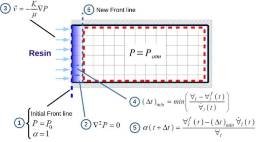
In RTM problems, there are two types of formulation commonly used: VOF (Volume of Fluid) [25] and FE/CV (Finite Element/Control Volume) with FAN Technique [26]. In present work, PAM-RTM software has been used to solve the porous media fluid flow problem. It is a software dedicated to solve industrial and academic problems and for this reason it has an easy to use Graphical User Interface. It can solve problems related to RTM process and its variants. Solver capabilities include fluid flow solution in porous medium, resin cure modeling, isothermal and non-isothermal solutions, among others. PAM-RTM manual [22] do not explicitly explains the used methodology, however based on results and solver input parameters it is possible to imply that a FE/CV like method is used. In this formulation, only one fluid (resin) is considered.
FAN Technique allows to solve the transient problem by a sequential solution of steady state problems. It tracks resin advance by solving a Laplace equation for pressure combined with Darcy's Law. In this method, mass conservation equation for an incompressible fluid
0 (2)
is combined with Darcy's Law (Eq. (1)) resulting in a Laplace equation for the pressure field
0 (3)
In a simplified form, this method can be described in 6 steps as follows:
step 1. Initial conditions (mold is empty with pressure equal to zero) and boundary conditions (prescribed
pressure at inlet section, prescribe pressure equal to zero at flow front and zero gradient in all other surfaces) are set;
step 2. Equation (3) is solved to determine pressure field inside the mold;
step 3. Equation (1) is used to calculate velocity field. With this velocity field it is possible to calculate resin
flow rate entering (or leaving) every control volume of the flow front;
step 4. Minimal time necessary to fill at least one control volume is calculated
∆ ∀ ∀∀ (4)
where ∀ is the volume for grid cell i [m3], ∀ the volume of resin in grid cell i at time t [m3] and ∀
the resin volumetric flow rate in grid cell i and time t [m³/s].
step 5. Volume fraction, of all flow front volumes are calculate by
∆ ∀ ∆∀ ∀ (5)
step 6. New control volumes with = 1 are now added to the flow front and solution returns to step 2. These
five steps (2 to 6) must be repeated until all control volumes in the grid are filled with resin (= 1).
Figure 1: Schematic representation of the FE/CV algorithm
3. PROPOSED METHODOLOGY FOR TRANSVERSE PERMEABILITY DETERMINATION
Computational domain is shown schematically in Fig. 2. It represents a squared thick plate with side length b
equal to 0.25 m and height H equal to 0.05 m. The injection gate (radius equal to 0.005 m) was placed at the
bottom center of the domain.
At the inlet gate, prescribed pressure have been set. For all other boundaries, normal to the surface pressure derivative (dp/dn) was set to zero. In this formulation there is no need to specify any outlet gate.
Figure 2: Computational domain
Permeability is a reinforced medium property used to measure (quantify) how easy a fluid is able to pass through a porous medium. It is a function of the fabric material and the compression imposed by the mold closing. Average values taken from literature for the physical properties and operating parameters set to current problem are presented in Tab. 1.
Table 1 – Parameters used in all simulations
PARAMETER VALUE UNIT
Injection pressure (P0) 0.50 x 10⁵ Pa
Injection radius (r) 5.00 x 10⁻³ m
Resin viscosity () 0.06 Pa s
Medium porosity () 0.70 dimensionless
Medium in-plane permeability (Kxx = Kyy) 3.00 x 10⁻¹⁰ m2
Injection Gate (r = 0.005 m)
b = 0.25 m b = 0
.2 5 m
Current methodology was designed to be used with experimental data. Main goal is to calculate transverse permeability by combining a small number of experimental measurements with a numerical solution. However, in order to evaluate the method, the mold filling time, texp, is actually a previous solution
obtained with PAM-RTM on which Kzz is prescribed. This procedure insures that the difference between
correct (prescribed) and numerical calculated permeability values measures the real capability of the method in solving the inverse problem, i.e., no experimental errors (or imprecision) are accounted to the error estimation. Thus, from this point in text, texp, which is the numerical reference solution, will be named as
experimental time.
After the mold is completely filled with resin, by assuming that texp is the injection time
experimentally measured and that tnum is the flow time numerically calculated, it is possible to write a residue
equation such as
, 0 (6)
In Eq. (6), in-plane permeability (Kxx and Kyy), and physical properties of the resin (viscosity) and
medium (porosity) are considered constant and known.
Using the Newton-Raphson method [27], Eq. (6) can be solved for Kzz by
,
, (7)
where n is the iteration, f a function representing the numerical method and f ' the derivative of f.
In Eq. (7), the derivative is numerically approximated by
, , , , (8)
where h is a constant used to evaluate the derivative and set to 1 x 10-15.
4. RESULTS
As described in section 3, proposed methodology was designed to use experimental data in order to solve Eq. (6), however in this work texp has been calculated with PAM-RTM software. Theoretical experiment starts by
defining a transverse permeability to the medium and then running a simulation to determine texp. This
procedure does not invalidate the proposed methodology, because texp is only a reference value to which
solution of Eq. (6) must converge.
It was defined Kzz = 3 x 10 -10 m² and resin injection was simulated up to the time that the mold is
completely filled with resin. Calculated time for this condition was texp = 512.99 s.
Equation (6) is then solved for Kzzwith the Newton-Raphson method. It is important to highlight that each time that tnum is called by the Newton-Raphson algorithm, it is necessary to solve Eq. (2), what is done
with the Finite Element Method using the PAM-RTM software.
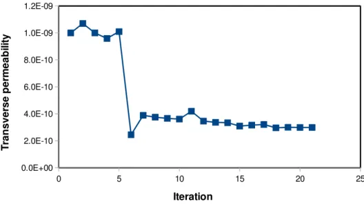
Convergence log is shown in Tab. 2. It is recommended to have an initial guess as close as possible to the real permeability, however this is not a constraint to the proposed method. In current experiment, Kzz was
initially set to 1 x 10 -9 m² which is one order of magnitude larger than the aimed value of
Kzz (3 x 10 -10 m²)
and it was necessary 21 iterations to reach a relative error smaller than 1 %. If a better guess (closer to the aimed permeability) were chosen, less iterations will be necessary, however the idea in this numerical experiment was to show the “robustness” of the proposed methodology.
Calculated Kzz value is 2.99 x 10⁻¹⁰ m² while the aimed value was 3 x 10 -10 m² leading to an error in
determine Kzz of approximated 0.5 %.
Analyzing Tab. 2 it can be seen that convergence is stable. Figure 3 shows a plot of calculated transverse permeability Kzz as a function of the number of iterations. A small oscillation can be seen in the
Table 2. Convergence log for the inverse problem solution
ITERATION Kzz(m2) Error (%)* ITERATION Kzz(m2) Error (%)*
1 1.00e-009 - 12 3.46e-010 -21.15
2 1.07e-009 6.66 13 3.37e-010 -2.77
3 1.00e-009 -6.96 14 3.34e-010 -0.92
4 9.59e-010 -4.41 15 3.09e-010 -8.08
5 1.01e-009 5.01 16 3.16e-010 2.22
6 2.45e-010 -313.01 17 3.21e-010 1.56
7 3.89e-010 37.12 18 2.96e-010 -8.47
8 3.75e-010 -3.61 19 3.00e-010 1.23
9 3.66e-010 -2.67 20 2.99e-010 -0.23
10 3.61e-010 -1.21 21 2.99e-010 0.07
11 4.19e-010 13.89
* error = 100 x (Kn+1 – Kn)/Kn+1 where n is the iteration
Figure 3: Transverse permeability Kzz versus iteration for the Newton-Raphson solution of Eq. (6)
Proposed algorithm was applied to a simple geometry, however it can predict final piece permeability for any complex geometry. The only difference is associated with the difficult, and simulation time, needed to solve the injection problem. Flow solution depends both on the number of mesh elements and the quality of these elements. Discretization of complex geometries usually requires large meshes with irregular elements, consequently, longer simulation times are required. Important to say that flow problem is solved several times for each Newton-Raphson iteration.
4.1 Influence of transverse permeability in resin flow in the RTM process
Geometry of the problem is the same presented in Fig. 2, but with different dimensions. For the following simulations b = 0.30 m, H = 0.0254 m (1 inch) and r = 0.005 m. A grid independence test has been
performed (not shown for brevity) and the independent grid has 57362 tetrahedral elements. Injection
0 5 10 15 20 25
0.0E+00 2.0E-10 4.0E-10 6.0E-10 8.0E-10 1.0E-09 1.2E-09
Iteration
T
ran
sver
se p
er
m
eab
il
it
pressure and physical properties (average values observed in literature) used have also changed and are shown in Tab. 3.
Table 3 – Parameters used in all simulations
PARAMETER VALUE UNIT
Injection pressure (P0) 0.50 x 10⁵ Pa
Resin viscosity () 0.50 Pa s
Medium porosity () 0.50 dimensionless
Medium in-plane permeability (Kxx = Kyy) 1.0 x 10⁻⁹ m2
Table 4 shows commonly values for transverse permeability taken form different references ([12], [13], [28], [29]). It shows that depending on fabric type and volume fraction (VF), transverse permeability may vary from 1 x 10⁻¹⁰ m2 to 1 x 10-13 m2.
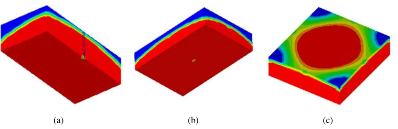
Five case studies have been proposed. In order to show the isotropic 3D case, transverse permeability is made to vary from 1 x 10⁻⁹ m2, same as the in-plane permeabilities, to 1 x 10-13 m2. In each solution, flow front advance is shown and discussed. In Figs. 4 to 9, red indicates resin ( = 1), blue indicates air ( = 0) and other colors indicate the interface between resin and air (0 < < 1). It is important to highlight that this model does not solve any equation for the second phase (air), thus blue color actually indicates an empty space.
Table 4: Transverse permeability values taken from literature
Fabric Volume Fraction (%) KZZ [m²] Reference
Glass fiber E 45-70 3x10⁻¹⁰ to 1x10-13 [12]
Glass fiber E 50 3x10-13
[28]
Kevlar 50 1x10-13
Several 20-50 5x10-11 to 1x10-13 [29]
TET-450 45-62 4x10⁻¹⁰ to 6x10-13 [13]
4.1.1 Case study 1 (Kzz = 1 x 10⁻⁹ m2)
In this case, transverse permeability was set equal to the in-plane permeability. Figure 4 shows flow advance views from the bottom of the mold and a cut at the middle section. In Fig. 4a it is clear that this flow is symmetric, but in Fig. 4b (because of the angle of the view) it seems that fluid advances faster in transverse direction, however flow front forms a sphere. Monitor sensors positioned along x and z axes confirm this
expected behavior for an isotropic porous medium (Kxx = Kyy = Kzz = 1 x 10⁻⁹ m2).
(a) (b)
Figure 4: Flow front visualization for Kzz = 1 x 10⁻⁹ m2 at 4 s: (a) bottom view (b) middle section cut
Figure 5 shows flow advance for t = 63 s and t = 610 s. In Fig. 5a it is possible to verify that medium
A close to end of the resin injection process is shown in Fig. 5b. In this figure it is possible to observe that the four corner edges will be the last regions to be impregnated with resin, indicating the possible location for the mold vents (blue regions).
(a) (b)
Figure 5: Flow front visualization for Kzz = 1 x 10⁻⁹ m2 at: (a) 63 s and (b) 610 s
4.1.2 Case study 2 (Kzz = 1 x 10⁻¹⁰ m2)
In this case study, transverse permeability is defined as 10 times smaller than in-plane permeability. Flow front advance is shown in Fig. 6 for the time that resin reaches the top face of the mold (Fig. 6a) and close to the end of the injection process (Fig. 6b). Now, flow front does not have a spherical form as in case study 1 (see item 4.1.1). It advances faster in x and y directions than in z (transverse) direction, however, once Kxx =
Kyy, a circular behavior is still observed in the bottom view of Fig. 6a.
It is important to highlight that in this case, resin took 136 s to reach the top face of the mold. Comparing with case study 1, the time needed by the resin to flow across the reinforcement (transverse direction) is 34 times longer than in the isotropic case.
Similar to case study 1, Fig. 6b suggests that mold voids should be placed at the four corner edges.
(a) (b)
Figure 6: Flow front visualization for Kzz = 1 x 10⁻¹⁰ m2 at: (a) 136 s and (b) 1572 s
4.1.3 Case study 3 (Kzz = 1 x 10-11 m2)
(a) (b) (c)
Figure 7: Flow front visualization for 1 x 10-11 m2 at : (a) middle cut view at t = 3097 s, (b) bottom view at t = 3097 s
and (c) top view at t = 3987 s.
Figure 7c shows that resin, as in previous case studies, reaches first the middle section of the top face of the mold, however lower sections of mold corners are completely filled with resin implying that for in this case, mold voids should be positioned at the top face corners of the mold.
4.1.4 Case study 4 (Kzz = 1 x 10-12 m2)
In this case study transverse permeability is 1,000 times smaller than in-plane permeability. As can be observed in Fig. 8, resin advances first in the bottom plane and then in transverse direction. From Fig. 8c it can be seen that flow advances in transverse direction with a unidirectional behavior and that resin will reaches the top face of mold with a flat flow front. In this case, best option for mold voids would be to use the top face as a single outlet, however experimentally this is not possible because in RTM processes the mold must be closed in order to compress the reinforced medium. One possible alternative would be to have five vents: one positioned at the center and four at the corners of the top face of the mold.
(a) (b) (c)
Figure 8: Flow front visualization for Kzz = 1 x 10-12 m2 at: (a) middle cut at t = 778 s, (b) bottom view at t = 778 s and
(c) top view at t = 5726 s
4.1.5 Case study 5 (Kzz = 1 x 10-13 m2)
This is an extreme case on which transverse permeability is 10,000 times smaller than in plane permeability. It is not common (most unlikely) to have a fibrous reinforcement with this characteristic, however numerically it is possible, and easy, to try conditions that are difficult to be experimentally tested and may lead to new important discoveries.
Flow front advance for this case study is shown in Fig. 9. Solution is very similar (almost identical) to that presented in case study 4, thus it is possible to state that for current operating parameters and physical properties, Kzz = 1,000 Kin-plane is a limit case, i. e., to increase even more this ratio will not affect flow front
(a) (b) (c)
Figure 9: Flow front visualization for Kzz = 1 x 10-13 m2 at: (a) bottom view at t = 1530 s, (b) middle cut view at t =
1530 s and (c) top view at t = 9462 s
4.1.6 Five case studies analysis
Besides the qualitative analysis presented in Figs. 4 to 9, flow front monitors have been placed along x and z
axes in order to precise track resin position inside the mold cavity.
In Fig. 10 flow position along traverse direction (z) is plotted against time (t) for Kzz =1 x 10 -9 m², 1 x 10 -10 m², 1 x 10 -11 m²,
Kzz = 1 x 10 -12 m² and 1 x 10 -13 m². It shows that increasing linearly the ratio between in plane and transverse permeability (1, 10, 100, 1000 and 10000 times) will induce an exponential like behavior in the injection time. Large injection times will probably result in defective composites, because resin cure may start before complete filling of the mold, however injection time can be reduced by increasing the injection pressure.
Another possible alternative to decrease the filling time is to use more than one injection point. It could be used, for example, five injection points at the bottom surface of the mold. One in the center and one at each corner.
Figure 10: Flow front position in z direction for Kzz = 1 x 10 -9 m², 1 x 10 -10 m² , 1 x 10 -11 m² , 1 x 10 -12 m² and 1 x 10 -13
m²
5. CONCLUSIONS
In this work a simplified methodology has been proposed for the transverse permeability determination of porous reinforcements used in the RTM process. The method combines a numerical simulation for resin infiltration inside the porous media with the solution of a non-linear algebraic equation. This algebraic equation is actually the difference between numerical filling time, which is calculated by solving the flow
0 2000 4000 6000 8000 10000 12000 14000 16000 18000 20000
0.000 0.005 0.010 0.015 0.020 0.025
Kzz=1E-9 Kzz=1E-10 Kzz=1E-11 Kzz=1E-12 Kzz=1E-13
t (s)
z
(m
)
Kzz = 1.00 e-9 m²
Kzz = 1.00 e-10 m²
Kzz = 1.00 e-11 m²
Kzz = 1.00 e-12 m²
problem, and the experimental time. When the correct permeability value is obtained this difference approaches to zero.
Results have shown that knowing in-plane permeabilities (Kxx and Kyy), the other physical constants
(, and ) and the total filling time, it is possible to predict the transverse permeability in a 3D piece. Also in this work resin injection over thick polymeric composites has been numerically studied. Flow front formation and total injection time was investigated for different reinforcements (with different permeabilities). It was observed that for the investigated geometry (rectangular thick plate), mold design, in terms of positioning vents location, is highly dependent on the reinforcement physical properties. For higher transverse permeabilities, vents should be positioned at the four corner edges of the mold while for smaller transverse permeabilities, vents should be positioned on the top side (corner or center) of the mold.
6. ACKNOWLEDGEMENTS
The authors thank to the Coordenação de Aperfeiçoamento de Pessoal de Nível Superior (CAPES) and the Conselho Nacional de Desenvolvimento Científico e Tecnológico (CNPq) for the financial support.
7. BIBLIOGRAPHY
[1] RUDD, C.D., LONG, A.C., KENDALL, K.N., et al., Liquid Moulding Technologies: Resin Transfer
Moulding, Structural Reaction Injection Moulding and Related Processing Techniques, Abington Cambridge, England, Woodhead Publishing Limited, 1997.
[2] AMORIM JÚNIOR, W.F. “Processamento de Placa Espessa de Compósito Através de Moldagem Por Transferência de Resina”, Tese de D.Sc., Universidade Federal do Rio de Janeiro, RJ, 2007.
[3] SOUZA, J. A., ISOLDI, L. A., SANTOS, E. D., et al, “A Numerical Methodology for Permeability
Determination of Reinforcements for Polymeric Composites”, In: ENCIT 2012 - Book of abstracts, Rio de
Janeiro, RJ - Brazil, pp. 1–7, 2012.
[4] WEITZENBÖCK, J. R., SHENOI, R. A., WILSON, P. A., “Radial flow permeability measurement. Part A: Theory,” Composites Part A: Applied Science and Manufacturing, v. 30, n. 6, pp. 781–796, Jun. 1999.
[5] CHAN, A. W., LARIVE, D. E., MORGAN, R. J., “Anisotropic Permeability of Fiber Preforms: Constant Flow Rate Measurement,” Journal of Composite Materials, v. 27, n. 10, pp. 996–1008, Jan. 1993.
[6] MORREN, G.., BOSSUYT, S., SOL, H.“2D permeability tensor identification of fibrous reinforcements for RTM using an inverse method”, Composites Part A: Applied Science and Manufacturing, v. 39, n. 9, pp.
1530–1536, Sep. 2008.
[7] NAIK, N. K., SIRISHA, M., INANI, A. “Permeability characterization of polymer matrix composites by RTM/VARTM”, Progress in Aerospace Sciences, v. 65, pp. 22–40, Feb. 2014.
[8] ARBTER, R., BERAUD, J. M., BINETRUY, C. “Experimental determination of the permeability of textiles: A benchmark exercise,” Composites Part A: Applied Science and Manufacturing, v. 42, n. 9, pp.
1157–1168, Sep. 2011.
[9] GROESSING, H., BECKER, D., KAUFMANN, S., et al, “An evaluation of the reproducibility of
capacitive sensor based in-plane permeability measurements: A benchmarking study”, Express Polymer Letters, v. 9, n. 2, pp. 129–142, 2015.
[10] VERNET, N., TROCHU, F. “In-plane and through-thickness permeability models for three-dimensional Interlock fabrics”, Journal of Composite Materials, v. 50, n. 14, pp. 1951–1969, Jun. 2016.
[11] SWERY, E. E., MEIER, R., LOMOV, S. V. “Predicting permeability based on flow simulations and textile modelling techniques: Comparison with experimental values and verification of FlowTex solver using Ansys CFX”, Journal of Composite Materials, v. 50, n. 5, pp. 601–615, Mar. 2016.
[12] SCHOLZ, S., GILLESPIE JR, J. W., HEIDER, D.“Measurement of transverse permeability using gaseous and liquid flow”, Composites part A-Applied Science and Manufacturing, v. 38, n. 9, pp. 2034–2040,
2007.
[13] FANG, L., JIANG, J., WANG, J., et al., “Effect of Nesting on the Out-of-Plane Permeability of
Unidirectional Fabrics in Resin Transfer Molding”, Applied Composite Materials, v. 22, n. 3, pp. 231–249,
Jun. 2015.
[15] YUN, M., SAS, H., SIMACEK, P., et al, “Characterization of 3D fabric permeability with skew terms,” Composites Part A: Applied Science and Manufacturing, Jan. 2017.
[16] OKONKWO, K., SIMACEK, P., ADVANI, S. G.., et al., “Characterization of 3D fiber preform
permeability tensor in radial flow using an inverse algorithm based on sensors and simulation”, Composites Part A: Applied Science and Manufacturing, v. 42, n. 10, pp. 1283–1292, Oct. 2011.
[17] SHARMA, S., SIGINER, D. A.“Permeability Measurement Methods in Porous Media: A Review,” in
Proceedings of IMECE 2008, pp. 179–200, 2008.
[18] CHANGCHUN, W., GUANGHUI, B., YANG, W.,et al, “Permeability Tests of Fiber Fabrics in the
Vacuum Assisted Resin Transfer Molding Process,” Applied Composite Materials, v. 22, n. 4, pp. 363–375,
Aug. 2015.
[19] SWERY, E. E., ALLEN, T., COMAS-CARDONA, S., et al, “Efficient experimental characterisation of
the permeability of fibrous textiles”, Journal of Composite Materials, v.50, n.8, Feb. 2016.
[20] GEUZAINE., C., COIS REMACLE, J.-F. “Gmsh Reference Manual”, 2014.
[21] GEUZAINE, C., REMACLE, J.-F. “Gmsh: A 3-D finite element mesh generator with built-in pre- and post-processing facilities”, International Journal for Numerical Methods in Engineering, v. 79, n. 11, pp.
1309–1331, Sep. 2009.
[22] ESI GROUP, “PAM-RTM 2014 - User’s guide and tutorials”, 2014.
[23] BATCHELOR, G. K. “An introduction to fluid dynamics”, Cambridge, Cambridge Univ. Press, 2010. [24] DARCY, H.“Les fontaines publiques de la ville de Dijon: exposition et application”, Paris, 1856. [25] HIRT, C. W., NICHOLS, B. D. “Volume of fluid (VOF) method for the dynamics of free boundaries,”
Journal of Computational Physics, v. 39, n. 1, pp. 201–225, 1981.
[26] PHELAN, F. R.“Simulation of the injection process in resin transfer molding”, Polymer Composites, v.
18, n. 4, pp. 460–476, Aug. 1997.
[27] KINCAID, D. R., CHENEY, E. W., “Numerical Analysis: Mathematics of Scientific Computing”, 3rd ed. Brooks Cole, 2001.
[28] HEIDER, D., SIMACEK, P., DOMINAUSKAS, A., et al, “Infusion design methodology for
thick-section, low-permeability preforms using inter-laminar flow media,” Composites Part A: Applied Science and Manufacturing, v. 38, n. 2, pp. 525–534, Feb. 2007.
[29] OUAGNE, P., OUAHBI, T., PARK, C. H., et al, “Continuous measurement of fiber reinforcement
![Table 4 shows commonly values for transverse permeability taken form different references ([12], [13], [28], [29])](https://thumb-eu.123doks.com/thumbv2/123dok_br/18874875.421104/7.892.124.787.551.684/table-shows-commonly-values-transverse-permeability-different-references.webp)