A Procedure to Estimate the Dynamic Damped Behavior of Fiber
Reinforced Composite Beams Submitted to Flexural Vibrations
Volnei Tita*, Jonas de Carvalho, João Lirani
Department of Mechanical Engineering, Engineering School of S. Carlos, University of S. Paulo, C.P. 359, 13560-970 S. Carlos - SP, Brasil
Received: May 17, 2001; Revised: October 10, 2001
This work proposes a procedure to estimate the dynamic damped behavior of fiber reinforced composite beams in flexural vibrations. A set of experimental dynamic tests were carried out in order to investigate the natural frequencies and modal shapes. These results are used to evaluate the damping factors by the program FREQ. These damping factors are then used as input to a damped dynamic analysis by the Finite Element Method, using Rayleigh Model. A good agreement between theoretical and experimental results was obtained. Thus, it became possible to validate the proposed procedure to evaluate dynamic damped behavior of composite beams.
Keywords: layered structures, vibrations, finite element analysis (FEA), mechanical testing
1. Introduction
The combination of different materials has been used for many thousands of years to achieve better performance requirements. There are nowadays many examples in the aeronautical and automobile industries, and yet the appli-cation of composite materials is still growing, including now areas such as nautical industry, sporting goods, civil and aerospace construction (Umekawa and Momoshima1, Heet al2 and Eslimy-Isfahay and Banerjee3). In order to achieve the right combination of material properties and service performance, the dynamic behavior is one of the main points to be considered. To avoid the typical problems caused by vibrations, it is important to determine: a) the natural frequencies of the structure; b) the modal shapes to reinforce the most flexible regions or to locate the right positions where weight should be reduced or damping should be increased and c) the damping factors.
According to the Classical Laminate Theory (CLT), the stiffness of a component manufactured with composite laminates can be altered through a change in the stacking sequence. This allows the tayloring of the material to achieve the desired natural frequencies and respective mode shapes, without changing its geometry drastically or increasing its weight (Tsai and Hahn4) (Tsai5) (Vinson and Sierakowski6). As a consequence, there is a large number of works in literature about vibration problems with
com-posite materials and structures, such as Koo and Lee7, Khdeir8, Rao and Ganesan9, Zapfe and Lesieutre10. On the other hand, damping modeling of composite materials has been an issue of great interest for many researchers. It has been shown that damping of composite components can also be modified through a change in the stacking sequence. Some works as Suarez et al.11, Adams12, Cudney and Inman13, Greif and Hebert14, Hwang and Gibson15 pre-sented several analysis about damping of composite mate-rials and structures. The concept of Specific Damping Capacity (SDC) was adopted in the damped vibration analysis by Adams and Bacon16 and Lin et al.17. The concept of SDC was also used by Zabaras and Pervez18 in experimental data to define an average modal loss factor, in order to obtain a Rayleight damping matrix for further use in the Finite Element Analysis (FEA). Hu and Dokain-ish19used two approaches for the damping models: Viscoe-lastic Damping Model (VED) and SDC. They concluded that both models yielded to non significant differences in the natural frequency, damping and mode shapes, if the system is slightly damped. More recently, Qian et al.20 and Finegam and Gibson21 proposed more accurate models due to the complex phenomenon of damping in composites. Chandraet al.22 presents a review on recent works in that area.
The main objective of this work is to propose a numeric-experimental procedure to estimate the dynamic damped behavior (natural frequencies, mode shapes and damping factors) of fiber reinforced composite beams in flexural vibrations.
2. Materials and Methods
Glass fiber was used as reinforcement in the form of bi-directional fabric (Plain weave E-glass cloth with 0.20 x 10⁻³ m thickness and epoxy resin (Vantico XR-1553) with catalyst addition (HY - 956) as matrix for the composite material.
The elastic properties of the composite were calculated analytically applying informations from Hull23 and www. matweb.com into the simple rule-of-mixtures (Tsai and Hahn4). The density and fiber volume fraction of the com-posite were calculated using formulation shown by Agar-wal and Broutman24 (Table 1).
Where the subscripts x, y and z denote the directions along the length, across the width and through the thickness of the beam, respectively (local on-axis system coordi-nates). Two set of symmetrical beam laminates with thick-ness of 1.8 x 10⁻³ m and total mass equal to 0.028 kg were studied. The Case 1 had ten layers of plain weave E-glass cloth with eight outer layers oriented at ±45° and with two inner layers oriented at (0/90)°. The Case 2 had ten layers
of plain weave E-glass cloth with all layers oriented at (0/90)°.
After the finite element analysis, the composite were molded using the hand lay-up process. The composite was molded in a metal mold which was closed under pressure (2.0 MPa). The molded composite was cured in a stove at 50 °C during 24 h. Afterwards the cured composite was removed from the mold and the specimens (beams) were cut in the dimensions for the impulse test (length equal 0.4 m and width equal 0.025 m). Thus, they are measured natural frequencies and damping factors of the beams. Further, these results were compared with undamped and damped frequencies from the FEA.
2.1. Finite element analysis
Initially the beams were modeled in order to get a initial estimation of the undamped natural frequencies and mode shapes. The beams were discretized using fifty finite ele-ments (type shell99) (Fig. 1), available in the commercial package ANSYS®25. This element has 8 nodes and is constituted by layers that are designated by numbers (LN -Layer Number), increasing from the bottom to the top of the laminate; the last number quantifies the existent total
Table 1. Material properties (International System - SI).
Material Properties Symbol Value
Glass fiber Elasticity modulus Ef(*) 76.00x10⁹
Density ρf(*) 2.56x10³
Poissons coefficient νf(**) 0.2
Epoxy resin Elasticity modulus Em(*) 4.00x10⁹
Density ρm(*) 1.10x10³
Poissons coefficient νm(*) 0.38
Laminae (orthotropic)
Elasticity modulus Fiber direction Normal to fiber
Exx = Eyy(***)
Ezz(***)
24.40x10⁹ 10.66x10⁹
Density ρc(iv) 1976
Shear modulus Gxy(***)
Gyz(***)
Gxz(***)
4.94 x10⁹ 4.47 x10⁹ 4.47 x10⁹
Poissons coefficient νxy(***) νyz(***) νxz(***)
0.28 0.20 0.20
Fiber volume fraction
Vf(iv) 60%
(*) Hull23; (**) www.matweb.com; (***) Rule of mixture; (iv) Agarwal
number of layers in the laminate (NL - Total Number of Layers). Thus the model of laminate was carried out using ten layers and the engineering constants for the laminae are obtained from Table 1.
Once the problem has been discretized , the next step was to determine the matrices which represent it, starting with the elementary matrices. The elementary mass matrix is given by (Bathe26):
[M](e)= ρc
∫
[N]Tvol
[N] dvol (1)
whereρc is density and [N] is the matrix of interpolation functions. The elementary stiffness matrix is calculated by using:
[K](e)=
∫
[B]T vol[D] [B] dvol (2)
where [B] is a matrix of elasticity operators applied onto the shape functions. The [D] laminate elasticity matrix (in this case, orthotropic) are calculated by using:
[D]-1=
1/Ex -νxy/Ex-νxz/Ex 0 0 0
(3)
-νyx/Ex 1/Ey 0 0 0
-νzx/Ex 1/Ez 0 0 0
0 0 0 1/Gxy 0 0
0 0 0 0 1/Gyz 0
0 0 0 0 0 1/Gxz
where E, G and ν are the classical elastic constants and x, y and z indicate a local on-axis system coordinates.
Finally [N](e), the elementary damping matrix, is ob-tained from the stiffness and mass matrices.
The assembly of the global matrices leads to the system equation:
[M]{..δ} + [C]{δ.} + [K]{δ} = {F(t)} (4)
where [M], [C], [K] are the global mass, damping and stiffness matrices respectively and {F(t)} the load vector. Besides {..δ}, {δ.}, {δ} are global accelerations, velocities and displacement vectors respectively.
For the determination of the natural frequencies of an undamped system with N degrees of freedom, the solution is sought by solving:
[M]NxN{δ
..
}Nx1 + [K]NxN{δ}Nx1 = 0 (5)
By assuming an harmonic solution, the latter equation leads to:
[−ω2
r[M] +[K]].{φr} = {0} (6)
whereωr is the rth circular natural frequency and {φr}is the rth modal shape of the system.
By using the described procedure, it was possible to determine the undamped natural frequencies and the modal shapes within 0 to 400 Hz.
2.2. Impulse testing
Through an impulse testing, FRFs (Frequency Re-sponse Functions) were determined, the reRe-sponse given by the specimen when dynamically loaded, allowing the de-termination of the natural frequencies and damping factors, as shown in Fig. 3. Initially, the most attractive points to excite (input) and to get the response (output) from the specimens were investigated. Due to their high flexibility, the points 1 (input), 2 and 3 (output) were selected for the determination of two FRFs (H21 e H31) as shown in Fig. 3. Two output points (2 and 3) were measured in order to choose the best results. Since the specimens are very flex-ible and light, special care was given for choosing the accelerometer to avoid undesirable influences. Another special care was given for the clamping boundary condition of cantilever beam. This condition is extremely easy to simulate in a theoretical analysis, simply by deleting the appropriate coordinates. However, it is much more difficult to implement in the practical case. The reason for this is that it is very difficult to provide a base or foundation to attach the beam which is sufficiently rigid to provide the necessary grounding. All structures have a finite imped-ance (or a non-zero mobility) and thus cannot be regarded as truly rigid. Thus, the natural frequencies of the base structure itself must be out of the frequency range for the test in order to guarantee that its mobility is much lower than the test structure at the point of attachment. This condition must be satisfied for all the coordinates to be grounded to the base structure. Therefore, the specimens were clamped using a joint fixed to the metal block by using screws (Fig. 2).
The Figure 3 shows that the laminate specimen was fixed in a rigid support (1) with one of its side free to vibrate, as a cantilever beam. The instrumented impact hammer (2) was used to give the input load (pulse). The output was then captured by the accelerometer (3) and read by the spectrum analyzer Bruel & Kjaer (B&K) (5), which
gives the FRFs (Amplitude and Phase). These data was then transferred to a personal computer and the damped natural frequencies and damping factors were estimated by using Kennedy and Pancus method with the program FREQ
(Lirani27, Lirani28, Baptista29), developed at University of S. Paulo, S.Carlos.
Kennedy and Pancu’s method is used to fit a circle around the polar graph of the output Spectrum Analyzer B&K 2032. For determination of the fit circle, the user must select three points on the polar graph as shown Fig. 4. Thus, modal parameters (modal mass, modal stiffness and damp-ing factors) were obtained from the fit circle.
Figure 4 shows that the program Program FREQ user interface is divided in two parts. On the left side is there the Main Menu (“Menu Principal”) with six options:
1) Manager (“Gerenciamento”): this module allows the reading of the input files (from experimental test) and print chosen graph;
2) Graph Type (“Tipo grafico”): six different type of graphs can be plotted (conservative output; real part of damped output, imaginary part of damped output; module of damped output, phase and polar graph)
3) Representation (“Representacao”): it can represent graphs using straight line, points, straight line with points, spline, spline with points or all options together;
4) Limits (“Limites”): it allows to modify the limits in the axes;
5) Dynamic Analyse (“Analise Dinam”): it allows to identify modal parameters using the Kenneddy and Pancu’s method;
6) Finish (“Termina”): it allows to exit the program
FREQ.
And finally, the type of chosen graph can be observed by the user on the right side.
3. Results and Discussion
3.1. Natural frequencies and modal shapes obtained from the FEA
The Table 2 shows the values numerically obtained for the undamped natural frequencies and modal shapes. Fig-ure 5 presents some modal shapes obtained from AN-SYS®. From the results of Table 2 it is possible to verify the influence of the stacking sequence on the laminate: case 1, with fibers at ±45° in the external layers, has in general smaller natural frequencies than the laminate of the case 2, with fibers at 0° and 90°. This can be explained by the fact that the fibers oriented at 0° are more appropriate to flexural loads.
3.2. Natural frequencies from impulse testing
Table 2 also shows the experimental damped natural frequencies obtained. It is seen a good agreement with the Figure 3. Impulse testing.
Figure 4. Program FREQ user interface.
Table 2. Natural Frequencies from FEA and experimental test.
Mode FEA
ωn(Hz)
Experimental (H31) ωn(Hz)
% Error (*)
Case 1 Case 2 Case 1 Case 2 Case 1 Case 2
1st Flexural mode 4.66 5.11 4 5 16.5 2.2
2nd Flexural mode 29.17 31.96 26 29 12.1 10.2
3rd Flexural mode 81.60 89.40 74 85 10.3 5.2
4th Flexural mode 159.92 174.96 150 195 6.6 10.3
numerical values (maximum error equal 16.5%), proving that the stacking sequence, as expected, has influence on the dynamic behavior of the structure. Based on these results, it is considered that fifty finite elements (type shell99) are enough to represent this problem.
From these results it is already possible to verify the influence of the stacking sequence of the laminate: the case 1, with fibers at ±45° in the external layers, has in general smaller natural frequencies than the laminate of the case 2, with fibers at 0° and 90°. This was expected, since the natural frequencies are related to the stiffness of the struc-ture and the case 1 is much less stiffer on flexural than case 2. Therefore, when considering bending loads, the case 2 is stiffer since 50% of the fibers are oriented at 0°, direction appropriate for bending (Flexural Modes).
With relation to the deviations of the numeric results in relation to the experimental ones, some possible measure-ment errors can be pointed out such as: measuremeasure-ment noises, positioning of the accelerometers and their mass, non-uniformity in the specimens properties (voids, vari-ations in thickness, non uniform surface finishing). Such factors are not taken into account during the numeric analy-sis, since the model considers the specimen entirely perfect and with homogeneous properties, what rarely occurs in practice. Another aspect to be considered is that the input properties in the model came from the application of the rule-of-mixtures and they do not take into account effects of the fiber-matrix interface as well as the irregular distri-bution of resin on the fibers. Also, these models did not include damping effects, which can have a large influence on the structure behavior.
3.3. Damping
The damping phenomenon, despite its importance, is rather difficult. Microplastic or viscoelastic phenomena associated with the matrix and the relative slipping at the interface between the matrix and the reinforcement are main sources of internal damping in a composite material14. These sources are quite difficult to be evaluated, yielding to deviations of the numeric results and the experimental ones.
FRF (Function Response Frequency) was measured by B&K 2032, as shown in Fig. 6, and the results were trans-ferred to program FREQ, whose user interface is shown in
Fig. 4. The calculated damping ratios ζn includes every mechanisms related with damping phenomenon in the spe-cific mode (Table 3). These damping factors were trans-ferred to ANSYS® in order to calculate the theoretical damped natural frequencies. Five forms of damping input are available in the ANSYS® program: Rayleigh damping, material-dependent damping, constant damping ratio, mo-dal damping and damping elements. Rayleigh damping was used in this work, and the Eq. (7) was solved by na appro-priate damping algorithm (Ansys23):
[M]{δ..} + [C]{δ.} + [K]{δ} = 0 (7)
The Table 3 shows damping ratios obtained from pro-gramFREQ. The higher damping ratios were in the case 1 (1stand 2nd flexural mode). This fact can be attributed to the lay-up used in the composite specimens of case 1, where the fibers at ±45° on bottom and top of laminate improve the capacity of the matrix to deform and dissipate energy on flexural modes. These results are in a good agreement with those obtained by Greif and Hebert14.
Figure 5. Mode shapes (1st and 2nd Flexural Mode).
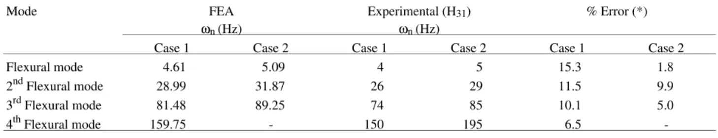
The theoretical damped natural frequencies are shown in Table 4, which shows a better agreement with the experi-mental values than those from undamped frequencies shown previously in Table 2. It is seen a slight reduction of the errors since the damping ratios are smaller in this case. It is expected a larger reduction for the cases where higher damping ratios are presented. Although the improvement obtained in the results are not much significant, they vali-date the proposed procedure to estimate the damping be-havior of composite structures.
4. Conclusions
The theoretical results from FEA (ANSYS®) showed in general a good agreement with the experimental values because the maximum error equal to 16.5% and when the procedure was used this error was reduced to 15.3%. Al-though, this improvement is small, it shows that the pro-posed procedure can be used to evaluate the dynamic analysis of composite structures, mainly when the viscoe-lastic effects of matrix are higher.
Theoretical and experimental results show clearly that changes in the laminate stacking sequences yield to differ-ent dynamic behavior of the compondiffer-ent, that is, differdiffer-ent natural frequencies and damping factors for the same ge-ometry, mass and boundary conditions. In practical appli-cations, it means that if a natural frequency excites the structure, the designer can change the material properties by changing the laminate stacking sequence, instead of re-design the complete structure.
By using the program FREQ, which allows the estima-tion of the damping factors, it is possible to perform a damped dynamic analysis. The results shown in Table 3 demonstrate the coherence of the results from freq. There-fore, engineers can use these results associated with finite element analysis to have an estimation of natural frequen-cies and mode shapes of damped composite structures. As a final remark, the use of finite element analysis associated with experimental procedures can give the designer tools to estimate the dynamic performance of the component, giving the designer the possibility to tailor the dynamic behavior of the component to its requirements.
References
1. Umekawa, S.; Momoshima, S. Composites in Japan. Comp. Eng., v. 2, n. 8, p. 677-690, 1992.
2. He L.; Wang, I.; Tang, D. Dynamic responses of aircraft wing made of composite materials, In: Pro-cedings of IMAC Conference, Kissimme, v. 2, p. 1342-1346, 1993.
3. Eslimy-Isfahay, S.H.R.; Banerjee, J.R. Dynamic re-sponse of composite plates with application to aircraft wings. Journal of Aircraft, v. 34, n. 6, p. 785-791, 1997.
4. Tsai, S.W.; Hanh, H.T. Introduction to Composite Materials. Wesport, Technomic, 1980.
5. Tsai, S.W. Composites Design. Think Composite, Dayton, 1986.
6. Vinson, J.R.; Sierakowski, R.L. Behavior of Struc-tures Composed of Composite Materials. Dordrecht, Martins Nijhoff, 1986.
7. Koo, K.N.; Lee, I. Dynamic behavior of thick com-posite beams. Journal of Reinforced Plastics and Composites, n. 14, p. 196-210, 1995.
8. Khdeir, A.A. Dynamic response of antisymmetric cross-ply laminated composite beams with arbitrary boundary conditions. International Journal Engineer-ing Science, v. 34, n. 1, p. 9-19, 1996.
9. Rao, S.R.; Ganesan, N. Dynamic response of non-uni-form composite beams. Journal of Sound and Vibra-tion, v. 200, n. 5, p. 563-577, 1997.
Table 4. Natural damped frequencies from FEA and experimental test.
Mode FEA
ωn(Hz)
Experimental (H31) ωn(Hz)
% Error (*)
Case 1 Case 2 Case 1 Case 2 Case 1 Case 2
Flexural mode 4.61 5.09 4 5 15.3 1.8
2nd Flexural mode 28.99 31.87 26 29 11.5 9.9
3rd Flexural mode 81.48 89.25 74 85 10.1 5.0
4th Flexural mode 159.75 - 150 195 6.5
-(*) % Er r or=ωFEA− ωExperimental ωExperimental
.
Table 3. Damping factors from experimental results, calculated by pro-gramFREQ.
Modes Case 1 Case 2
ζn ζn
1st Flexural mode 0.063 0.040
2nd Flexural mode 0.048 0.034
3rd Flexural mode 0.020 0.026
-10. Zapfe, J.A.; Lesieutre, G.A. Vibrations analysis of laminated beams using an interative smeared laminate model.Journal of Sound and Vibration, v. 199, n. 2, p. 275-284, 1997.
11. Suarez, S.A.; Gibson, R.F.; Sun, C.T.; Chatuverdi, S.K. The influence of fiber length and fiber orientation on damping and stiffness of polymer composite mate-rials.Experimental Mechanics, v. 26, n. 2, p. 175-184, 1986.
12. Adams, R.D. Damping properties analysis of compos-ites. In: Engineered Materials Handbook, Compos-ites, ASM International, Ohio. Library of Congress Catalogin in Publication Data., v. 1, p. 206-217, 1987. 13. Cudney, H.H.; Inman, D.J. Experimental verification of damping mechanisms in a composite beam. In:
Proceedings of IMAC Conference, Las Vegas, v. 1, p. 704-710, 1989.
14. Greif, R.; Hebert, B. Experimental techniques for dynamic characterization of composite materials. Ad-vances in Experimental Mechanics and Biomimetics
(ASME - 1992), AD-49/AMD-146:83-97.
15. Hwang, S.J.; Gibson, R.F. The use of strain energy based finite element techniques in the analysis of various aspects of damping of composite materials and structures. Journal of Composite Materials, v. 26, v.17, p. 2585-2605, 1992.
16. Adams, R.D.; Bacon, D.G.C. Effect of fiber orienta-tion and laminate geometry on the dynamic properties of CFRP. Journal of Composite Materials, v. 7, p. 402-428, 1973.
17. Lin, D.X.; Ni, R.G.; Adams, R.D. Prediction and measurement of the vibrational damping parameters of carbon and glass fibre-reinforced plastics plates.
Journal of Composite Materials, v. 18, p. 193-199,1984.
18. Zabaras, N.; Pervez, T. Viscous damping approxima-tion of laminated anisotropic composite plates using the finite element method. Computer Methods in Ap-plied Mechanics and Engineering, n. 81, p. 291-316, 1990.
19. Hu, B-G.; Dokainish, M.A. Damped vibrations of laminated composite plates - Modeling and finite ele-ment analysis. Finite Elements in Analysis and De-sign, n. 25, p. 103-124, 1993.
20. Qian, G.; Hoa, S.V.; Xiao, X. A vibration method for measuring mechanical properties of composite, the-ory and experiment. Composite Structures, v. 39, n. 1-2, p. 31-38, 1997.
21. Finegam, I.C.; Gibson, R.F. Improvement of damping at micro mechanical level in polymer composite ma-terials under transverse normal loading by the use of special fiber coatings. Journal of Vibration and Acoustic, n. 120, p. 623-627, 1998.
22. Chandra, R.; Singh, S.P.; Gupta, K. Damping studies in fiber-reinforced composites - a review. Composite Structures, v. 46, n. 1, p. 41-51, 1999.
23. Hull, D. An introduction to composite materials. Lon-don, Cambridge University Press, 1981.
24. Agarwal, B.D.; Broutman, L.J. Analysis and perform-ance of fiber composites. New York, John Wiley & Sons, 1990.
25.Ansys User’s Manual. Theory, Procedures, Elements, 1995; IV.
26. Bathe, K-J. Finite Element Procedures, New Jersey: Prentice-Hall, 1996.
27. Lirani, J. Substructuring techniques in the analysis of partially coated structures. Ph.D. Thesis, Department of Mechanical Engineering, UMIST, The University of Manchester, 1978.
28. Lirani, J. Determinação da estabilidade teórica contra trepidação de máquinas ferramentas com o auxílio de computador. Tese (Livre-Docência), Escola de Engenharia de São Carlos, Universidade de São Paulo, 1985.
29. Baptista, L.H. Uma contribuição para a análise da estabilidade contra trepidação de máquinas ferramen-tas.Dissertação (Mestrado), Escola de Engenharia de São Carlos, Universidade de São Paulo, 1995.