Numerical Modelling of Crack Propagation in Cement PMMA: Comparison of Diferent
Criteria
Abdelkader Boulenouara, Ali Benouisb*, Noureddine Benseddiqc
aMaterials and Reactive Systems Laboratory, Mechanical Engineering Department, Djillali Liabes
University of Sidi Bel-Abbes, Larbi Ben Mhidi City, Algeria
bMechanics and Physics of Materials Laboratory, Mechanical Engineering Department, Djillali Liabes
University of Sidi Bel-Abbes, Larbi Ben Mhidi City, Algeria
cMechanics Laboratory of Lille, Ecole Polytech’Lille, University of Lille, 59655, Villeneuve d’Ascq,
France
Received: December 23, 2015; Revised: May 9, 2016; Accepted: June 5, 2016
Modelling of a crack propagating through a inite element mesh under mixed mode conditions is of prime importance in fracture mechanics. In this paper, three diferent crack growth criteria and the respective crack paths prediction in the cement mantle of the reconstructed acetabulum are compared. The maximum tangential stress (MTS) criterion, the minimum strain energy density (MSED) criterion and the new general fracture criterion based on the energy release rate G(θ) are investigated using advanced inite element technique. The displacement extrapolation technique (DET) is used, to obtain the SIFs at crack tip. Several examples are presented to show the robustness of the numerical techniques. The efect of the inclusions and cavities on the crack propagation in cement orthopedic are highlighted.
Keywords: Crack growth path, Stress intensity factor, Maximum tangential, Strain energy density, Maximum energy release
1. Introduction
Total Hip Replacement (THR) is one of the most successful surgical procedures ever developed where a ball-socket structure is used to replace a diseased or damaged hip joint. The replacement cup socket is usually attached to the pelvis by acrylic bone cement, which consists of polymethylmethacrylate (PMMA) powder and a liquid component of methylmethacrylate monomer (MMA). When mixing together, polymerization takes place and within a few minutes (10-20 minutes depending on the formulation) of application to the bone cavity, the mixture becomes solid1,2.
Figure 1 show a schematic of a cemented THR where the acetabular cup is ixed by the cement to the pelvic bone. The stability of the ixation critically depends on the integrity of the bone cement under typical physiological loading conditions. At least one million loading cycles per year would be experienced by the hip joint with the maximum hip contact force up to three times of body weight during walking3.
The presence of defects in the cement during mixing can locally lead to regions of stress concentrations producing a possible fracture of the cement and consequently loosening of the prosthetic cup. There are three major types of defects4:
porosities, inclusions and cracks.
It is known that cracks are the most dangerous type of defect because of the presence of stress intensity on their front. Most cracks identiied in orthopedic cement are5:
• Cracks initiated at porosities (Figure 2). • Cracks initiated during cement withdraw. • Cracks initiated at the junction between bone and
cement or between cement and cup.
In the literature, there has been a little research carried out into the crack’s growth path in the orthopedic cement, there have been some studies dealing with the fatigue life and/or fracture of orthopedic cement, but not following the crack’s growth path6,7,8,9. Benbarek
et al.10 used the finite element method to analyze the
propagation path of the crack in orthopedic cement around a total hip replacement. Results show that the crack propagation’s path can be influenced by human body posture. Benouis et al.11 presented a numerical
modeling of crack propagation trajectory in cement of reconstructed acetabulum. The direction crack is evaluated as a function of the displacement extrapolation technique and the strain energy density theory. Kim et al.12 determine the specific fracture mechanics response
of cracks that initiate at the stem-cement interface and propagate into the cement mantle.
For a crack under the mixed-mode I/II loading conditions, a number of fracture criteria have been developed through a concerted effort by many researchers in the past decades. Erdogan et al.13 proposed the
maximum circumferential stress (MCS) criterion, which assumed that fracture occurs in the direction where the circumferential stress surrounding the crack tip is the maximum. Smith et al.14 developed a generalized
maximum tensile stress criterion by taking T-stress into consideration. Alternatively, the minimum strain energy density (MSED) criterion introduced by Sih15
assumed that fracture occurs in the direction where the strain energy density is the minimum. Hussain et al.16, Palaniswamy and Knauss17, Nuismer18 and Wu19
proposed the maximum energy release rate (MERR) criterion based on Griffith’s theory20, 21 proposed a new
Figure 1: A schematic of a cemented acetabular replacement in a total hip replacement22,23.
Figure 2: Cracks in acrylic bone cement observed under transmitted light24,25.
general mixed-mode brittle fracture criterion based on the concept of maximum potential energy release rate (MPERR).
This paper presents a inite element analysis for the modeling of the crack growth problems in cement of reconstructed acetabulum using the displacement extrapolation technique (DET). This modeling is based on the maximum tangential stress criterion (MTS), the minimum strain energy density (MSED) criterion and the general fracture criterion based on the approximate expression of energy release rate G(θ), to present a comparison of the crack propagation paths. In this investigation, the efect of the inclusions and cavities on the crack trajectories in cement orthopedic was examined.
2. Crack Growth Criteria
In order to simulate crack propagation under linear elastic condition, the crack path direction must be determined. There are several methods used to predict the direction of crack trajectory such as the maximum tangential stress theory (or the maximum circumferential stress theory)13, the minimum
strain energy density theory15 and the maximum energy
release rate criterion based on Griith’s theory20.
2.1. MTS criterion
Erdogan et al.13 were the irst to propose a crack initiation
criterion using stress as a critical parameter. This criterion states that direction of crack initiation coincides with the direction of the maximum tangential stress along a constant radius around the crack tip so it is called the maximum tangential stress (MTS) criterion. It can be stated mathematically as26:
0
0
1
2 22
2
2
2
1
i
vi
i
vi
=
] g
Z
[
\
]]
]]
]]
]]
( )
tan
2i
2
-
n
2
tan
i
2
-
2
1
=
0
2
( )
cos
cos
sin
sin
sin
cos
2
3
2
1
2
2
2
1
2
2
7
2
2
0
3
3 2
3 3
1
i
i
i
n
i
i
i
--
+
-b
b
l
l
R
T
SS
SS
SS
SS
S
V
X
WW
WW
WW
WW
W
Where KKII I
n=
Where: KI and KII are respectively the SIFs corresponding
to mode I and mode II loading. Eq. (2) can be solved for θ such that θ= θ0, which is the predicted crack initiation angle.
2.2. MSED criterion
Sih27 used strain as a critical parameter in order to propose
the minimum strain energy density (MSED) criterion. It states that the direction of crack initiation coincides with the direction of minimum strain energy density along a constant radius around the crack tip. The MSED criterion showed a good agreement with the experimental results obtained earlier by Erdogan et al.13. In addition, this criterion is the
only one that shows the dependence of the initiation angle on material property represented by Poisson’s ratio ν. In mathematical form, this approach can be stated as:
s
s
0
0
4
2 22
2
2
2
1
i
i
=
] g
Z
[
\
]]
]]
]]
]]
Where S is the strain energy density factor, deined as:
( )
Where is the strain energy density function per unit volume, and r0 is a inite distance from the point of failure initiation. The angle of crack propagation θ can be determined by solving the following equations26:
( )
tan
tan
tan
tan
k
k
k
k
2 1
2
2 1
2
2
10
2
24
2
2 1
6
14
2
2 3
0
6
4 2 2
3 2 2 2
n
i
n
n
i
n
i
n
n
i
n
+
+
-
-
+
-
+
-
+
-+
-
=
]
]
^
^
g
g
h
h
6
6
6
@
@
@
0
( )
sin
sin
cos
cos
k
k
2
1
8
2
1 1
2
3
2
7
2 2
1
n
i
n
i
n
i
n
i
-
-
+
-
-
+
-]
]
^
^
g
g
h
h
6
6
@
@
6
@
2.3. G(θ) criterion
In order to predict the fracture direction of cracked materials under the general mixed-mode state, Chang et al.21
presented a new general mixed-mode brittle fracture criterion based on the concept of maximum potential energy release rate (MPERR). This criterion can be easily degraded to the pure mode fracture criterion, and can also be reduced to the commonly accepted fracture criteria for the mixed-mode I/ II state. The criterion can be described as:
( )
G
G
0
0
8
2 22
2
2
2
1
i
i
i
i
=
]
]
g
g
Z
[
\
]]
]]]
]]
]]]
G(θ) is the energy release rate in θ direction, can be expressed as21:
( )
cos
cos
sin
cos
G
k
K
K K
K
2
1
2
8
1
1
4
5
9
I I II II 2 2 2i
n
i
i
i
i
=
+
+
+
-]
]
]
g
g
g
R
T
SS
SS
SS
SSS
V
X
WW
WW
WW
WWW
Z
[
\
]]
]]]
]]
]]
_
a
bb
bbb
bb
bb
3. Numerical Calculation of Stress Intensity
Factors
Fracture mechanics is based on the determination of stress intensity factors. It is therefore important to develop a numerical model capable of calculating these factors for diferent geometries of cracked structures under diferent boundary conditions. In this paper, the displacement extrapolation method28, 29 is used to calculate the stress
intensity factors KI and KII as follows:
,
( )
K
v
k
E
L
v
v
v
v
3 1
1
2
4
2
10
I b d c e
r
=
+
+
-
-
-]
]
]
]
g
g
g
g
;
E
, ( )
K
v
k
E
L
u
u
u
u
3 1
1
2
4
2
11
II b d c e
r
=
+
+
-
-
-]
]
]
]
g
g
g
g
;
E
Where k=3-4n for plane strain and k= (3-n)/(1+n) for plane stress. L is the length of the element side connected to the crack tip.
uiand vi(i=b, c, d and e) are the nodal displacements
at nodes b, c, d and e in the x and y directions, respectively (Figure 3).
Figure 3: Special elements used for displacement extrapolation method.
In order to obtain a better approximation of the ield near the crack tip, special quarter point inite elements proposed by Barsoum30 are used where the mid-side node of the element
in the crack tip is moved to 1/4 of the length of the element L.
4. Methodology of Crack Modeling
In this paper, the APDL code has been employed to create the program to simulate the mixed-mode crack propagation in the cement. The displacement extrapolation technique is used, to determine the SIFs at each increment of the crack length.
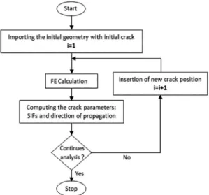
The crack propagation is characterized by successive propagation steps performed without user interaction. Each step consists of:
1. Setting the geometrical with initial crack and input material properties data of the problem.
2. Discretization of the model by plane2 elements. 3. Mesh generation; reining around the crack-tip. 4. FE analysis.
5. Calculation of SIFs.
6. Calculation of crack propagation direction using the criteria proposed in this investigation. 7. Crack arrests? If yes, go to step 8. If no, go to step 9. 8. Stop.
10. Return to Step 3: The algorithm is repeated until ultimate failure of material or by using another criterion for termination of the simulation process. Figure 4 shows the Flow-chart of the prepared APDL code based on the combination of the inite element analysis and the crack growth criteria.
a circular surface that was mated with congruent spherical acetabular socket. The mechanical properties of cement, cup and all subregions of the acetabulum bone are given in Table 1.
Figure 4: A lowchart of the main operations which make the crack propagation
5. Geometric, Material’s Deinition and
Loading Conditions
The model was generated from a roentgenogram of a 4mm slice normal to the acetabulum through the pubic symphysis and ilium. The inner diameter of the UHMWPE cup was 54mm and the cement thickness was taken as 2mm24, 25. Figure 5a shows the geometrical model used in
this investigation. The initial crack of length of a= 50μm
emanating from the interface cup/cement is presumed to exist in the cement layer (Figure 5b).
Figure 5. a) Geometrical model, b) Initial crack emanating from interface cup/cemet.
The model was divided into seven regions (Figure 5a) of diferent elastic constants with isotropic material properties assumed in each region. The femoral head was modelled as
Table 1: Materials' properties31,32.
Materials Young’s modulus E (MPa) Poisson’s ratio (ν) Cortical bone 17000 0.30
Sub-chondral bone 2000 0.30
Spongious bone 2 70 0.20
Spongious bone 3 2 0.20
Cup (UHMWPE) 690 0.35
Cement (PMMA) 2300 0.30
Metallic implant 210000 0.30
In order to approach the reality, force F=2400N is applied to the centre of the femoral head (Figure 6). It corresponds to a three times of average weight of man (80kg) 5. These
conditions of loading are considered as the extreme case of an efort which the prosthesis can support. It is the force which man can exert on only one support at time of rise of staircase33. The loading cases analysed in this study correspond
to 0° of the metallic implant position.
Figure 6: Boundary conditions (0° of the metallic implant position).
Figure 6 shows boundary conditions acting on the model. To simulate the connections with the remainder of the basin, we blocked the nodes corresponding to the junction with the iliac bone34. The boundary conditions imposed on the
geometrical model are taken from previous work10,11,32,35,36. ux and uy indicate the displacements in the x and y
directions, respectively.
6. Finite Element Model
The Finite element standard code ANSYS37 has been
is shown in Figure 7a. The special quarter point singular elements proposed by Barsoum30 are investigated for modeling
the singular ield near the crack tip in cement layer (Figure 7b). For a=50μm, the mesh discretization consists of 66583
elements and 136529 nodes. The numerical simulation is performed in plane stress conditions.
Figure 7: (a) Mesh model and (b) Special elements used for DET.
7. Results and Analysis
7.1. Evolution of SIFs
In order to simulate the behavior of a crack under mixed mode loading (mode I+II); we considered an example of a crack of length a localized in the cement layer. This crack is inclined to the horizontal x-axis from -35° to 90°.
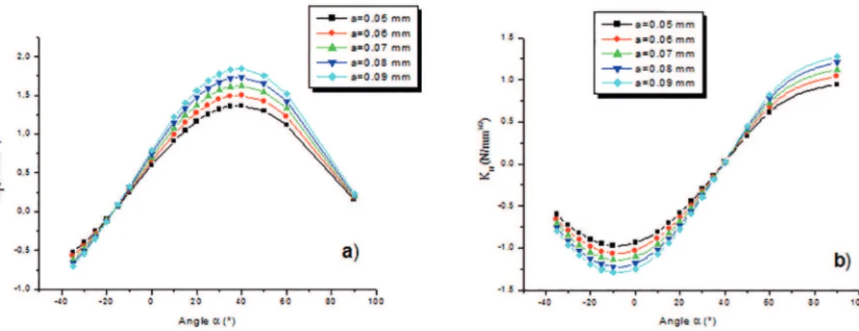
Figures 8a and 8b show, respectively, the variations of the SIFs KI and KII according to the crack inclination α, for
various crack length. The results obtained show that: 1. The SIF KI is maximum when the angle α=40°
(Figure 8a), then it decreases gradually with the increase of the positive angle and tends to a very low value as one approaches the interface cup/cement. 2. The SIF KI decreases with the angle α, up to a
minimal value corresponds to an angle α=-18° from which factor KItakes values negative with
the decrease of the angle α. These negative values of KI indicate that the crack lips are closed due to stress compression around the crack tip.
3. The SIF KII is null when the inclination angle
α=40° and increases with this angle (Figure 8b). The factor KII decreases with the angle α up to a
minimal value corresponds to an angle α≈-18° from
Figure 8: Variation of SIFs vs. crack length a and crack inclinaison α: a) KI evolution and b) KII evolution.
which the curve takes on a downward look with the decrease of angle α.
Through these results, we can conclude that the initial crack angle of 40° represents the initial direction of the crack propagation according to the opening mode (mode-I) with:
KI=KImax and KII=0.
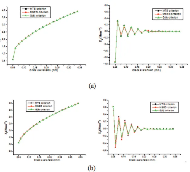
Figure 9 shows the evolution of SIFs KI and KII during crack propagation extension obtained by MTS criterion. These results are compared with those obtained by MSED and G(θ) criterion. The plotted curves show a good agreement
between these three approaches.
A good correlation between these criterion are veriied for another initial crack direction (α=0° and 60°). The crack paths obtained are shows in Figure 10.
7.2. Crack propagation simulation
The values of SIFs are used to determine in Figure 11, the inal crack path by calculating the crack propagation direction at each time step. The three crack trajectories are obtained for initial crack propagation α=0°. This comparison shows a good correlation between the three simulations.
In order to determine the efect of a geometry defect on the crack propagation, we chose a circular cavity of radius r
= 100 μm located in cement layer, at a vertical distance y =
0.25mm from the crack tip. Foucat34 found that the size of
the cavities existing in the cement is between a few micro-millimeters to 1 mm. The geometrical model is meshed by triangular elements in cement layer and by special quarter point singular elements around the crack-tip (Figure 12).
Figure 13 presents three steps of crack propagation path using the GF criterion. We ind that the crack is moving towards the cavity. This is because the cavity creates a stress drop that will change the maximum principal stress in the cement layer and draw the crack. Once the cavity has passed, this crack shifts under mode-I loading, and it departs slightly from the cavity. The comments we get correspond with those obtained by Benouis et al.11 and by Boulenouar
et al.36 to study the crack growth path in the cement mantle
using MSED criterion.
Figure 9: Variation of SIFs during crack extension for α=40°: a) KI evolution and b) KII evolution.
Figure 10: Variation of SIF KI and KII during crack extension for a) α=0° and b) α=60.
a default, respectively. The crack trajectories obtained by MTS and GF criteria are compared with the results obtained by Benouis et al.11, using the MSED approach. The three
criteria give good results on the crack propagation path and the results between them are very close. This behavior of
crack propagation conirms the comments obtained in the case of a cracked path with a hole 38, 39,40. Without a defect,
Figure 11: Crack trajectories comparison.
Figure 12: Typical mesh model near the cavity and the crack.
Figure 13: Three steps of crack propagation predicted by GF criterion (Cavity efect).
Figure 14: Crack trajectories comparison: a) without defect and b) with defect.
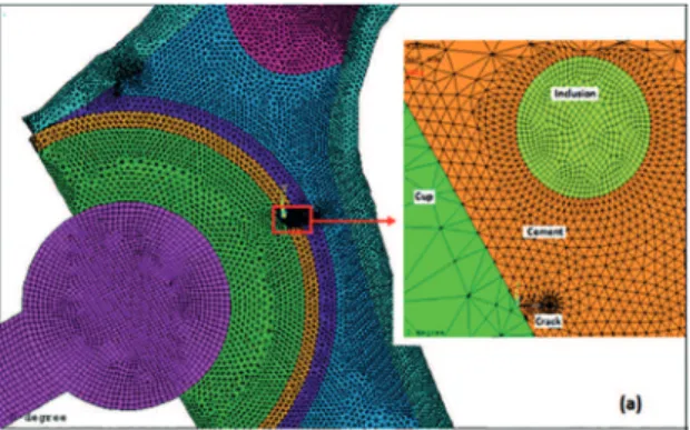
In what follows, we propose to studied the crack propagation in our model containing an inclusion of radius
r = 100 μm. Figure 15 shows the typical mesh model near
the inclusion and the crack. We recall that the mechanical properties of the cement are: Young’s modulus E1=2300 MPa and Poisson’s ratio ν1=0.3 and the inclusion considered is characterized by its Young’s modulus E2 and Poisson’s
ratio ν2=ν1.
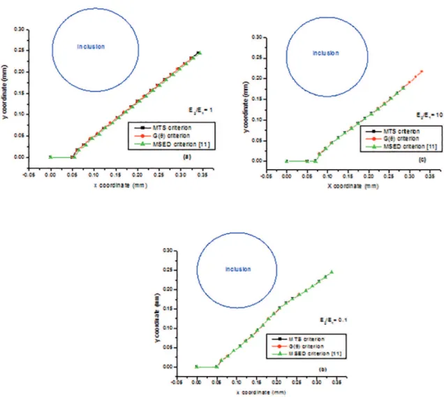
To demonstrate the inclusion efect on the propagation path, we evaluated for three ratios E2/E1 = 1, 0.1 and 10, the SIFs and the crack direction for each increment Δa to predict then the propagation path using MTS approach. Figure 16 show respectively the steps of crack trajectory for three ratios E2/E1= 1, 0.1 and 10. A calculation made by our integrated model shows that:
a) When the matrix (cement layer) and inclusion have the same mechanical properties (E2/E1=1),
the crack is propagated in its possible direction as a single homogeneous material (Figure 16 a).
b) In the case of the inclusion less rigid than the matrix (E2/E1=0.1), we ind a result similar to that which
had been obtained for the cracked cement with a cavity (see Figure 14b); this inclusion changes the stress distribution and attracts the crack. Once the inclusion exceeded the crack in its possible direction (Figure 16b).
c) In the case of the inclusion is more rigid than the cement (E2/E1=10), the crack is this time slightly
Figure 15: Typical mesh model near the inclusion and the crack.
Figure 16: Inclusion efect on the propagation path (MTS criterion) with: a) E2/E1= 1, b) E2/E1= 0.1, c) E2/E1= 10.
Figure 17: Inclusion efect on the crack propagation path predicted by: a) MTS criterion, b) G(θ) criterion, b) MSED criterion11,36. Figure 17 shows the efect of inclusion on the inal crack trajectories obtained by MTS and GF criteria (with E2/E1
= 1, 0.1 and 10). Practically, the selected criteria give the same behavior of crack propagation explained for Fig. 16, using criterion MTS.
For better presenting the comparison between the crack path obtained by the three criteria, Figure 18 illustrates the inal crack trajectories predicted by MTS and GF criteria, for each ratio E2/E1. Under the same loading conditions, these results are compared with the results obtained in reference11,36, using the MSED theory. This comparison
Figure 18: Crack trajectories comparison a) E2/E1= 1, b) E2/E1= 0.1, c) E2/E1= 10
8. Conclusion
In this paper, three crack kinking criteria and the crack paths prediction for several cases are compared in a PMMA cement layer. The maximum tangential stress criterion, the strain energy density criterion and the general fracture criterion are investigated using advanced inite element techniques. In order to obtain a better approximation of the ield near the crack tip in cement of reconstructed acetabulum, special quarter point inite elements proposed by Barsoum are used. The displacement extrapolation technique is investigated to determine the SIFs under mixed-mode loading. Numerical calculations made by the inite element method show that this technique can correctly describe the stress and deformations ield near the crack tip.
The initial crack angle of 40° represents the initial direction of the crack propagation according to the opening mode.
The three criteria give good results on the crack propagation path and the results between them are very close, for the cases proposed in this study.
The implementation of 2D crack propagation process in FE code can account for the inluence of inclusions on the path of crack propagation in cement layer. This feature can be very interesting for propagation in multilayered or in composite parts.
Conlict of Interests
The authors declare that there is no conlict of interests regarding the publication of this paper.
9. References
1. Bouziane MM, Bachir Bouiadjra B, Benbarek S, Tabeti MSH, Achour T. Finite element analysis of the behaviour
of microvoids in the cement mantle of cemented hip
stem: Static and dynamic analysis. Materials and Design.
2010;31(1):545-550.
2. Achour T, Tabeti MSH, Bouziane MM, Benbarek S, Bachir Bouiadjra B, Mankour A. Finite element analysis of interfacial
crack behavior in cemented total hip arthroplasty. Computational Materials Science. 2010;47(3):672-677.
3. Tong J, Wong KY. Mixed Mode Fracture in Reconstructed
Acetabulum. In: Proceedings of 11th International Conference on Fracture; 2005 Mar 20-25; Turin, Italy.
4. Benbarek S, Bachir Bouiadjra B, Mankour A, Achour T, Serier
B. Analysis of fracture behaviour of the cement mantle of reconstructed acetabulum. Computational Materials Science.
5. Bachir Bouiadjra B, Belarbi A, Benbarek S, Achour T, Serier B. FE analysis of the behaviour of microcracks in the cement
mantle of reconstructed acetabulum in the total hip prosthesis. Computational Materials Science. 2007;40(4):485-491.
6. Ramos A, Simões JA. The inluence of cement mantle thickness and stem geometry on fatigue damage in two different
cemented hip femoral prostheses. Journal of Biomechanics.
2009;42(15):2602-2610.
7. Graham J, Pruitt L, Ries M, Gundiah N. Fracture and fatigue
properties of acrylic bone cement: The efects of mixing method,
sterilization treatment, and molecular weight. The Journal of Arthroplasty. 2000;15(8):1028-1035.
8. Lennon AB, McCormack BAO, Prendergast PJ. The relationship between cement fatigue damage and implant surface inish in proximal femoral prostheses. Medical Engineering & Physics;2004;25(10):833-841.
9. Jefers JRT, Browne M, Lennon AB, Prendergast PJ, Taylor
M. Cement mantle fatigue failure in total hip replacement:
Experimental and computational testing. Journal of Biomechanics.
2007;40(7):1525-1533.
10. Benbarek S, Bachir Bouiadjra B, Bouziane MM, Achour T, Serier B. Numerical analysis of the crack growth path in the
cement mantle of the reconstructed acetabulum. Materials Science and Engineering: C. 2013;33(1):543-549.
11. Benouis A, Boulenouar A, Benseddiq N, Serier B. Numerical analysis of crack propagation in cement PMMA: application of SED approach. Structural Engineering and Mechanics.
2015;55(1):93-109.
12. Kim B, Moon B, Mann KA, Kim H, Boo KS. Simulated crack
propagation in cemented total hip replacements. Materials Science and Engineering: A. 2008;483-484:306-308.
13. Erdogan F, Sih GC. On the crack extension in plates under plane
loading and transverse shear. Journal of Basic Engineering.
1963;85(4):519-525.
14. Smith DJ, Ayatollahi MR, Pavier MJ. The role of T-stress in
brittle fracture for linear elastic materials under mixed-mode
loading. Fatigue & Fracture of Engineering Materials & Structures. 2001;24(2):137-50.
15. Sih GC. Some basic problems in fracture mechanics and new
concepts. Engineering Fracture Mechanics. 1973;5(2):365-377.
16. Hussain MA, Pu SL, Underwood J. Strain energy release rate for a crack under combined mode I and mode II. In: Paris PC, Irwin GR, eds. Fracture analysis. Philadelphia: American
Society for Testing and Materials; 1974. p.2-28.
17. Palaniswamy K, Knauss WG. On the problem of crack extension in brittle solids under general loading. In: Nemat-Nasser S,
ed. Mechanics today. vol. 4. New York: Pergamon Press;
1978. p.87-148.
18. Nuismer RJ. An energy release rate criterion for mixed mode
fracture. International Journal of Fracture. 1975;11(2):245-50.
19. Wu CH. Fracture under combined loads by maximum-energy-release-rate criterion. Journal of Applied Mechanics.
1978;45(3):553-8.
20. Griith AA. The phenomena of rupture and low in solids.
Philosophical Transactions of the Royal Society of London. Series A. 1921;A221(582-593):163-198.
21. Chang J, Xu JQ, Mutoh Y. A general mixed-mode brittle fracture
criterion for cracked materials. Engineering Fracture Mechanics.
2006;73(9):1249-1263.
22. Benbarek S, Sahli A, Bouziane MM, Bachir Bouiadjra B, Serier
B. Crack length estimation from the damage modelisation around a cavityi in the orthopedic cement of the total hip prosthesis. Key Engineering Materials. 2014;577-578:345-348.
23. Sahli A, Benbarek S, Bouiadjra B, Mokhtar BM. Efects of Interaction between Two Cavities on the Bone Cement Damage of the Total Hip Prothesis. Mechanics and Mechanical Engineering. 2014;18(2):107-120.
24. Benbarek S, Bachir Bouiadjra B, Mankour A, Achour T, Serier
B. Analysis of fracture behaviour of the cement mantle of reconstructed acetabulum. Computational Materials Science.
2009;44(4):1291-1295.
25. Benbarek S, Bachir Bouiadjra B, Achour T, Belhouari M, Serier B. Finite element analysis of the behaviour of crack emanating
from microvoid in cement of reconstructed acetabulum. Materials Science and Engineering: A. 2007;457(1-2):385-391.
26. Bhadauria BB, Pathak KK, Hora MS. Finite element modeling of crack initiation angle under mixed mode (I/II) fracture.
Journal of Solid Mechanics. 2010;2(3):231-247.
27. Sih GC. Strain-energy-density factor applied to mixed-mode crack
problems. International Journal of Fracture. 1974;10(3):305-321.
28. Alshoaibi AM, Hadi MSA, Ariin AK. An adaptive inite element
procedure for crack propagation analysis. Journal of Zhejiang University SCIENCE A. 2007;8(2):228-236.
29. Boulenouar A, Benseddiq N, Mazari M. Strain energy density
prediction of crack propagation for 2D linear elastic materials. Theoretical and Applied Fracture Mechanics. 2013;67-68:29-37.
30. Barsoum RS. On the use of isoparametric inite element in
linear fracture mechanics. International Journal for Numerical Methods in Engineering. 1976;10(1):25-37.
31. Ouinas D, Flliti A, Sahnoun M, Benbarek S, Taghezout N. Fracture
Behavior of the Cement Mantle of Reconstructed Acetabulum
in the Presence of a Microcrack Emanating from a Microvoid.
International Journal of Materials Engineering. 2012;2(6):90-104.
32. Zouambi L, Serier B, Fekirini H, Bouiadjra B. Efect of the Cavity-Cavity Interaction on the Stress Amplitude in Orthopedic Cement.
Journal of Biomaterials and Nanobiotechnology. 2013,4(1):30-36. 33. Leroy R. Etude et comportement non-uniforme de l’interface
entre implant fémoral et liant polymérique dans le cas de prothèses totales de hanche cimentées. [Thèse de doctorat].
Tours: Universit́ Fraņois Rabelais; 1997.
34. Foucat D. Efets de la présence d’un grillage métallique au sein du ciment de scellement des cupules des prothèses totales de hanche. Etude mécanique et thermique. [Thèse de doctorat].
Strasbourg: Universit́ Louis Pasteur; 2003.
35. Benouis A. Efet d’interactión des cavités sur le comportement du cément orthopédique de prothèse totale de hanche. [Thèse
de doctorat]. Sidi-Bel-Abbès: Universit́ Djillali Liabes; 2015. 36. Boulenouar A, Benouis A, Merzoug M. Application of strain
energy density approach in biomechanics fracture problems. In: Actes de la 2ème Conférence Internationale de Mécanique
(ICM’15); 2015 Nov 25-26; Constantine, Algeria.
37. ANSYS. Programmer’s Manual for Mechanical APDL, Release 12.1; 2009. [cited 2016 Jun 16]. Available from: http://www.pdfdrive. net/programmers-manual-for-mechanical-apdl-e10865820.html 38. Bouchard PO, Bay F, Chastel Y. Numerical modelling of crack
propagation: automatic remeshing and comparison of diferent
criteria. Computer Methods in Applied Mechanics and Engineering.
2003;192(35-36):3887-3908.
39. Boulenouar A, Benseddiq N, Mazari M. Two-dimensional Numerical Estimation of Stress Intensity Factors and Crack Propagation in Linear Elastic Analysis. Engineering, Technology & Applied Science Research. 2013;3(5):506-510.
40. Boulenouar A, Benseddiq N, Mazari M, Benamara N. FE model for linear-elastic mixed mode loading: estimation of SIFs