M. Ševčík et al, Frattura ed Integrità Strutturale, 34 (2015) 216-225; DOI: 10.3221/IGF-ESIS.34.23
216
Focussed on Crack Paths
Analytical model of asymmetrical Mixed-Mode Bending
test of adhesively bonded GFRP joint
M. Šev
č
ík, P. Huta
ř
Institute of Physics of Materials, Academy of Sciences of the Czech Republic, v. v. i., Žižkova 22, 616 62 Brno, Czech Republic [email protected]; [email protected]
A. P. Vassilopoulos
Composite Construction Laboratory CCLab, Ecole Polytechnique Fédérale de Lausanne EPFL, Station 16, CH-1015 Lausanne, Switzerland
M. Shahverdi
Structural Engineering Research Laboratory, Empa, Swiss Federal Laboratories for Materials Science and Technology, Überlandstrasse 129, 8600 Dübendorf, Switzerland
ABSTRACT. This paper presents new analytical model of asymmetric mixed-mode bending (MMB) specimen of adhesively bonded pultruded GFRP joints. An easily applicable relationship for the calculation of the strain energy release rate of the asymmetric MMB specimens is proposed based on the beam theory. The model is capable to analyze stacking sequence as well as various crack propagation paths. In the paper the effect of the various fiber bridging length and different crack propagation paths is analyzed analytically and supported by experimental results. The methodology and results presented in this paper could be utilized for the design of both joint geometry and lay-up of the laminates constituting the joint or for the prediction of the fracture behavior of such structures.
KEYWORDS. GFRP materials; Mixed-Mode bending; Fiber bridging; Analytical model.
INTRODUCTION
iber reinforced polymers are modern kind of materials that benefit from their high stiffness vs. weight ratio. Composite materials are being widely used for aeronautical and space applications for decades. Despite theirs higher initial price these materials can be used also in the civil engineering applications. Material of fibers strongly influences the overall strength of the fiber reinforced polymer materials. Glass or aramid fibers are usually used for the civil applications [1] whereas carbon fibers are used mostly for aerospace and automotive applications [2].
M. Ševčík et al, Frattura ed Integrità Strutturale, 34 (2015) 216-225; DOI: 10.3221/IGF-ESIS.34.23
217
1 mm in the civil engineering application the adhesive layer thickness can reach up to a few centimeters. This nonnegligible adhesive thickness behaves like additional layer in the adhesive joint and should be taken into account when designing the joint against failure.
The main failure mode of the composite materials is delamination of the layers under bending or tension loading and buckling under compression loading [3]. If the crack propagates in the material interface of different materials the crack tip stress field is inherently under mixed-mode behavior [4]. This in fact brings some difficulties for the fracture mechanics analysis of the fiber reinforced polymer materials.
The delamination behavior of adhesively bonded GFRP joints is usually studied by variety of specimens - Double-Cantilever-Beam (DCB) specimen for pure mode I, End-Loaded-Split (ELS) or End Notched-Flexure (ENF) specimen for pure mode II and Mixed-Mode Bending (MMB) for mixed modes tests. Nowadays, the MMB test is one of the standardized test method for evaluation of the interlaminar fracture toughness of unidirectional fiber reinforced polymer matrix composites [5].
The concept of the strain energy release rate (SERR) is commonly used for the fracture mechanics description of the failure behavior of adhesively bonded GFRP laminates [6,7]. There exist various expressions for the calculation of the total strain energy release rate for the symmetric MMB specimens but mostly valid only for symmetrical specimens [8]. The asymmetrical specimens are, however, often accompanied by relatively thick adhesive layer or asymmetry of the stacking sequence either in the laminate or in the adhesive joint and therefore there is a need for the development of the new procedures for the calculation of the strain energy release rate components. Another way is to describe the delamination behavior using the complex stress intensity factor introduced in [4,9].
In this work the concept of the strain energy release rate as a fracture parameter is utilized. For the accurate description of the crack behavior in asymmetric joints it is necessary to decompose the mode components and explicitly estimate their contribution to the total fracture energy [10–12]. Various procedures exist in the literature for the mode separation. Most of them are based on the differences between moments [6], displacements [13] or bending stiffnesses [14] of the two arms of the joint. However, the differences between moments or displacements are applicable only for symmetric specimens. The mode separation based on the difference in bending stiffness of the two arms is applicable for the asymmetric specimens, nevertheless, the bending stiffnesses are usually measured on the cracked specimen and it is therefore difficult to predict the behavior of the joint before the test.
This paper presents new easily applicable relationship for the calculation of the strain energy release rate of the asymmetric MMB specimens that is proposed based on the beam theory and its ability is validated through comparison with experimental results.
MATERIALS DESRIPTION OF THE MMB SPECIMEN
he pultruded GFRP laminates, supplied by Fiberline A/S, Denmark, consisted of E-glass fibers and isophthalic polyester resin. The laminates with 6 mm in thickness consisted of a thin polyester veil in the outer surfaces, two combined mat layers on each side and a roving layer in the middle. Each mat layer comprised of 0/90 woven fabric stitched to a chopped strand material. The fiber architecture of the laminate is schematically shown in Fig. 1. Based on burn-off test, according to ASTM D3171-11 [15] and fiber density of 2560 kg/m3, the fiber content was 43.3 vol. %. A two-component epoxy adhesive system Sikadur 330, Sika AG, Switzerland, was used for the bonding of the GFRP
Figure 1: Scheme and micrograph of the laminate architecture.
Figure 2: Scheme of the mixed-mode bending test.
M. Ševčík et al, Frattura ed Integrità Strutturale, 34 (2015) 216-225; DOI: 10.3221/IGF-ESIS.34.23
218
laminates. The polyester resin (matrix) as well as glass fibers exhibit linear elastic behavior in tension up to brittle fracture [16], therefore, allowing the use linear elastic fracture mechanics for the analysis of the results. All the layers of the laminates were modeled according to the thicknesses estimated by the optical microscopy photos. The material properties and thicknesses of all layers of the laminate as well as the adhesive are listed in the Tab. 1.
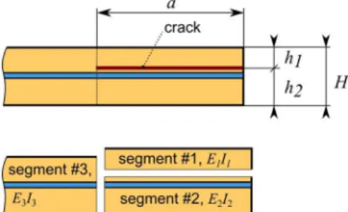
One of the failure mechanisms of the adhesively bonded GFRP pultruded laminates is the delamination cracking. The delamination usually occurs between 1st and 2nd combined mat. For the purpose of this paper four crack propagation paths are distinguished for the used laminate:
Path 0 crack propagation in the middle of adhesive layer
Path I crack propagation between adhesive and 1st combined mat layer
Path II crack propagation between 1st combined mat and 2nd combined mat layer Path III crack propagation between 2nd combined mat layer and roving layer.
Path 0 represent symmetrical MMB specimen whereas Path I, II and III represent increasing level of asymmetry.
layer thickness [mm] E11 [GPa] E33[GPa] 13 [-] G13 [GPa]
veil 0.05 3.2 3.2 0.38 1.2
1st combined mat 0.63 12.8 3.2 0.36 1.4
2nd combined mat 1.07 15.1 3.2 0.36 1.4
roving 2.5 38.9 3.2 0.35 2.7
adhesive 2 4.6 4.6 0.37 1.7
Table 1: Material properties and thicknesses of all layers of the laminate and adhesive [17].
ANALYTICAL MODEL OF MMB TEST
here exists analytical expression for the calculation of the total strain energy release rate of the symmetrical MMB specimen derived by Reeder and Crews in [18,19] in the following form:
2 2
11 2 3 2
2 2
3 3
4 16
3
L c L c E L h b
P a
G (1)
This model has been successfully applied for the adhesively bonded laminate joins where the thickness of the adhesive layer was negligibly thin. However, for the structural applications the adhesive layer varies from millimeters to centimeters and therefore the adhesive layer induces asymmetric geometrical configuration and therefore the analytical model for asymmetrical MMB specimen has to be developed. Even though the Eq. (1) does not take the nonlinear effects (such as rotations of the arms or shear effects) into account it can serve as the reference equation for comparison with the proposed model derived later in this chapter.
To derive the total strain energy release rate for the asymmetric MMB specimen following relation can be used [20]:
a C
b P Gtot
d d 2
2
(2)
where P is the loading force, a is the crack length and C is the compliance of the specimen (C = /P, where is the displacement of the lever below the applied force P). The displacement of the lever can be calculated using Castigliano’s theorem as follows:
P W
(3)
where W is total strain energy. To calculate the strain energy Maxwell-Mohr variant of Castigliano’s theorem can be used in general form:
M. Ševčík et al, Frattura ed Integrità Strutturale, 34 (2015) 216-225; DOI: 10.3221/IGF-ESIS.34.23 219
dx EI M W o 2 2 1 (4)where Mo is bending moment in the segment, EI is bending stiffness of the segment. The MMB specimen can be virtually
divided into three segments, see Fig. 3.
Figure 3: Virtual division of the MMB specimen into three segments.
Figure 4:Scheme of location of forces Pu and Pd.
Each of these three segments has specific bending stiffness that corresponds to the stacking sequence of the segment. For the MMB specimen the strain energy stored in the system can be calculated as follows.
L L d d L a d a u d a u dx I E L x P x P dx I E x P dx I E x P P dx I E x P W 2 4 3 3 2 4 4 3 3 3 2 3 0 2 2 2 2 2 0 1 1 1 2 1 2 2 1 2 2 1 2 2 1 2 1 (5)where E1,2,3 are bending moduli of each segment calculated by classical laminate theory, Pu and Pd are components of the
loading force P, see Fig. 4, that can be calculated from equations [21]:
g g u P L c P L c
P (6)
g g d P L c P L c P
1 1 (7)
where c, cg, L are dimensions shown in Fig. 2, Pg is gravity force induced by weight of the loading lever. The displacement
of the loading lever below the force P is then:
3 3 3 3 2 2 3 1 1 3 12 2 12 23 LEI
P c L L a I LE P P c L a I LE cP a
u u d u d
P (8)
where EiIi (i = 1,2,3) are bending stiffnesses of the i-th segment of the MMB specimen. As soon as the displacement of
the lever below the force P is known it is possible to calculate the compliance of the MMB specimen using following relation:
P u
C P . (9)
M. Ševčík et al, Frattura ed Integrità Strutturale, 34 (2015) 216-225; DOI: 10.3221/IGF-ESIS.34.23
220
3 3
2 2
2 2
2 2
1 1
2 2
8 8
2
2 bEI
a P I
bE a P P I bE
a P a
G u d u d
tot
(10)
It can be proved that the Eq. (9) is equivalent to Eq. (1) for symmetric MMB specimen (when E1 = E2 = E3, I1 = I2 = I3/8
and gravity force from lever weight Pg is neglected. Therefore, the Eq. (9) is the generalized expression of Eq. (1) for the
asymmetric MMB specimens.
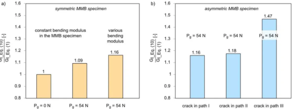
The MMB specimens with geometrical and material properties described in Tab. 2, loaded by constant force P = 500 N were used to compare the Eq. (10) and Eq. (1). Fig. 5 presents ratios between Eq. (10) and Eq. (1) with taking various effects into account.
crack position
thickness [mm] bending stiffness [GPa×mm4]
h1 h2 H E1I1 E2I2 E3I3
Path 0 6.7 6.7 13.4 11 695 11 695 181 594
Path I 5.7 7.7 13.4 9 776 14 808 181 594
Path II 5.32 8.08 13.4 8 439 19 018 181 594
Path III 4.25 9.15 13.4 5 613 35 581 181 594
Table 2: Geometry and bending stiffness of MMB specimens for various crack propagation paths (various degree of asymmetry)
Fig. 5a contains ratio of total strain energy release rate calculated by Eq. (10) and by Eq. (1) for symmetrical specimen. It is clearly visible that when the weight of the lever is neglected (Pg = 0 N) the Eq. (10) and Eq. (1) are identical. For the
present MMB configuration the calculated total strain energy release rate increases at about 9% when the weight of the lever is taken into account. The Eq. (1) contains term E11 that is bending modulus in the longitudinal direction. However,
the bending modulus of the laminate is different from the bending modulus of the laminate joint. If this change of the modulus and weight of the lever is taken into account the total strain energy release rate increase at about 16% in comparison with Eq. (1). Fig. 5b shows comparison of total strain energy release rate calculated by Eq. (10) and by Eq. (1) for asymmetrical specimens where weight of the loading lever is taken into account. Here, the asymmetry of the specimen is expressed by crack propagation path where Path I is closest to the plane of symmetry (in a distance of 1 mm). The calculated total strain energy release rates for Path I and Path II are almost the same as for the symmetrical specimen with various bending moduli shown in Fig. 5a. The farther is the crack from the symmetrical plane the higher the strain energy release rate is as document the strain energy release rate for the crack propagating in Path III.
Based on the derivation described above and successfully compared with available relation derived by Reeder and Crews it is possible to consider the Eq. (10) suitable for the calculation of the total strain energy release rate of the adhesively bonded mixed-mode bending test with asymmetric configuration.
M. Ševčík et al, Frattura ed Integrità Strutturale, 34 (2015) 216-225; DOI: 10.3221/IGF-ESIS.34.23
221
FRACTURE CRITERION
he fracture criterion for the crack initiation and crack propagation can be found in the literature [21]. The critical values of the strain energy release rate for the crack initiation and propagation in various crack propagation paths are shown in Tab. 3. More information about the experimental measurement of the fracture criterion can be found in [14].
specime n code
lever dimensio
n [mm]
crack initiation crack propagation in Path I
crack propagation in Path II
crack propagation in Path III
c cg GI GII Gtot GI GII Gtot GI GII Gtot GI GII Gtot
MMB-01
227 54
205 85 290 1061 287 1348 102
4 144 1168 MMB-02 166 69 235 410 151 561 963 260 1223
MMB-03 133 55 188 837 226 1063
MMB-04 159 66 225 890 241 1131
MMB-05 163 67 230 497 183 680 924 250 1174 MMB-06
150 38
162 128 290 851 387 1238 383 89 472
MMB-07 210 165 375 550 374 924 1247 567 1814
MMB-08 182 143 325 462 314 776 945 430 1375
MMB-09 182 143 325 1190 541 1731
MMB-10 181 143 324 1012 460 1472 700 164 864
MMB-11 189 149 338 597 406 1003 1302 592 1894
Table 3: Critical strain energy release rate at various paths under different mixed-mode loading in [J/m2] from [14]. Single underlined numbers represent highest recorded values of the group, double underlined values represent lowest recorded values.
RESULTS
he proposed analytical model of the asymmetric MMB test is analyzed in this section. Fracture behavior obtained using the proposed model is compared with experimental data recently obtained by authors and well documented in the literature [14,21].
Effect of fiber bridging length
At first the sensitivity analysis of the fiber bridging length was performed. The total strain energy release rate for crack initiation and crack propagation was kept constant but the fiber bridging length LF was changed in order to study its effect
on the load vs. crack length (P-a) diagram. The shape of the fracture criterion used for this analysis is shown in Fig. 6. Based on the analytical procedure described above it is possible to predict the load vs. crack length diagram assuming that the crack will propagate if the condition Gtot(a)=Gcrit(a), where Gtot(a) is the calculated value of the total strain energy release
rate and Gcrit(a) is the critical value of the total strain energy release rate that can be measured experimentally, Tab. 3.
Example of such prediction is shown in Fig. 7 where experimentally measured and analytically predicted P-a diagrams are plotted when considering fracture in Path II.
By inspecting the Fig. 7 it is possible to conclude that the analytical model is capable to predict the P-a diagram of the MMB test with sufficient accuracy. The fiber bridging length seems to have strong effect on the maximum loading force, however, it has to be mentioned that in reality the critical SERR for the crack propagation Gprop depends on the fiber
bridging length. Generally, the Gprop = Gini when LF = 0 and Gprop increases when LF increases. Therefore, if the values of
Gini and Gprop are known the fiber bridging length can be obtained indirectly using this analytical model in comparison with
T
M. Ševčík et al, Frattura ed Integrità Strutturale, 34 (2015) 216-225; DOI: 10.3221/IGF-ESIS.34.23
222
experimental results. For the studied specimen MMB 02 the fiber bridging length is approx. 35 mm which well corresponds to the experimental observation.
Figure 6: Simplified fracture criterion based on the Gtot
depending on the fiber bridging length.
Figure 7: The effect of fiber bridging length on the load vs. crack length diagram (c = 227 mm, cg = 54 mm).
Crack propagation path
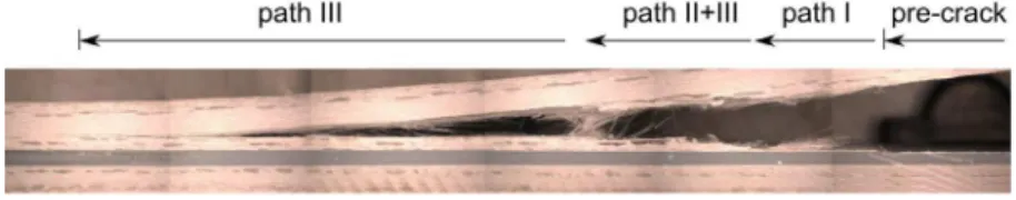
The fracture of the laminate is often accompanied with delamination in the neighboring layers and interfaces between the layers. This phenomenon is shown in Fig. 8 where photograph of the MMB specimen after test is complemented by the crack propagation path description.
Figure 8: Propagation of the crack in multiple paths.
The propagation of the crack in various paths brings another complication for the reliable prediction of the P-a diagram. For the comprehensive prediction of the P-a diagram the crack propagation in multiple paths should be captured. One of the possibilities is to plot P-a diagram for all crack propagation paths and therefore to show bounds in which the P-a diagram of the real structure will fall. The preview of such P-a diagram is shown in Fig. 9 where fiber bridging length of 20 mm is considered.
M. Ševčík et al, Frattura ed Integrità Strutturale, 34 (2015) 216-225; DOI: 10.3221/IGF-ESIS.34.23
223
Fig. 9 also contains overall prediction (green curve) that represents crack initiation in path I, crack propagation in path II and final propagation in path III. Unfortunately, such overall prediction is not possible to construct due to the fact that the crack propagation path is often changed during the crack propagation and sometimes multiple growing cracks in various crack propagation paths can be recorded. On the other hand it is possible to predict upper and lower bounds, see Fig. 10.
Figure 10: Comparison of experimental data from [21] with upper and lower predictions of P-a diagram for specimens MMB-06 to MMB-11 (c = 150 mm, cg = 38 mm).
Fig. 10 shows comparison of experimental data for 6 MMB specimens. The critical values of the strain energy release rate for crack initiation and crack propagation was taken from Tab. 3. The upper (lower) bound was obtained in such a way that the highest (lowest) critical strain energy release rates of the group of specimens were taken as the fracture criterion. These values are highlighted in Tab. 3. It can be seen that that the upper bound prediction for path II well fits with experimental results for crack lengths longer than 80 mm whereas lower bound prediction for path I is valid for crack lengths between 50 – 100 mm. For longer cracks the lower bound prediction for path III is nearest to the lowest experimental results obtained in the MMB test. Similar behavior was found also for other groups of specimens.
Mixed-mode fracture criterion
The predictions described in the previous section were based on the total strain energy release rate fracture criterion. The critical strain energy release rate was experimentally measured for every single specimen and served as the input data for the predictions. However, the fracture criterion based on the total strain energy release rate does not consider the mixed-mode nature on the crack tip and it is therefore limited to adhesively bonded joints where the crack tip mixed-mode-mixity is the same as the experimentally tested MMB specimen. To obtain more general fracture criterion it is important to perform number of mixed-mode delamination tests and experimentally obtain the mixed-mode fracture criterion. Such fracture criterion can be generally written in the following form:
) G , G , a ( G ) G , G , a (
G I II crit I_crit II_crit (11)
where GI_crit, GII_crit are critical strain energy release rates for pure mode I and pure mode II. The criterion can have various
shapes e.g. linear, semi-linear, elliptical, polynomial etc. Preview of the fracture criterion for crack propagation in path II is shown in Fig. 11.
Similarly to the fracture criterion shown in Fig. 11, fracture criteria for crack initiation and crack propagation in various crack propagation paths can be experimentally found. These mixed-mode fracture criteria are necessary for the prediction of P-a diagram using the present analytical model.
M. Ševčík et al, Frattura ed Integrità Strutturale, 34 (2015) 216-225; DOI: 10.3221/IGF-ESIS.34.23
224
comparison of the experimental data points and predicted fracture response for the crack propagating exclusively in Path II using mixed-mode fracture criterion is shown in Fig. 12.
Figure 11: Experimentally obtained fracture criterion based on the mixed-mode delamination tests [14].
Figure 12: Comparison of experimental data points of MMB-01 to MMB-05 from [14] with predicted behavior using mixed-mode fracture criterion (c = 227 mm, cg = 54 mm).
The predicted load vs. crack length diagram using mixed-mode fracture criterion is in both qualitative and quantitative agreement with experimentally obtained data. The scatter in experimental results is far greater than difference between polynomial fit of the experimental data and predicted behavior.
Utilizing the proposed analytical model of asymmetrical mixed-mode bending test together with the mixed-mode fracture criterion opens possibility for optimization of the laminate lay-up, reduction of the specimen size as well as for the design of adhesively bonded joints of more than two laminates. The only requirement is that the stacking sequence of the laminate remains the same in the vicinity of the crack propagation path otherwise new mixed-mode fracture criterion has to be experimentally obtained.
CONCLUSIONS
his paper is focused on the problematic of the mixed-mode bending test of adhesively bonded fiber reinforced polymer composites with special emphasize on the mixed-mode bending test. A new analytical model for the calculation of the total strain energy release rate is derived and compared with well established relation of Reeder and Crews. On the practical example it is shown that for symmetrical MMB specimens the proposed relation gives equivalent values and it is therefore more generalized and possibly applicable for asymmetric specimens.
In the second part of the paper the proposed analytical model is used for the prediction of the load vs. crack length diagram of the MMB test of the real specimens. It is shown that the proposed model can predict the fracture behavior in various layers and therefore to describe the fracture behavior in more details.
The methodology and results presented in this paper could be utilized for the design of both joint geometry and lay-up of the laminates constituting the joint or for the prediction of the fracture behavior of such structures.
ACKNOWLEDGEMENTS
his work was supported through the grant 15-09347S of the Czech Science Foundation and by the Ministry of Education, Youth and Sports of the Czech Republic throughout the Project No. CZ.1.07/2.3.00/30.0063 “Talented postdocs for scientific excellence in physics of materials”.
REFERENCES
[1] Gowayed, Y., Types of fiber and fiber arrangement in fiber-reinforced polymer (FRP) composites. In: Uddin N, editor. Developments in Fiber-Reinforced Polymer (FRP) Composites for Civil Engineering, Woodhead Publishing, (2013) 3-17.
T
M. Ševčík et al, Frattura ed Integrità Strutturale, 34 (2015) 216-225; DOI: 10.3221/IGF-ESIS.34.23
225
[2] Soutis, C., Introduction: Engineering requirements for aerospace composite materials. In: Irving PE, Soutis C, editors. Polymer Composites in the Aerospace Industry, Woodhead Publishing, (2015) 1-18.
[3] Kachanov, L.M., Delamination Buckling. Delamination Buckling of Composite Materials, Springer Netherlands, (1988) 19-56.
[4] Rice, J.R., Elastic Fracture Mechanics Concepts for Interfacial Cracks. J Appl Mech, 55 (1988) 98-103. DOI:10.1115/1.3173668.
[5] D30 Committee. Test Method for Mixed Mode I-Mode II Interlaminar Fracture Toughness of Unidirectional Fiber Reinforced Polymer Matrix Composites. ASTM International, (2013).
[6] Williams, J.G., On the calculation of energy release rates for cracked laminates. International Journal of Fracture, 36 (1988) 101-19. DOI:10.1007/BF00017790.
[7] Kinloch, A.J., Wang, Y., Williams. J.G., Yayla, P., The mixed-mode delamination of fibre composite materials. Composites Science and Technology, 47 (1993) 225-37. DOI:10.1016/0266-3538(93)90031-B.
[8] Ducept, F., Davies, P., Gamby, D., An experimental study to validate tests used to determine mixed mode failure criteria of glass/epoxy composites. Composites Part A: Applied Science and Manufacturing, 28 (1997) 719-729. DOI:10.1016/S1359-835X(97)00012-2.
[9] Hutchinson, J.W., Suo, Z., Mixed Mode Cracking in Layered Materials, In: John W. Hutchinson and Theodore Y. Wu, editor. Advances in Applied Mechanics, 29 (1991) 63-191.
[10]Shahverdi, M., Vassilopoulos, A.P., Keller, T., A phenomenological analysis of Mode I fracture of adhesively-bonded pultruded GFRP joints. Engineering Fracture Mechanics, 78 (2011) 2161-2173.
DOI:10.1016/j.engfracmech.2011.04.007
[11]Bennati, S., Fisicaro, P., Valvo, P.S., An enhanced beam-theory model of the mixed-mode bending (MMB) test—Part I: Literature review and mechanical model. Meccanica, 48 (2013) 443-462. DOI:10.1007/s11012-012-9686-3.
[12]Bennati, S., Fisicaro, P., Valvo, P.S., An enhanced beam-theory model of the mixed-mode bending (MMB) test—Part II: Applications and results. Meccanica, 48 (2013) 465-484. DOI:10.1007/s11012-012-9682-7.
[13]Rybicki, E.F., Kanninen, M.F., A finite element calculation of stress intensity factors by a modified crack closure integral, Engineering Fracture Mechanics, 9 (1977) 931-938. DOI:10.1016/0013-7944(77)90013-3.
[14]Shahverdi, M., Vassilopoulos, A.P., Keller, T., Mixed-mode fatigue failure criteria for adhesively-bonded pultruded GFRP joints. Composites Part A: Applied Science and Manufacturing, 54 (2013) 46-55.
DOI:10.1016/j.compositesa.2013.06.017.
[15]ASTM D3171-11. Test Methods for Constituent Content of Composite Materials. ASTM International, (2011). [16]De Castro, J., Keller, T., Ductile double-lap joints from brittle GFRP laminates and ductile adhesives, Part I:
Experimental investigation, Composites Part B: Engineering, 39 (2008) 271-281. DOI:10.1016/j.compositesb.2007.02.015.
[17]Shahverdi, M., Vassilopoulos, A.P., Keller, T., Modeling effects of asymmetry and fiber bridging on Mode I fracture behavior of bonded pultruded composite joints, Engineering Fracture Mechanics, 99 (2013) 335-48.
DOI:10.1016/j.engfracmech.2013.02.001.
[18]Crews, Jr. J.H., Reeder, J.R., A Mixed-Mode Bending Apparatus For Delamination Testing, NASA TECHNICAL MEMORANDUM 100662. (1988).
[19]Reeder, J.R., Crews, Jr. J.H., Redesign of the mixed-mode bending delamination test to reduce nonlinear effects, Journal of Composites Technology and Research, 14 (1992) 12-9.
[20]Zhang, Y., Vassilopoulos, A.P., Keller, T., Mode I and II fracture behavior of adhesively-bonded pultruded composite joints, Engineering Fracture Mechanics, 77 (2010) 128-43. DOI:10.1016/j.engfracmech.2009.09.015.
[21]Shahverdi, M., Vassilopoulos, A.P., Keller, T., Mixed-Mode I/II fracture behavior of asymmetric adhesively-bonded pultruded composite joints, Engineering Fracture Mechanics, 115 (2014) 43-59.

![Table 1: Material properties and thicknesses of all layers of the laminate and adhesive [17]](https://thumb-eu.123doks.com/thumbv2/123dok_br/18185847.331724/3.892.130.755.372.530/table-material-properties-thicknesses-layers-laminate-adhesive.webp)
![Table 3: Critical strain energy release rate at various paths under different mixed-mode loading in [J/m 2 ] from [14]](https://thumb-eu.123doks.com/thumbv2/123dok_br/18185847.331724/6.892.96.790.266.653/table-critical-strain-energy-release-various-different-loading.webp)
![Figure 10: Comparison of experimental data from [21] with upper and lower predictions of P-a diagram for specimens MMB-06 to MMB-11 (c = 150 mm, c g = 38 mm)](https://thumb-eu.123doks.com/thumbv2/123dok_br/18185847.331724/8.892.221.668.250.520/figure-comparison-experimental-upper-lower-predictions-diagram-specimens.webp)
![Figure 12: Comparison of experimental data points of MMB-01 to MMB-05 from [14] with predicted behavior using mixed-mode fracture criterion (c = 227 mm, c g = 54 mm)](https://thumb-eu.123doks.com/thumbv2/123dok_br/18185847.331724/9.892.81.430.194.408/figure-comparison-experimental-points-predicted-behavior-fracture-criterion.webp)
