Materials Research, Vol. 9, No. 1, 47-49, 2006 © 2006
*e-mail: [email protected]
Comparative Study of CdTe Sources Used for Deposition of CdTe
Thin Films by Close Spaced Sublimation Technique
Wagner Anacleto Pinheiro*, Vivienne Denise Falcão, Leila Rosa de Oliveira Cruz, Carlos Luiz Ferreira
Instituto Militar de Engenharia, Seção de Engenharia Mecânica e de Materiais,
Praça General Tibúrcio, 80, Urca, 22290-270 Rio de Janeiro - RJ, Brazil
Received: December 2, 2004; Revised: July 13, 2005
Unlike other thin ilm deposition techniques, close spaced sublimation (CSS) requires a short source-substrate distance. The kind of source used in this technique strongly affects the control of the deposition parameters, especially the deposition rate. When depositing CdTe thin ilms by CSS, the most common CdTe sources are: single-crystal or polycrystalline wafers, powders, pellets or pieces, a thick CdTe ilm deposited onto glass or molybdenum substrate (CdTe source-plate) and a sintered CdTe powder. In this work, CdTe thin ilms were deposited by CSS technique from different CdTe sources: particles, powder, compact powder, a paste made of CdTe and propylene glycol and source-plates (CdTe/Mo and CdTe/glass). The largest deposition rate was achieved when a paste made of CdTe and propylene glycol was used as the source. CdTe source-plates led to lower rates, probably due to the poor heat transmission, caused by the introduction of the plate substrate. The results also showed that compacting the powder the deposition rate increases due to the better thermal contact between powder particles.
Keywords:CdTe, thin films, CSS
1. Introduction
Cadmium telluride (CdTe) has been shown to be the most prom-ising polycrystalline thin ilm material for producing photovoltaic solar cells because of its high absorption coeficient (> 104 cm-1)
and optimum bandgap (1.5 eV). These ilms have been deposited by several techniques, all of them leading to good quality ilms. The most eficient CdTe solar cell reported so far is a 16.5% device1,
whose CdTe layer was deposited by close spaced sublimation (CSS) technique. This technique involves the sublimation of CdTe from a source which is separated from the substrate by a small distance, usually, millimeters. It is an attractive process since it offers high depositions rates, it is able to produce ilms with larger grains than those deposited by other techniques and can be easily scaled up for manufacturing purposes. Moreover, it does not require any elaborate equipment because the pressures required are in the low vacuum range and the temperatures used are 750 °C at most. Unlike other thin ilm deposition techniques, the use of a short source-substrate distance requires special attention to the kind of source chosen, since the source strongly affects the control of the deposition parameters, especially the deposition rate. When depositing CdTe thin ilms by CSS, the CdTe sources can be found in the following shapes: single-crystal or polycrystalline wafers - frequently used, but as it involves melting of CdTe it is very expensive - powders, grains or pieces. Other sources include yet: a thick CdTe ilm deposited onto glass or molybdenum substrate (CdTe source-plate) and a sintered CdTe powder. In order to guarantee the homogeneity of the CdTe ilms deposited by CSS technique, the main requirements for the source are low porosity and uniformity.
Several authors have proposed different techniques for producing CSS CdTe sources and reported the effects of these sources on the processing of CdTe thin ilms as well2-12.
Higuchi2 observed that, after using the same CdTe powder load
hundred of times, the deposition rate is extremely affected. During the
irst depositions, the deposition rate of the ilm is low, then increasing and stabilizing after the following depositions; however, after several depositions the rate decreases again. They explained that during the irst depositions the source usually has a lot of porosity, leading to a low rate. After using the source several times, there is a sintering of powder particles, which increases the thermal conductivity of the material-source. However, the use of the same source for a long period, leads to the consume of an excessive amount of material and the formation of holes in the source, reducing the deposition rate. Thus only about 10% of the material load is used, which results in a large waste of material.
The research groups in U.S.A3,4 utilize a CdTe source-plate, which
is a thick CdTe ilm deposited on a substrate (molybdenum or glass). The thick ilm can be deposited by CSS itself or other deposition process. Chung5, Kumazawa6, Ahn7, Han8 and Higuchi2 have used
screen-printing technique to produce CdTe thick ilms on glass. A paste made of CdTe powder, or a mixture of Cd and Te powders, and a binder (propylene glycol) is passed through a 150-mesh silk screen onto the glass substrate. Then, this source-plate is dried at 120 °C for 1 hour. Another groups use compact powder sources9, in which
CdTe tablets are made by pressing CdTe powder; sintering sources10,
in which a graphite crucible containing CdTe powder is placed inside an oven, under 50 bar of N2 and 1200 °C for 1 hour, for producing a CdTe sintered tablet; and source-plate made by thermal evaporation of a CdTe ilm on Mo11 or glass12.
48 Pinheiro et al. Materials Research
2. Experimental
The CdTe ilms were deposited on glass substrates previously covered with In2O3:Sn (ITO) in a homemade CSS equipment. Details of this deposition technique can be found elsewhere1. Briely, CSS
process involves the sublimation of a CdTe source which is separated from the substrate by a distance of millimeters. Figure 1 shows a sketch of the deposition set-up. Source and substrate are separated by quartz spacers. Both CdTe source and substrate are supported by graphite blocks, which are heated independently by means of quartz lamps. This assembly is inserted in a quartz tube, which is vacuum sealed. In this work, the source-substrate distance was 2.7 mm. The ilms were deposited under argon atmosphere using the following deposition parameters: source temperature = 700 °C, substrate tem-perature = 530 °C, and pressure = 1 Torr. The thickness of the ilms was measured in a Veeco Dektak 3 proiler. The deposition rates were calculated from the ratio between the ilm thickness and the deposition time. Different CdTe sources were used for depositing the ilms: particles, powder, compact powder, a paste made of CdTe and propylene glycol and source-plates (CdTe/Mo and CdTe/glass). The raw material used in the sources was CdTe 5N (99.999%) – particles sizing 3 to 6 mm - manufactured by CERAC. The procedures below were followed to fabricate the sources:
• Particles: about 1 g of CdTe particles were spread homogene-ously on the graphite source block so that the entire area was covered;
• Powder: CdTe particles were ground and spread over the graphite block surface;
• Compact powder - a 5 g CdTe tablet was produced by pressing CdTe powder;
• Paste - CdTe powder and propylene glycol were mixed to form a paste, which was applied over the graphite block and dried at 200 °C for 1 hour. This procedure differs to those reported at the literature2,5-8, where the paste is usually applied onto a
glass substrate. In our case, the paste was applied directly on the graphite block;
• Source-plate (a): CdTe paste was also used to prepare a source-plate by screen-printing technique; using a 120-mesh silk screen, the paste was applied onto glass substrates and molybdenum foils, which were then heated at 200 °C for 1 hour; and
• Source-plate (b): a CdTe thick ilm was grown inside the CSS system itself; CdTe powder and a glass plate were placed respectively on the source and substrate graphite blocks; by heating the source at 750 °C and keeping the plate at 550 °C and the pressure at 0.1 Torr, the CdTe source plate was obtained.
3. Results and Discussion
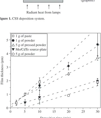
Figure 2 shows the thickness of the CdTe ilms obtained from different sources as a function of the deposition time. It can be ob-served that the deposition rate, given by the angular coeficient of the curve, is constant. As expected, the deposition rate depends on the type of CdTe source. The values are 0.192, 0.158, 0.132, 0.074 and 0.058 µm/min for the paste source, powder source (1 g), compact powder, Mo/CdTe plate and powder source (5 g), respectively. The use of CdTe paste source resulted in the highest deposition rate, although CdTe powder source (1 g) has also promoted a high rate.
When depositing CdTe ilms by CSS it is essential that the mate-rial is homogeneously spread over the source in order to get uniform ilms. The paste source fulills this requirement particularly when small amounts of material are to be spread on a large area source, as the one used in this work (5 x 5 cm2). Furthermore, a paste source
promotes a better agglutination of the particles, giving rising to higher
Radiant heat from lamps
Radiant heat from lamps
Substrate block (graphite) Substrate Spacer (quartz) CdTe source
Source block (graphite) Thermocouples
Figure 1. CSS deposition system.
Film thickness (
M
m)
Deposition time (min)
0 5 10 15 20 25 30
1 g of paste 1 g of powder 5 g of pressed powder Mo/CdTe source-plate 5 g of powder
Figure 2. Thickness of CdTe ilms obtained from different sources as a func-tion of the deposifunc-tion time.
deposition rates. This has also been observed by Higuchi et al.2, who
obtained rates as high as 6 µm/min, when depositing CdTe ilms from a paste source applied on a glass substrate. However, the deposition parameters and the substrates used in their experiments were quite different from ours, which explains the difference between the values of the deposition rates.
In reference to the powder sources, Figure 2 shows that 1 g powder source gives rise to deposition rates higher than those achieved with the 5 g powder sources, probably due to the temperature gradient along the thickness of the source. Also, comparing the 5 g powder source with the compact powder source (5 g) one observes that the compact powder gives a higher rate, due to better thermal contact among the particles.
The deposition rate achieved when CdTe source-plates were used is also shown in Figure 2. Both glass and molybdenum substrates gave similar results. The deposition rate is very low, probably due to the introduction of the substrate plate between the material and the graphite block, which reduced the heat transmission to the mate-rial. However, it should be emphasized that source-plates have been preferred by many groups2-4, mainly due to its easiness of handling
Vol. 9, No 1, 2006 Comparative Study of CdTe Sources Used for Deposition of CdTe Thin Films by Close Spaced Sublimation Technique 49
It is important to mention that, for most of the sources used in this work, the deposition rate always increased after sequential depositions, which has also been observed by Higuchi et al.2. For
example, for the deposition parameters previously described and using a compact powder source, the deposition rate increased twice after the irst deposition. This may be explained considering that during the deposition the source is indeed submitted to a sintering process, which contributes to enhance the thermal conductivity of the CdTe source. This fact should be taken into account when preparing CdTe ilms for solar cells, since the control of deposition rate is fundamental to the microstructure of the ilm. Thus, when using a new source, the irst deposition was always discarded in order to assure that the following depositions were carried out at constant rate.
4. Conclusions
In this work CdTe thin ilms were deposited by CSS method using different types of CdTe sources. It was shown that the deposition rate depends on the way the CdTe source is prepared. The largest deposi-tion rate was achieved when a paste made of CdTe and propylene glycol was used as the source. CdTe source-plates led to lower rates, probably due to the poor heat transmission, caused by the introduc-tion of the plate substrate. The results also showed that compacting the powder, the deposition rate increases due to the better thermal contact between powder particles. Finally, when using a new CdTe source the irst deposition should be discarded, in order to assure that the following depositions are carried out at constant rate.
Acknowledgments
The authors wish to thank Prof. R. Prioli, from Pontifícia Universidade Católica do Rio de Janeiro (PUC-RJ), for thickness measurements. This work was supported by Centro de Pesquisas da Petrobras (CENPES/PETROBRAS).
References
1. Wu X, Dhere R, Albin D, Gessert T, Dehart C, Keane J et al. High-ef-iciency CTO/ZTO/CdS/CdTe polycrystalline thin-ilm solar cells. NREL/ CP-520-31025. 2001 [cited 2004 Jul 15]; 3. Available from: http:\\www. osti.gov/bridge.
2. Higuchi H, Kumazawa S, Arita T, Hanafusa A, Murozono M, Aramoto T. Method for preparing CdTe ilm and solar cell using the same. United States Patent. 1999; 5994642. p. 7.
3. Mathew X, Arizmendi J, Campos J, Sebastian P, Mathews N, Jiménez C et al. Shallow levels in the band gap of CdTe ilms deposited on metallic substrates. Solar Energy Materials & Solar Cells. 2001; 70(3):381.
4. Moutinho H. [personal communication]. 2003 Jul 5.
5. Chung G, Park S, Cho K, Ahn B. Electrical properties of CdTe ilms prepared by close-spaced sublimation with screen-printed source layers. Journal of Applied Physics. 1995; 78(9):5493.
6. Kumazawa S, Shibutani S, Nishio T, Aramoto T, Higuchi H, Arita T et al. 15.01% highly eficient thin ilm CdS/CdTe solar cell. Solar Energy Materials & Solar Cells. 1997; 49(1-4):210.
7. Ahn B, Han B, Chung G. Photovoltaic properties of CdTe solar cells fabricated by close spaced sublimation with screen printed CdTe sources. Solar Energy Materials & Solar Cells. 1998; 50(1-4):155.
8. Han B, Park S, Ahn J, Ahn B. Photovoltaic properties of close-space sublimated CdTe solar cells. Solar Energy Materials & Solar Cells. 1998; 64(1):49.
9. Bonnet D, Henrichs B, Jager K, Ritcher H. Methods of making pn CdTe/ CdS thin ilm solar cells. United States Patent. 1994; 5304499. p. 6.
10. Romeo N, Bosio A, Tedeschi R, Canavari V. Growth of polycrystalline CdS and CdTe thin layers for high eficiency thin ilm solar cells. Materi-als Chemistry and Physics. 2000; 66(2-3):203.
11. Seth A, Lush G, Mcclure J, Singh V, Flood D. Growth and characterization of CdTe by close space sublimation on metal substrates. Solar Energy Materials & Solar Cells. 1999; 59(1-2):38.