Static and Dynamic Analysis of 1 220 mm Steel Last Stage Blade
for Steam Turbine
T. M´ıˇsek
a,∗, Z. Kub´ın
aaˇ
SKODA POWER a. s., Tylova 57, 316 00 Plzeˇn, Czech Republic
Received 31 August 2008; received in revised form 18 November 2008
Abstract
The 3 000 rpm 1 220 mm blade for a steam turbine was developed with application of new design features. The last stage moving blade is designed with an integral cover, a mid-span tie-boss connection and a fir-tree dovetail. With this configuration the blades are continuously coupled by the blade untwist due to the centrifugal force when the blades rotate at high speed, so that vibration control and increased structural damping are provided. Blade was tuned in order to eigen-frequencies were safely far from possible excitation. Because of connection members, the number of the resonant vibration modes can be reduced by virtue of the vibration characteristics of the circumferentially continuous blades. The last stage airfoil was optimalized from view of minimalization of its centrifugal force. In order to develop the 3 000 rpm 1 220 mm blade, the advanced analysis methods to predict dynamics behavior of the bladed structure were applied. Coupled rotor-blade analysis was also aim of the attention. To validate calculated results the verification measurement such as rotational vibration tests was carried out in the high-speed test rig. Relation of the friction damping of the bladed structure on amount of excitation level was also monitored and evaluated.
c
2009 University of West Bohemia. All rights reserved.
Keywords:dynamics, steam turbine, last stage blade, friction damping, vibration measurement, coupled vibration
1. Introduction
The today’s power generation market requests for steam turbines high efficiency and low cost products. Key factor in fulfilling these demands is the increase of exhaust area: efficiency is increased by reducing exhaust losses and lower cost is reached by reducing the number of flows. The steam turbine last stage blade (LSB) is one of the most important components which affect turbine efficiency, output and the size of the whole turbine structure. Based on these incentives, a last stage with 48” (1220mm) steel moving blade for 3000 rpm applications has been developed jointly by ˇSkoda Power and Ansaldo Energia.
In the past such long blade for 3 000 rpm application was only made of a titanium alloy [2, 6]. At the beginning of this decade several world leading companies introduced steel 48” blade [1, 3]. The development of the new LSB 48” requires superior experience in aerodynam-ics, non-linear structural techniques and structure dynamics. The new blade design is character-ized by continuous coupling of adjacent blades which brings additional damping coming from connecting members. Two connecting members are utilized at the blade, one at the tip plays role of the shroud and the second connecting member (tie-boss) is approximately placed in the middle of the blade length.
This paper presents mechanical development of the LSB 48” and appropriate calculation techniques like nonlinear structure analysis, modal analysis and coupled rotor-blade analysis. Most computed results are then compared with the measurement at a high-speed balance test facility.
2. Mechanical Design
2.1. General
As stated before, the continuously coupled blade structure is adopted for the LSB48” by the use of the integrally coupled tip cover and the tie-boss at the mid span. The structure is realized by constraining untwist at contact surfaces. This type of the blade connection structure provides additional rigidity and damping.
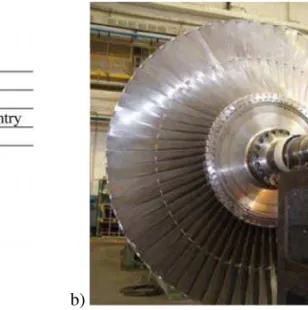
a) b)
Fig. 1. a) View of LSB 48” and its specification, b) Test rig rotor
Vibration characteristics of the continuously coupled blade structure strongly depend on ad-justed gaps at contact interfaces. Therefore it is necessary for correct design of contact members to perform an accurate untwist analysis. Large deformation nonlinear behaviour is important to consider since untwist itself is large deformation phenomenon. Based on untwist analysis the appropriate gaps at the standstill condition are adjusted between adjacent contact interfaces. In case of LSB 48” the gap was set up to 1.1 mm at the shroud and 1.3 mm at the tie-boss respectively.
2.2. Material
The moving blade made of steel must be capable of withstanding the stress induced by centrifu-gal force. One of the key factors that plays main role for developing the 50 Hz blade of length 1 220 mm are material properties.
Table 1. Mechanical properties of the steel S45 000
Yield stress [MPa] 1 103
Tensile strength [MPa] 1 172
Elongation [%] Min. 12
2.3. Airfoil Design Optimalization
The last stage blade is exposed to very high centrifugal load due to its large length. This fact influences a design both the airfoil itself and the blade attachment together with the disk. The centrifugal force of the single blade can reach several hundreds tons. The main motivation was to reduce centrifugal loads as much as possible, however, aerodynamics of the blade must not be negatively affected. A smaller centrifugal load brings as saving of the disk size which has positive influence on an overall turbine size as increasing number of start-ups from view of low cycle fatigue. To achieve the minimal centrifugal load of the airfoil an optimalization process was developed.
Fig. 2. Simplified airfoil scheme
First the static balance equation for infinite element was established as fig. 2 depicts. It implies differential equation (1). Boundary condition (2) for a cross section areaALat the tip is
given by aerodynamics limitation. A tensile stressσLat the tip location is defined by a weight
of the shroud. There are also restrains as for distribution of section areaA(y)along the length as for tensile stressσ(y)as statements (3) and (4) define. It is assumed that the blade rotates with angular speedω.
A′
A = −
ω2
·ρ·(R+y) +σ′
σ , (1)
A(L) = AL; σ(L) =σL, (2)
dA
dy < 0 ∀y∈ 0, L, (3)
σ(y) ≤ σD ∀y∈ 0, L, (4)
M =
L
0
a) b)
Fig. 3. a) Distribution of tensile stress at airfoil, b) Cross section area distribution
A solution of the equation (1) has to fulfil minimalization function (5) which represents static moment of the airfoil related to rotational axis. A numerical solution of the optimalization problem gives relationA=A(y)as fig. 3b presents. Distribution of tensile stress at the airfoil is shown in fig. 3a.
A final minimalized value of the centrifugal load reaches4.9×106
N for specific allowable stressσD.
3. Finite Element Non-linear Static Structure Analysis
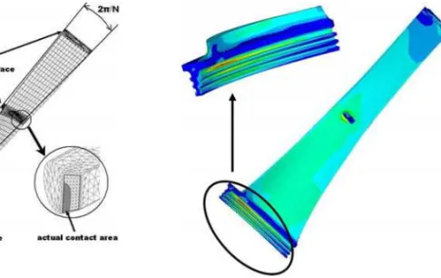
Steady stress distribution at the blade and the disk under the centrifugal force was calculated us-ing the finite element method. The advantage of the structure periodicity was taken into account when creating FE model as fig. 4 depicts. Number of Dofs was around 500 000. Connection between the disk and the blade was realized by means of contact elements. The same type of contact elements were also applied between adjacent friction members. Nonlinear analysis capable of handling the large deformation was required since airfoil deplanation takes place during its centrifugal loading. Elasto-plastic material behavior was set in order to get the real stress distribution at the blade. To save computation time and hardware requirements, FE mesh was formed relatively coarse as fig. 4 shows. Afterwards a submodeling technique had to be uti-lized to obtain correct magnitudes of the local stresses specifically at the curved dovetail where most the stress concentrations exist. Example of stress distribution at the blade presents fig. 5.
Some of resulted peaks stresses at fillets exceed significantly yield stress of the material, however, there is no way to avoid it. Therefore they were analyzed from view of low cycle fatigue (LCF) when a load cycle is defined as startup and shut-down of a turbine. It was found out that the number of cycle is the most limitation factor from view of static structure analysis. However, LSB48” still fulfils all safety criteria for a reliable operation.
4. Dynamic Structure Analysis
4.1. Modal Analysis
Fig. 4. Finite element mesh for structural analysis Fig. 5. Example of Von Mises stress distribution
The advantage of the structure periodicity was taken into account. Periodicity interfaces are depicted in fig. 4. Based on the nonlinear structure analysis actual contact areas were identified at the shroud and the tie-boss as fig. 4 schematically shows. These contact area represents periodicity interfaces. This assumption comes true in the case when excitation load is small enough and doesn’t affect a size and a shape of calculated steady state contact areas. This implies that linear behavior of the bladed structure is considered when the modal analysis is performed.
Neglecting dissipation effects, the harmonic free vibration of the blade structure is given by the matrix equation (6). This assumption comes true when friction damping is very low and if only natural frequencies are the point of interest.
[M]{¨x}+ [K]{x}={0}. (6)
[M] and[K]represent the bladed segment mass and nonlinear stiffness matrices with re-spect to the rotational speedΩ. The complex vector{x}describes the nodal displacement of vibration. Between nodes located on the right and left circumferential segment sides, cyclic kinematics constrains are imposed as
{x}right={x}lef teipϕ, (7)
whereφ= 2π/N is the circumferential periodicity angle of the disk sector and the harmonic indexpvaries according to
p= 0,1,2,3, . . .
N/2 forNeven
(N−1)/2 forNodd
and N defines number of segments (in our caseN is a number of blades). Effect of stress stiffening and dynamic softening has to be considered since they influence natural frequencies of LSB48” significantly.
Fig. 6. Interference diagram for LSB 48” at 3 000 rpm Fig. 7. Coupled rotor-blade mode shape
4.2. Coupled rotor- blade frequency analysis
Blade and disk vibrations can be strongly interconnected. This coupling effect occurs between a rotor torsional mode shape and a zero nodal diameter (0ND) bladed disk mode shape. Since damping for torsional vibrations is rather small (i.e. about 0.1 % of critical damping) resonance conditions have to be investigated very carefully. For a numerical calculation the complex model of the rotor and blades must be considered. In the past only 1D elements were used for modelling both rotor and blades interaction [5]. However, for continuously coupled blade structure using of 3D element is more adequate in order to reach the most accurate results of coupled natural frequencies.
In order to save computation time periodicity of the structure was taken into account again, however, only for the bladed structure. It means the single blade was modeled with solid ele-ments and in the same way as mentioned in the section 4.1. The rotor train system was modeled by using 1D element and eventually with lump mass. However, if only one blade is considered its mechanical properties must be modified since a relation between inertia mass of the rotor itself and the blade row to must be kept. Also a relation between rigidity of the rotor and the blade row must be preserved.
A coupled rotor blade frequency was calculated for the test rig rotor in order to compare both the measured and the calculated frequencies. Fig. 7 shows coupled rotor-blade mode shape which was aim of our interest. The tab. 2 presents both measured and calculated natural frequencies and shows their excellent matching. This fact gives high confidence in usage of the FE model for other numerical calculations i.e. for actual rotor train systems which can consist from up to six bladed rows.
Since off frequency operation can occur during turbine life, the natural frequency shift re-lating to variation of a rotor speed was also aim of interest as tab. 2 presents.
Table 2. Natural frequency shift relating to rotor speed
Speed [RPM] Measured 0ND frequency [Hz] Calculated 0ND frequency [Hz]
2 850 103.8 104.0
3 000 107.2 107.0
Based on the measured and calculated coupled 0ND frequencies for the test rig rotor, the very accurate and thorough coupled rotor-blade analysis has to be carried out for every rotor train system since the coupled 0ND frequency is close to double grid frequency.
To get better view on the coupled frequency, an eigenvalue problem for the system of two discrete masses connected by a spring with a stiffnessk, was solved. A natural frequency for such system is given by relation (8)
fcoupled=funcoupled
1 + IBlades IRotor
, (8)
wherefuncoupledis a natural frequency for single mass-spring system represented by the stiffness
kand inertia massIBlades,IRotordefines the inertia mass of the second mass.
The relation (8) reveals that more massive rotor with a larger inertia mass degreases the coupled natural frequency of the rotor bladed system.
The application of LSB48” at an actual rotor train must be well investigated since coupled 0ND frequency of actual system will be certainly closer to double grid frequency than in the case of the test rig rotor.
5. Rotational test
The vibration characteristics of the actual full scale LSB48” were measured and verified through rotational vibration tests. The test should have also proved that a friction damping takes place during blade operation. Blades were fitted to the test rig rotor as fig. 1b shows and the rotor was placed to a vacuum chamber made just for such kind of tests. The rotor is powered by an electrical AC motor. It enables to harmonically vary its torque in order to simulate rotor-generator vibration during negative sequence current fault on the rotor-generator.
As it is well known from literature [4], contact members should exhibit additional damping due to friction. The level of damping is a function of whether friction damping takes place during blade operation the measurement procedure was suggested.
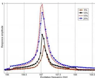
Four levels of torsional excitation were applied, specifically 5 %, 10 %, 15 %, 20 % of nom-inal motor torque. Excitation frequency was swept from 98 Hz to 110 Hz with step 0.1 Hz and there was 5 s dwell at each frequency.
The test proved nonexistence of resonance points near their rated speed. Response amplitude at the specific point (fillet below the tie-boss) of a blade was picked-up for all level of excitation as fig. 8 depicts. A frequency shift due to nonlinearity was not observed. It can be explained by insufficient level of the excitation to cause the shift. The damping ratio was investigated for each amplitude response characteristics as tab. 3 presents. Increasing trend of the damping ratio δrelating to the excitation moment is evident.
Table 3. Identified damping ratioδ
Excitation torque [%] Damping ratioδ
5 3.8e−4
10 4.2e−4
15 6.0e−4
Fig. 8. Measured amplitude-frequency characteristics at 3 000 RPM for four level of excitation
The measurement of amplitude-frequency characteristics clearly reveals nonlinear behavior of “20 %” towards to the case “15 %”. This statement comes from comparison of resonance amplitudes for “15 %” and “20 %” this nonlinear effect can be likely contributed to existence of the friction damping at the contact members. This conclusion will be further verified by the next measurement for excitation levels 25 % and 30 %.
Feedback obtained from tests will give powerful experience and knowledge for developing other new continuously coupled blades.
6. Conclusion
The 1 220 mm steel last blade for a 3 000 rpm unit has been developed. Mechanical strength of the developed blade has been confirmed by the over-speed rotational test. The vibrational test proved no nonexistence of resonance points near their rated speed. Excellent matching of calculated and measured eigen-frequencies was reached that gives confidence in the numerical FE model. New last stage blade is applicable not only for new turbines but also for the turbine refurbishment. As aerodynamics calculation predicts there should be high improvement in effi-ciency compare to the present last stage blade. Feedback obtained from tests will give powerful experience and knowledge for developing other new continuously coupled blades.
References
[1] D. Hober, J. Selpski, Aerodynamic Design and Development of Steel 48/40Inch Steam Turbine LP End Bucket Series, Proceeding of ICOPE 2003, pp. 217–222.
[2] R. Kaneko, et al., Development of 40-in Turbine Blades Using Titanium Alloys, Proc. EPRI Work-shop Titanium Steam Turbine Blading, 1988, pp. 111–128.
[3] Y. Kaneko, et al., Development and Verification of 3 000 rpm 48inch Integral Shroud blade for Steam Turbine, Proceedings of ASME Conference, PWR2005-50347, Chicago, USA, 2005. [4] K. Koh, J. Griffin, Characterization of Turbine Blade Friction Dampers, Transaction of ASME,
2005, vol. 127, pp. 856–862.
[5] R. Reid, Coupled Blade-Rotor Torsional vibration Component and Low Pressure Blade Retrofit Issues, Proceedings of Power Generation Conference – ASME, 1995.
![Table 1. Mechanical properties of the steel S45 000 Yield stress [MPa] 1 103 Tensile strength [MPa] 1 172 Elongation [%] Min](https://thumb-eu.123doks.com/thumbv2/123dok_br/18422690.361076/3.892.381.522.508.787/table-mechanical-properties-yield-stress-tensile-strength-elongation.webp)