ABSTRACT: Flow ield around rotors in axial light is known to be complex especially in steep descent where the rotor is operating inside its own wake. It is often reported that, in this light condition, the rotor is susceptible to severe wake interactions causing unsteady blade load, severe vibration, loss of performance, as well as poor control and handling. So far, there is little data from experimental and numerical analysis available for rotors in axial light. In this paper, the steady Reynolds-Averaged Navier-Stokes Computational Fluid Dynamics solver Helicopter Multi-Block was used to predict the performance of rotors in axial light. The main objective of this study was to improve the basic knowledge about the subject and to validate the low solver used. The results obtained are presented in the form of surface pressure, rotor performance parameters, and vortex wake trajectories. The detailed velocity ield of the tip vortex for a rotor in hover was also investigated, and a strong self-similarity of the swirl velocity proile was found. The predicted results obtained when compared with available experimental data showed a reasonably agreement for hover and descent rate, suggesting unsteady solution for rotors in vortex-ring state.
KEYWORDS: Axial light, CFD, Performance, Rotor, Wake structure.
Performance and Wake Analysis of
Rotors in Axial Flight Using Computational
Fluid Dynamics
Nik Ahmad Ridhwan Nik Mohd1, George Barakos2
INTRODUCTION
In axial light, particularly in steep descent where helicopter enters vortex-ring state (VRS), a rotor descends into its own wake. VRS is one of the extreme axial light conditions and a potentially hazardous light regime of operation where rotor blades are known to experience severe thrust luctuations, highly unsteady blade airloads, aperiodic blade lapping, severe vibration, and sudden loss of aircrat altitude and control (Drees and Hendal 1951; Brinson and Ellenrieder 1998; Conlisk 2001; Leishman 2006; Brand et al. 2011). his problem is even more dangerous when helicopters operate close to the ground, which may cause unwanted accidents.
Several experiments and computational studies for low speed descending light have been reported in literature, but relatively a few show detailed quantitative measurements of rotor performance and blade aerodynamic characteristics. Drees and Hendal (1951) are among the irst to capture the flow field around rotors in axial flight. The airflow near a rotor installed in the wind tunnel was made visible by using a number of smoke generators. From the experiment, a large low circulation was captured at the tip of the blade in VRS, and a periodic tumbling motion of the rotor was observed. Another study on measuring rotor performance in axial light was carried out by Caradonna (1999). he climb performance of a scale model of UH-1H rotor was measured in the wind tunnel at a constant blade tip speed combined with various climb rates and blade collective pitch angles. he rotor cyclic was not considered throughout the test, and the results were
1.Universiti Teknologi Malaysia – Faculty of Mechanical Engineering – Aeronautical Laboratory – Johor Bahru/Johor – Malaysia. 2.University of Glasgow – School of Engineering – CFD Laboratory – Glasgow – Scotland.
Author for correspondence: Nik Ahmad Ridhwan Nik Mohd | Universiti Teknologi Malaysia – Faculty of Mechanical Engineering – Aeronautical Laboratory | 81310 Skudai | Johor Bahru/Johor – Malaysia | Email: [email protected]
also compared to the HELIX-I code. he experimental results provided good quantitative rotor performance and a wake geometry database for Computational Fluid Dynamics (CFD) validation. he diiculties to get accurate rotor performance in hover from experiments, however, required an extrapolation technique to the limit of 0 climb speed. Instead of using a wind tunnel, Washizu et al. (1966) used a towing basin to measure a single rotor performance in axial light. he use of large towing basin in their research was intended to eliminate blockage efects encountered in wind tunnels with closed test sections. Rotor performance for a range of descent speeds was presented in the form of a polar curve and compared with momentum theory. here are several other experiments on scaled rotor in axial light (Green et al. 2005; McAlister et al. 2001). Brinson and Ellenrieder (1998) concluded that the entry to the fully developed vortex ring state was found to be sensitive to tunnel velocity and large changes in cyclic required to trim. Due to the extremely complex low ield near the rotor and the lack of data, rotor blade aerodynamics in axial light is still not well understood.
A number of computer researches to model helicopter low ields have also been reported. However, most of these focused on hover and forward light, and only a few on axial light. he PHIDIAS project provided a platform for the numerical simulation of the 6075 Dauphin VRS and windmill-brake states (WBS) (Bailly 2010). he HOST method was compared with the time-marching, unsteady wake model developed by MINT and light test data conducted by ONERA at the CEV French Flight Centre. Most of computational luid dynamics (CFD) solvers developed for rotor aerodynamic simulation are based on solving the Reynolds-Averaged Navier-Stokes equation and are susceptible to excessive numerical dissipation of vorticity on coarse meshes. If not controlled, this dissipation leads to the loss of coherence of vortical structures within the low. To control this numerical dissipation and dispersion of vorticity in the low ield, a vorticity transport model was developed and tested on rotor in descent (Ahlin and Brown 2005; Line and Brown 2004).
In this study, the Helicopter Multi-block (HMB) CFD solver has been used to compute the performance of rotors at various rates of descent. he main objectives of this paper are to improve basic knowledge of rotor aerodynamics and to validate the low solver. he results obtained are presented as surface pressure, rotor performance parameters, and vortex wake trajectories. he detailed velocity ield of the tip vortex for rotor
in hover is also investigated, and a strong self-similarity of the swirl velocity proile is found. he predicted results obtained were compared with available experimental data and showed a reasonably agreement for hovering and moderate rate of descent.
CFD FLOW SOLVER
he description of the HMB is discussed in detail by Barakos
et al. (2005) and Steijl et al. (2006), being briely presented in this paper. HMB is a computational luid dynamic Navier-Stokes solver developed at the CFD Laboratory of the University of Liverpool and runs on parallel distributed memory computers. HMB solves the 3D Unsteady Reynolds-Averaged Navier-Stokes (URANS) equations on multi-block structured meshes using a cell-centred inite-volume method for spatial discretisation. In this study, the convective terms are discretised using the Osher’s scheme. he Monotone Upstream-centred Schemes for Conservation Laws (MUSCL) interpolation is used to provide formally 3rd-order accuracy in the calculation of luxes. he van Albada limiter is used to avoid spurious oscillation in the low properties across shocks by locally reducing the accuracy of the numerical scheme to irst order. he resulting linear system of equations is solved using a pre-conditioned Generalised Conjugate Gradient method in conjunction with a Lower Upper factorisation. For unsteady simulations, implicit dual-time stepping is used based on Jameson’s pseudo-time integration approach. he viscous computations use the k-ω
baseline (BSL) and the Shear Stress Transport (SST) turbulence model of Menter (1994). he SST blends the k-ω model for the inner boundary layer with the k-ε model for the outer boundary layer. Furthermore, the redeined SST eddy viscosity accounts for the efect of transport of turbulent shear stress. he SST model has been used for many external lows with adverse pressure gradients. he solver also has been used and validated for several fundamental lows apart from rotor cases (Badcock
et al. 2000; Gagliardi and Barakos 2008).
can be found in Steijl et al. (2006). For hovering and climbing rotor cases, the momentum based far ield boundary model, assuming a three-dimension source-sink singularity at the rotor axis of rotation and at a rotor plane was used (Steijl et al. 2006; Srinivasan 1993). For ascending and descending rotor, the vertical velocity is added to the hover velocity. he Froude/ Source-sink condition typically used (Steijl et al. 2006) for applying the boundary conditions in hover and descending light at moderate speeds was not adequate for the extreme cases considered here. herefore, in this paper, for extreme case in descending light, a free-stream condition was assumed at the far ield. For more eicient computations, the vortex-tube model that valid for most of axial light condition can be used (Wang 1990; Perry et al. 2007; Nik Mohd and Barakos 2010).
CFD MESH GENERATION AND TEST CASES
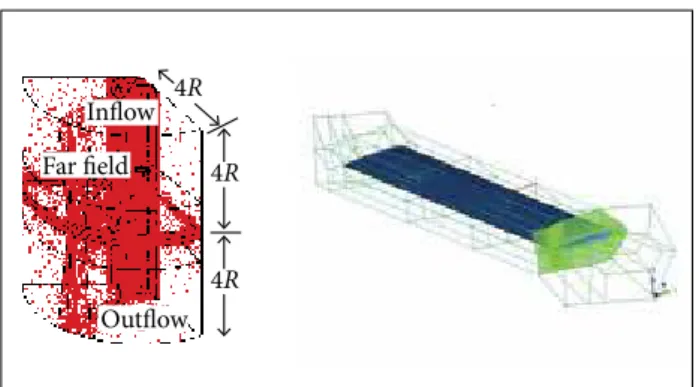
A structured C-H-H CFD mesh was employed (Fig. 1). An H-type structure was used away from the blades with a C-type structure attached to them. his type of mesh topology allows for accurate viscous computations and can provide a mechanism for pitching the blades, with the near-blade mesh remaining in an undeformed state (Brocklehurst et al. 2008). For all meshes, viscous spacing in the direction normal to the blade surface with the irst cell located at 10−5c
above the blade and exponential distribution was employed. For viscous cases, this mesh spacing constructed results in
y+< 1. he rotor centre of rotation is located at the z-axis, the
rotor blade is laid on the x-axis, and the quarter chord point is taken at y = 0 with the blade leading edge pointing at the positive y-axis. his geometry was used for the construction of the computational meshes for the rotors in axial light. he rotor hub was modelled as a simple straight cylinder. Summary of rotor geometry and low condition considered in this study are shown in Table 1.
RESULTS AND DISCUSSION
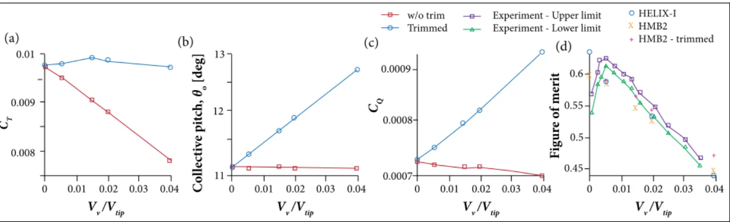
ASCENDING CARADONNA UH-1H ROTORFor ascending case, the aerodynamic performance and wake geometry of the Caradonna UH-1H rotor were computed for a range of ascend rates, Vv /Vtip ,from hover to ascending rate of 0.04. he results are presented for a blade at trimmed and untrimmed conditions. For untrimmed condition, the rotor blade collective pitch angle, θo, was set at 11° as in Caradonna (1999) experiment. For trimmed conditions, the thrust required for ascend was maintained constant closed to the hover state (Fig. 2a). This is done by considering the incremental of the blade collective pitch settings by 3/4 Vv /Vtip (Johnson 1980). he coning angle was set at 0 for all calculations. For the ascending test cases considered, the linear increments in the blade collective pitch resulting from the trimmed conditions are plotted in Fig. 2b. he blade tip Mach number was
Mtip = 0.5771 and the Reynolds number, Re = 1.028 × 10⁶.
Rotor trimming requires an increment in blade collective pitch angle to maintain the rotor thrust as the ascend speed ratio is increased. This also results in an increment of the rotor torque required (Fig. 2c). For the test cases considered, the rotor losses its eiciency in ascending light. Comparison with the experimental measurements (Fig. 2d) shows that HMB underpredicts rotor igure of merit (FM) but is in good agreement with HELIX-I data for ascending cases.
Figure 1. Multi-block mesh employed in HMB.
Inlow
Far field 4R 4R
Outflow 4R
Table 1. Summary of rotor geometries for axial light test cases.
Characteristic UH-1H Washizu
Rotor geometry
Number of blades 2 3
Root cut-out 1 c 1 c
Rotor radius 13.67 c 16.67 c (1.1 m)
Chord 1 c 1 c (0.33 m)
Aspect ratio 13.67 16.67
Twist Untwisted −8.33°
Solidity 0.047 0.0573
Blade proile NACA 0012 NACA 0012
Flow condition
Tip Mach 0.5771 0.1693
Reynolds number (× 106) 1.028 0.1306
Grid size (× 106) 9 6.3
Number of blocks 170 272
Predictions of hover FM were successfully presented in Nik
Mohd et al. (2011) for the case of Caradonna and Tung (1981).
here are, however, some discrepancies for the UH-1H rotor for both HMB and HELIX-I data. In experiments, the drop in the value of FM is expected due to excessive flow unsteadiness (Caradonna 1999), and extrapolation to ascend was suggested to correct the hover FM. he predicted hover FM shows a linear trend; however, the value of the FM falls between the experiments and the HELIX-I data. Overall, for the ascending rotor, the
0 0.01 0.01
0.009
0.02
Vv /Vtip
CT 0.03 0.04 0.008 0 0.01 13 12 0.02
Vv /Vtip
C o ll ec tiv e p it ch, θo [d eg] 0.03 0.04 11 0 0.01 0.0009 HELIX-I HMB2 HMB2 - trimmed
0.0008
0.0007
0.02
Vv /Vtip CQ
0.03 0.04 0 0.01 0.6
0.02
Vv /Vtip
F ig ur e o f me ri t 0.03 0.04 0.55 0.5 0.45 w/o trim Trimmed
Experiment - Upper limit Experiment - Lower limit
X X + + + + + X X X X –1 1 0.5 0 –0.5 –1 –1.5 –2 –0.8 –0.6 –0.4
Y/c
–0.2 0 P ress ur e c o effi ci en t, CP –1 1 0.5 0 –0.5 –1 –1.5 –2.5 –2 –0.8 –0.6 –0.4
Y/c
–0.2 0 P ress ur e c o effi ci en t, CP –1 1 0.5 0 –0.5 –1.5 –1 –2 –2.5 –3 –3.5 –0.8 –0.6 –0.4
Y/c
–0.2 0 P ress ur e c o effi ci en t, CP –1 1 0.5 0 –0.5 –1 –1.5 –2.5 –2 –0.8 –0.6 –0.4
Y/c
–0.2 0 P ress ur e c o effi ci en t, CP 1 0.4 0.5 0.6 0.7 0.8 0.9 0.8 0.7 0.6
r/R
0.5 0.4 L ift c o effi ci en t, CI Hover
Climb (V/Vtip = 0.0054)
Climb (V/Vtip = 0.0054)
Climb (V/Vtip = 0.0054)
Climb, ROC = 0.0054 Climb, ROC = 0.02 Climb, ROC = 0.04
Figure 2. Performance of the Caradonna UH-1H rotor in hover and vertical ascent. (a) Thrust coeficient; (b) Collective pitch; (c) Torque coeficient; (d) Figure of merit.
predicted rotor performance without trimming is in excellent agreement with experiments and HELIX-I data. Nevertheless, when the rotor trim condition is activated, a slight increase is observed in the rotor FM for the fast ascending case (Fig. 2d).
Figures 3a to 3d show the blade surface pressure coeicient,
CP, at 3 blade stations plotted for diferent ascend rates. From
the comparison, the blade surface pressure is found to have the same stagnation values, but decreasing suction pressure, as rotor
ascend rate increases. he distributions of spanwise blade lit
Figure 3. Comparison of CFD results of the Caradonna UH-1H blade surface pressure coeficients at different ascent rates. (a) r/R = 0.30; (b) r/R = 0.70; (c) r/R = 0.90; (d) r/R = 0.99; (e) Lift coeficient. ROC: Rate of climb.
10
0.8
0.6
0.4
0.2
0 100 200
Wake age, ψw
r
/
R
, z
/
R
300 400
10
0.8
0.6
0.4
0.2
0 100 200
Vortex age [deg]
r
/
R
, z
/
R
300 400
r/R
z/R
CFD - r/R (hover)
CFD - z/R (hover)
Experiment - r/R
(Vv /Vtip = 0.0054)
Experiment - z/R
(Vv /Vtip = 0.0054)
r/R - Experiment
z/R - Experiment
r/R - w/o trim
z/R - w/o trim
r/R - trimmed
z/R - trimmed
+ x
Vorticity magnitude
Vv/Vtip = (Hover)
Vv/Vtip = 0.04 (Trim)
Blade
0.3431 0.3153 0.2876 0.2598 0.2320 0.2043 0.1765 0.1488 0.1210 0.0933 0.0655
0.927c
2.634c
Figure 4. Normalised radial (r/R) and vertical (z/R) displacement of rotor tip vortex for θ0.7 = 11° and
Mtip = 0.5771.(a) Hover; (b) Vv /Vtip = 0.015.
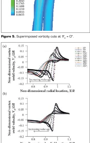
Figure 6. Distribution of vortex swirl velocity of the UH-1H rotor in ascending light. (a) Vv /Vtip = 0 (Hover); (b) Vv /Vtip = 0.04.
Figure 5. Superimposed vorticity cuts at Ψw = 0°.
coeicient, CL, are presented in Fig. 3e and were obtained by
integrating the CP. From the igure, the spanwise CL is found
shifted vertically downwards as the normalised ascending velocity increases from hover to 0.04.
he vertical and axial rotor tip vortex trajectories obtained from CFD, and compared with the No. 1 blade of (Caradonna 1999) experiment are shown in Figs. 4a to 4b. It can be seen that, for low ascending speed, the calculated wake trajectories are in good agreement with the experimental data of Caradonna (1999). It can also be noted that the overall wake geometry is almost identical or independent of trim conditions. he comparison of the blade tip vortices for hovering and ascending flight cases represented by superimposed vorticity-cuts taken
at Ψw = 0°is depicted in Fig. 5, where, for the hovering case
of Vv /Vtip = 0, the primary blade tip vortex of blade No. 1
ater a complete revolution is predicted to be at 0.927 chord downstream the rotor plane. For a low ascending light case of
Vv /Vtip = 0.04, the primary blade tip vortex predicted by HMB is found to be displaced 2.634 chord downstream the rotor plane. However, due to the fast growth in the mesh spacing due to the exponential distribution used has resulted in a quick dissipation and dispersion of vorticity ield.
he distributions of vortex swirl velocity normalised with the rotor tip speed across the tip vortex cores for various wake ages are shown in Fig. 6. his information also shows how strong the axial velocity induced by the tip vortex is. he vortex swirl velocity of the tip vortex weakens as it evolves
(a)
(a)
(b)
20,000 –0.002
40,000 60,000 80,000
Work units
T
o
rq
u
e c
o
effi
ci
en
t,
CQ
–0.015 –0.01 –0.0005 0 0.0005 0.001 0.0015 0.002
20,000 0
40,000 60,000 80,000
Work units
T
o
rq
u
e c
o
effi
ci
en
t,
CQ
0.005 0.01 0.015 0.02 0.025 0.03 0.035
0.04 HoverVortex-ring
Windmill x
+
but grows in core radius. Furthermore, for the same wake age considered, the vortex swirl velocity is found to be stronger in hover compared to the ascending flight. his quantity may be influenced by the dissipation of vorticity due to coarse mesh constructed below the rotor plane where an exponential point distribution was used.
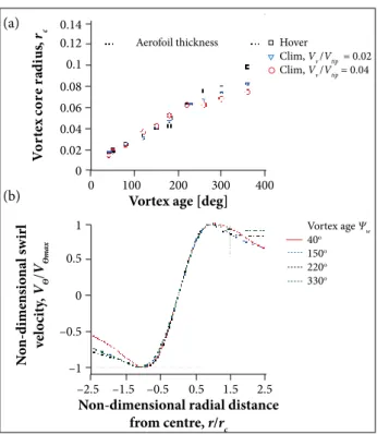
he growth of the tip vortex core extracted for one rotor revolution is presented in Fig. 7a. It is found that, for the same mesh distribution, the core radius increases linearly with vortex age and grows faster in hovering flight. Similarly to the hovering cases, the tip vortex of an ascending rotor looks self-similar when the normalised swirl velocity of the core is plotted against the normalised radial distance (Fig. 7b).
Non-dimensional radial distance from centre, r/rc
N
o
n-dime
ns
io
na
l s
w
irl
vel
o
ci
ty
,
VѲ
/
VѲm
ax
–2.5 –1.5 –0.5 0.5 1.5 2.5
–1 –0.5 0 0.5
1 Vortex age Ψw
40o
150o
220o
330o
Vortex age [deg]
V
o
rt
ex
c
or
e r
ad
iu
s,
rc
0 100 200 300 400
0 0.08 0.12 0.14
Hover
Clim, Vv /Vtip = 0.02
Clim, Vv /Vtip = 0.04
Aerofoil thickness
0.1
0.06 0.04 0.02
Figure 7. Predicted core growth and self-similarity of the UH-1H rotor tip vortices at different ascent rates. (a) Vortex core radius; (b) Vortex self-similarity.
DESCENDING WASHIZU ROTOR
Experiment for rotors in descending flight performed by Washizu et al. (1966) were referred in this study. In the experiment, the rotor was tested in a towing basin with the aim of eliminating the blockage efect that occurs in most wind tunnel experiments.
he experiments of the Washizu rotor in descending flight
include hover, vortex-ring state (Vv /Vtip= 0.054, Vv= 3.11 m/s)
and wind-mill brake state, WBS (Vv /Vtip = 0.09, Vv = 5.184 m/s),
and these were computed using CFD. he test cases consider the blade tip Reynolds and Mach numbers ixed to a constant
value of 1.306 × 10⁶ and 0.1693, respectively. he rotor has 3
blades, and the blade collective pitch setting varied from 0°, 4.5° to 8°. he descending flight was simulated by increasing the descend speed while keeping the rotor tip speed constant. In CFD, the freestream far ield boundary was speciied for rotors in descending flight, and a Froude (source-sink) condition was used for the hovering flight case. he turbulence closure was
achieved using the 2 equations of the k-ω model with transport
of shear stress (SST) and baseline (BSL) variant. Figures 8a and 8b show the convergence history for rotor thrust and torque coeicients. It can be seen that rotor thrust and torque in WBS
fluctuate even ater 80,000 iteration steps. his behaviour is
apparently caused by the highly separated low developed on the upper blade surface. In descending light, the rotor blades experience a low coming from below the rotor plane.
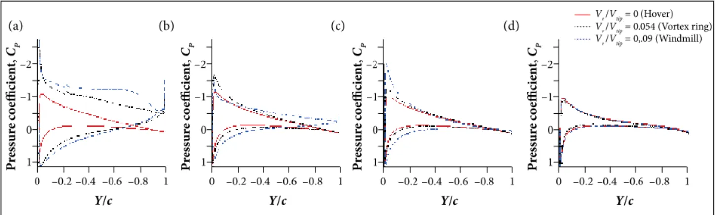
he comparisons of the chordwise blade surface pressure at 3 blade stations (r/R = 0.3, 0.75, and 0.9) are presented in Fig. 9. he results suggest that the blade in VRS and WBS has large low separation on the upper surface of the blade. his situation occurs up to r/R = 0.75. he chordwise plot of low streamlines visualised at 3 blade stations are shown in
Figure 8. Convergence history plots for the Washizu rotor in descending light (θ
0.7 = 8°, Mtip = 0.1693). (a) Thrust history; (b) Torque history.
(a) (a)
1.5 1 0.5 0 –0.5 –1.5
–1.5 –0.5 0 0.5 1.5
Y/c Z/c 1 –1 –1 1.5 1 0.5 0 –0.5 –1.5
–1.5 –0.5 0 0.5 1.5
Y/c Z/c 1 –1 –1 2 1.5 1 0.5 0 –1
–1.5 –0.5 0 0.5 1.5
Y/c Z/c 1 –1 –0.5 1.5 1 0.5 0 –0.5 –1.5
–1.5 –0.5 0 0.5 1.5
Y/c Z/c 1 –1 –1 1.5 1 0.5 0 –0.5 –1.5
–1.5 –0.5 0 0.5 1.5
Y/c Z/c 1 –1 –1 1.5 1 0.5 0 –0.5 –1.5
–1.5 –0.5 0 0.5 1.5
Y/c Z/c 1 –1 –1 –0.2 0 1 0 –1 1 –0.4
Y/c
P ress ur e c o effi ci en t, C P –0.6 –0.8 –2 –0.2 0 1 0 –1 1 –0.4
Y/c
P ress ur e c o effi ci en t, C P –0.6 –0.8 –2 –0.2 0 1 0 –1 1 –0.4
Y/c
P ress ur e c o effi ci en t, C P –0.6 –0.8 –2 –0.2 0 1 0 –1 1 –0.4
Y/c
P ress ur e c o effi ci en t, C P –0.6 –0.8 –2
Vv /Vtip = 0 (Hover)
Vv /Vtip = 0.054 (Vortex ring)
Vv /Vtip = 0,.09 (Windmill)
Figure 9. Comparison of CFD results of the Washizu rotor blade surface pressure coeficient at different descent rates (θ
0.7 = 8°, Mtip = 0.1693). (a) r/R = 0.30; (b) r/R = 0.75; (c) r/R = 0.90; (d) r/R = 0.99.
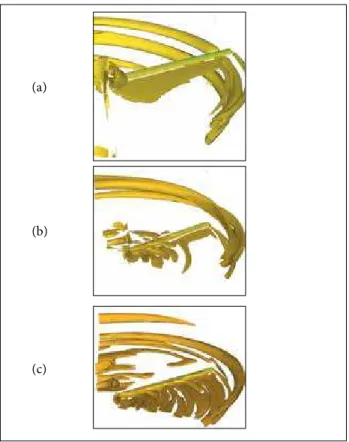
Figs. 10 and 11. As shown in Fig. 10, for the rotor in VRS, the
blade at 20%R experiences leading edge separation and then
growth to fully separated flow on the upper blade surface at
40%R. A much more severe flow separation can be veriied for
the blade in windmill brake as shown in Fig. 11, where almost
75%R of blade is separated.
For hovering rotor, the flow ield enters the computational domain from all directions and is induced downstream below the rotor. In descending flight, however, the inflow velocity enters the domain from the boundary located below the rotor plane. In the VRS, where the transport of vorticity is approximately equal to the rate of descent, a large recirculation
Figure 10. Streamlines and contour of pressure coeficient for rotor in VRS (θ
0.75 = 8°, Mtip = 0.1693). (a) r/R = 0.20; (b) r/R = 0.40; (c) r/R = 0.70.
Figure 11. Streamlines and contour of pressure coeficient for rotor in WBS (θ
0.75 = 8°, Mtip= 0.1693). (a) r/R = 0.20; (b) r/R = 0.40; (c) r/R = 0.70.
(a)
(a) (b) (c) (d)
(a)
(b)
(b)
(c)
flow exists near the blade tip. Nevertheless, the mesh setting used was still unable to accurately capture the collection of tip vortices accumulated in this recirculation flow as found in most experiments. In the windmill brake state, where the rotor experiences a fast descent rate, the flow ield continues to expand above the rotor plane. Iso-surfaces of Q-criterion coloured by pressure are depicted in Fig. 12. he Q-criterion is used here to visualise the highly concentrated vorticity regions by plotting the rotation-dominated strain in the flow. A large area of fully turbulence flow is seen to be developed around the rotor in WBS.
he comparisons of the rotor performance in terms of
torque coefficient (CQ)versus thrust coefficient (CT)and
FM versusCT are given in Fig. 13. he efects of diferent
turbulence models (k-ω BSL and SST) and trim conditions
are also presented. he results suggest that, for low collective pitch settings, the CFD slightly overpredicts rotor torque for all test cases. Trimming the rotor improves the performance prediction compared to the untrimmed condition. Moreover,
for a high collective pitch setting, a large ofset of rotor torque was observed.
he FM of rotors in hover is plotted for diferent blade collective pitch settings in Fig. 13b. he CFD results show a
well predicted FM for non-liting rotor (CT = 0), but this value
is slightly below the experimental results for the 4.5°and 8°pitch settings. From these results, it can be concluded that the CFD method used can predict rotor performance in steep descent up to an acceptable accuracy.
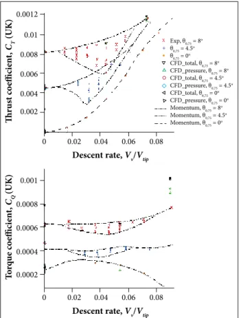
Comparisons of the predicted rotor performance (trimmed condition) against momentum theory and experiments are shown in Fig. 14. As explained in the previous section, the rotor was trimmed to a speciic thrust coeicient. he efect of trimming can be seen on the torque coeicient required to maintain the rotor descend speed for a particular rotor thrust and blade collective angles. here are discrepancies in torque prediction between CFD and the other 2 data. hese could be due to potential errors in the experiments at high pitch angles and high rates of descent due to limited speed of the carriage, and the length of the track (Washizu et al. 1966).
Figure 12. Vortical structures of rotors in descending light visualised using iso-surface of Q-criterion coloured by pressure contour (θ
0.75 = 8°, Mtip = 0.1693). (a) Vv /Vtip = 0 (Hover); (b) Vv /Vtip = 0.054 (Vortex ring); (c) Vv /Vtip = 0.09 (Windmill brake).
0 0.002 0.004
Total thrust coefficient, CT (UK)
F
ig
ur
e o
f me
ri
t
F
ig
ur
e o
f me
ri
t
0.006
θ0.75 = 0
θ0.75 = 8 θ0.75 = 8
θ0.75 = 1.2
θ0.75 = 4.5
0.008 0.7
0.6
0.5
0.4
0.3
0.2
0.1
0
0 0.002 0.004
Total thrust coefficient, CT (UK)
0.006 θ0.75 = 0
θ0.75 = 1.2
θ0.75 = 4.5
0.008 0.0002
0.0003 0.0004 0.0005 0.0006 0.0007 0.0008
Experiment
CFD, k-ω SST, 8o Trimmed CFD, k-ω SST, 4.5o Trimmed CFD, k-ω BSL, 4.5o Trimmed CFD, k-ω SST, 4.5o Untrimmed CFD, k-ω SST, 0o Untrimmed
x
Figure 13. Performance of the Washizu rotor in hover. (a) CT versus CQ; (b) Figure of merit versus CQ.
(a)
(a)
(b)
(b)
Furthermore, no detailed discussion on the hover and windmill test cases was given.
x +
0 0.02
0.0002 0.0004 0.0006 0.0008 0.001
0.04 0.06 0.08
Descent rate, Vv/Vtip
T
o
rq
u
e c
o
effi
ci
en
t,
CQ
(UK)
0 0.02
0.002 0.004 0.006 0.008 0.01 0.0012
0.04 0.06 0.08
Descent rate, Vv/Vtip
Thr
us
t c
o
effi
ci
en
t,
CT
(UK) Exp, θ
0,75 = 8 o θ0,75 = 4.5
o θ0,75 = 0o CFD_total, θ0,75 = 8
o CFD_pressure, θ0,75 = 8
o CFD_total, θ0,75 = 4.5
o CFD_pressure, θ0,75 = 4.5
o CFD_total, θ0,75 = 0o CFD_pressure, θ0,75 = 0
o Momentum, θ0,75 = 8
o Momentum, θ0,75 = 4.5
o Momentum, θ0,75 = 0
o
data. However, for low ascending rate, small discrepancies can be observed. his is expected due to the aperiodicity and recirculation of the flow ield in the wind tunnel rather than CFD errors. Similar hover test cases were also employed for validation including the hovering Caradonna-Tung model rotor, with good success. For the same wake age considered, the distribution of the normalised vortex swirl velocity across the vortex core in climb was found to be weaker and smaller in radius than for the rotors in hover. Furthermore, the tip vortex showed more contraction in hover and fast descending than for ascending flight.
When the rotor descended into its own wake, a large flow separation developed on the upper surface of the blade
extending up to 55%R. A more severe and chaotic flow ield
was observed for the rotor in windmill brake state where more
than 75%R of the blade span experienced stall. he predictions
of thrust and torque showed that the blade collective pitch had to be trimmed to the required thrust. he used of the baseline
(BSL) and shear stress transport (SST) k−ω turbulence models
showed little influence on the torque predictions.
Overall, the present work on rotors in axial flight has successfully validated the HMB solver using several rotor test data. he work presented, provides additional knowledge on rotor performance but there are still certain areas that are not well understood. Although CFD can be a good tool in predicting the basic flow physics on diferent axial flight regimes, future work and validation against new experiments are needed. his calls for experiments in various regimes of axial flight that should be the target of large international initiatives and should result in open databases of measurements.
ACKNOWLEDGEMENTS
The authors would like to acknowledge the Malaysian Ministry of Higher Education and Universiti Teknologi Malaysia for inancial support for this research project.
AUTHOR’S CONTRIBUTION
Mohd NARN performed the numerical calculation and prepared the igures; Barakos G conceived the idea and co-wrote the main text. All authors discussed the results and commented on the manuscript.
Figure 14. Comparison of the Washizu rotor performance plotted for different descent rates and collective pitch settings.
CONCLUSIONS
Accurate prediction of rotor blade aerodynamics in axial flight is a challenging task in computational fluid dynamics. his is due to the presence of large-scale vortical structures that interact with the blade near the tip and need to be accurately modelled. In this study, the performance of rotors in various axial flight conditions in vertical ascend, hover, and descent was computed using the Helicopter Multi-block (HMB) flow solver.
REFERENCES
Ahlin GA, Brown RE (2005) Investigating the physics of rotor vortex ring state using the vorticity transport model. Proceedings of the 31st European Rotorcraft Forum; Florence, Italy.
Badcock K, Richards B, Woodgate M (2000) Elements of computational luid dynamics on block structured grids using implicit solvers. Progr Aero Sci 36(5-6):351-392. doi: 10.1016/S0376-0421(00)00005-1
Bailly J (2010) A qualitative analysis of vortex ring state entry using full time marching unsteady wake model. Proceedings of the 34th European Rotorcraft Forum; Liverpool, UK.
Barakos G, Steijl R, Badcock K, Brocklehurst A (2005) Development of CFD capability for full helicopter engineering analysis. Proceedings of the 31st European Rotorcraft Forum; Florence, Italy.
Brand A, Drier M, Kisor R, Wood T (2011) The nature of vortex ring state. J Am Helicopter Soc 56:1-14. doi: 10.4050/JAHS.56.022001
Brinson P, Ellenrieder T (1998) The nature of vortex ring state. Proceedings of the 24th European Rotorcraft Forum; Marseille, France.
Brocklehurst A, Steijl R, Barakos G (2008) CFD for tail rotor design and evaluation. Proceedings of the 34th European Rotorcraft Forum; Liverpool, UK.
Caradonna FX (1999) Performance measurement and wake characteristics of a model rotor in axial light. J Am Helicopter Soc 44(2):101-108. doi: 10.4050/JAHS.44.101
Caradonna FX, Tung C (1981) Experimental and analytical studies of a model helicopter rotor in hover. NASA-TM-81232.
Conlisk AT (2001) Modern helicopter rotor aerodynamics. Progr Aero Sci 37(5):419-476. doi: 10.1016/S0376-0421(01)00011-2
Drees JM, Hendal WP (1951) Airlow patterns in the neighbourhood of helicopter rotors: a description of some smoke tests carried out in a wind‐tunnel at Amsterdam. Aircr Eng Aerosp Tech 23(4):107-111. doi: 10.1108/eb032021
Gagliardi A, Barakos GN (2008) Improving hover performance of low-twist rotors using trailing-edge laps — a computational study. Proceedings of the 34th European Rotorcraft Forum; Liverpool, UK.
Green RB, Gillies EA, Brown RE (2005) The low ield around a rotor in axial descent. J Fluid Mech 534:237-261. doi: 10.1017/ S0022112005004155
Johnson W (1980) Helicopter theory. Princeton: Princeton University Press.
Leishman JG (2006) Principles of helicopter aerodynamics. Cambridge: Cambridge University Press.
Line AJ, Brown RE (2004) Eficient high-resolution wake modelling using the vorticity transport equation. Proceedings of the 60th Forum of the American Helicopter Society; Baltimore, USA.
McAlister KW, Huang SS, Abrego AI (2001) A model rotor in axial light. NASA/TM-2001-210925.
Menter FR (1994) Two-equation eddy-viscosity turbulence models for engineering applications. AIAA J 32(8):1598-1605. doi: 10.2514/3.12149
Nik Mohd NAR, Barakos GN (2010) Computational aerodynamics of hovering helicopter rotors. Proceedings of the 2010 RAeS Aerodynamics Conference; Bristol, United Kingdom.
Nik Mohd NAR, Barakos GN, Batrkov AS, Kusyumov AN, Nikolaev EI (2011) Computational aerodynamics of rotors in hover and vertical climb. Transactions of Academenergo 4:118-129.
Perry FJ, Chan WFY, Simon I, Brown RE, Ahlin GA, Khelifa BM, Newman SM (2007) Modelling the mean low through a rotor in axial light including vortex ring conditions. J Am Helicopter Soc 52(3):224-238. doi: 10.4050/JAHS.52.224
Srinivasan GR (1993) A free-wake Euler and Navier-Stokes CFD method and its application to helicopter rotors including dynamic stall. Mountain View: JAI Associates, Inc.; [accessed 2017 Jan 6]. http://oai.dtic.mil/oai/ oai?verb=getRecord&metadataPreix=html&identiier=ADA275416
Steijl R, Barakos G, Badcock K (2006) A framework for CFD analysis of helicopter rotors in hover and forward light. Int J Numer Meth Fluid 51(8):819-847. doi: 10.1002/ld.1086
Wang SC (1990) Analytical approach to the induced low of a helicopter rotor in vertical descent. J Am Helicopter Soc 35(1):92-97. doi: 10.4050/JAHS.35.92