Chemical Looping Combustion of Rice Husk
Rashmeet Singh Monga
1, Ganesh R. Kale
2, Sadanand Y. Guhe
11
(Chemical Engineering Dept., Jawaharlal Nehru Engineering College, Aurangabad, India) 2
(Solid and Hazardous Waste Management Division, CSIR-NEERI, Nagpur, India)
ABSTRACT
A thermodynamic investigation of direct chemical looping combustion (CLC) of rice husk is presented in this paper. Both steam and CO2 are used for gasification within the temperature range of 500–1200˚C and different amounts of oxygen carriers. Chemical equilibrium model was considered for the CLC fuel reactor. The trends in product compositions of the fuel reactor, were determined. Rice husk gasification using 3 moles H2O and 0 moles CO2 per mole carbon (in rice husk) at 1 bar pressure and 900˚C was found to be the best operating point for hundred percent carbon conversion in the fuel reactor. Such detailed thermodynamic studies can be useful to design chemical looping combustion processes using different fuels.
Key Words
- Chemical looping combustion, NiO, Rice husk, Thermodynamic study.I.
Introduction
CO2 emission to the environment is mainly contributed by industrial power generation. Concerns for climate change phenomenon have started special procedures to reduce CO2 emissions using CO2 capture and storage techniques that capture CO2 from energy-intensive processes and then store it in suitable geologic locations [1]. The concerns of increase in greenhouse gas emissions and an inevitable global warming crisis is reported by researchers. CO2 is also largely generated by fossil fuel processing and it is a crucial greenhouse gas that affects the climate change [2]. Fossil fuels are at present the major energy resources and are likely to dominate for more several decades. Hence it is essential to continue the use of fossil fuels but also reduce the CO2 emissions to the atmosphere [3]. The expectations from the Carbon capture and storage (CCS) technologies to help curb the greenhouse gas emissions and ensure a sustainable development of power generation and other energy-intensive industrial sectors are extremely high. Amongst them, chemical looping systems display a promising option to capture CO2 with lower cost and energy penalty [1]. Chemical looping combustion (CLC) is a promising technology to utilize fossil fuel for combustion and prevent CO2 dilution in the nitrogen rich flue gases. In this process, a solid oxygen carrier supplies the oxygen needed for CO2 and water formation that is a nitrogen free product mixture. This avoids the major cost of CO2 separation from the flue gases and also reduces the NOx formation. A good oxygen carrier readily reacts with the fuel gas and shall be reoxidized upon being contacted with oxygen. An oxygen carrier is generally prepared by a metal oxide and an inert binder that provide the oxygen storage, fluidizability and mechanical strength [4]. Chemical looping
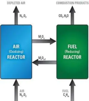
combustion (CLC) is a non-flame two-step combustion which produces a pure CO2 stream for easy compression and sequestration. The process comprises of two interconnected fluidized bed reactors where the fuel reactor is a bubbling fluidized bed and the air reactor is a conventional circulating fluidized bed. It uses an oxygen carrier - a highly-reactive metal particle, to avoid the direct contact of air and fuel during the combustion, to indirectly transport oxygen from the air to the fuel. The products of combustion are kept separated from the rest of the flue gases namely nitrogen and excess oxygen [5]. The CLC system is composed of two reactors, an air and a fuel reactor, as shown in fig. 1
Fig. 1- Chemical-looping combustion system.
In CLC, the solid oxygen carrier is circulated between the air and fuel reactors. The fuel is fed into the fuel reactor where it is oxidized by the lattice oxygen of the oxygen carriers and the reaction in the fuel reactor is almost endothermic.
(2n +m) MexOy +CnH2m→ (2n + m) MexOy−1 + mH2O + nCO2.
Once fuel oxidation is completed; the reduced metal oxide MyO(x−1) is transported to the air reactor where it is reoxidized according the reaction:
MexOy−1 + ½ O2 → MexOy
The flue gas stream from the air reactor will have a high temperature and contain N2 and some unreacted O2.
Transition metal oxides, such as Ni, Fe, Cu, and Mn oxides are reported as reactive oxygen carriers. Ni-based oxygen carriers have exhibited the best reactivity and stability during multi-redox cycles [6]. Henrik Leion et al. has investigated the feasibility of using three different solid fuels in chemical-looping combustion (CLC) using NiO as oxygen carrier in a laboratory fluidized-bed reactor system at 970°C. They reported that the NiO particles also showed good reactivity with methane and a syngas mixture of 50% H2 and 50% CO also showed good fluidizing properties without any signs of agglomeration [7]. Tobias Mattisson et al. have investigated the feasibility of using NiO as an oxygen carrier with CH4 as fuel and in the temperature range 700– 1200°C during chemical-looping combustion and their result showed that the yield of CO2 and H2O decreased with increase in temperature [8]. M.M. Yazdanpanah et al. has presented a reactor model for combustion of CH4 with NiO/NiAl2O4 oxygen carriers in the fuel reactor of a 10 kW CLC pilot plant. The model shows good agreement with experimental results considering some kinetic and hydrodynamic modifications, including impact of gas adsorption by falling particles in the bubble phase on the gas exchange coefficient and thermodynamic limitation of CO and H2 combustion [9]. C. Saha et al. have carried out an experimental investigation pertaining to CLC of a Victorian brown coal using NiO and CuO as oxygen carriers at 950 °C (NiO) and 800°C (CuO) and have reported the high reactivity of CuO as compared to NiO during cyclic operation [10]. Magnus Rydén et al. have examined the Ce, Ca, or Mg stabilized ZrO2 oxygen carriers by redox experiments in a batch fluidized-bed reactor at 800– 950°C, using CH4 as fuel. The experiments showed good reactivity between the particles and CH4 [11].
Many studies have also demonstrated the feasibility of using CLC for both gaseous and solid fuels [12]. The chemical looping process was mainly
targeted towards efficient carbon capturing [13, 14] and hydrogen production [15, 16]. Rutuja Bhoje et al. have done theoretical study of chemical looping combustion of methane to consider some key technology development points to help the process engineer choose the right oxygen carrier and process conditions [17]. X. Wang et al. have developed a three-dimensional numerical model to simulate the CLC process in the fuel reactor using a bubbling fluidized bed of oxygen carrier made from 14 wt% of metal oxide CuO and 86% wt of inert material Al2O3 and a coal gas from coal gasification containing 55 vol. % CO, 30 vol. % H2 and 15 vol. % CO2 [18].
India produces approximately 120 million tons of paddies each year which gives around 24 million tons of rice husk and 4.4 million tons of rice husk ash every year. Rice husk is a high calorific value renewable fuel and can be used for electricity generation in efficient manner [19]. Rice husk can be used as fuel and has oxygen in its structure [20]. The CLC of rice husk has not been studied so far in literature.
II.
Process Design:
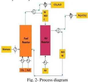
The conceptual process design for CLC of rice husk is shown in figure 2. The process scheme consists of a CLC fuel reactor and air reactor. Preheated rice husk, CO2, H2O and NiO from air
reactor are fed to the fuel reactor in calculated amount to convert the rice husk to CO2, and H2O.
The fuel reactor products were assumed to be in thermodynamic equilibrium at the exit of the reactor. Complete conversion of rice husk and maximum CO2
production are targeted in the fuel reactor. It is assumed that the NiO oxidizes the carbon and hydrogen in rice husk to CO2 and H2O in the CLC
fuel reactor. The moles of OC (NiO) for fuel reactor are varied depending on the stoichiometric requirement of reaction between rice husk and NiO. Complete conversion of rice husk to CO2 and H2O is
desired; however the conversion is limited by thermodynamic equilibrium.
The OC (NiO) is reduced (to Ni) in the CLC fuel reactor. The products of the CLC fuel reactor go through a gas-solid separator and the gaseous products mostly containing CO2 and H2O can be
cooled for CO2 separation and sequestration with
heat recovery or recycled back as required. The solid products of the CLC fuel reactor containing OC are transferred to the air reactor, in which preheated air is added to completely oxidize coke to CO2 and
regenerate the reduced OC. Complete conversion is assumed in these oxidation reactions.
The regenerated oxygen carrier (NiO) is separated from the air reactor product stream using a gas-solid separator and is recycled to the fuel reactor. The air reactor is the major source of thermal energy in this process. It is safely assumed that both the air and fuel reactors operate at same temperature and pressure conditions.
Table 1- Rice husk composition [21].
The base composition of rice husk taken were 1 mole C, 0.6402 moles hydrogen (H2), 0.3052 oxygen
(O2). According to rice husk composition reaction
involved in fuel reactor assumed to be
C+ 0.6402H2(g) + 0.3052O2 (g) + 2.0298NiO = CO2 (g) + 0.6402H2O (g) + 2.0298Ni. (1)
III.
Process Methodology
:
Thermodynamic analysis of the system helps us to determine the optimum conditions that can maximize the yield with low energy consumption [22]. HSC Chemistry software version 5.11 is used to generate the thermodynamic equilibrium data for CLC fuel reactor in this process study. The thermodynamic equilibrium calculations in the Gibbs routine of HSC Chemistry are done using the Gibbs free energy minimization algorithm. The Gibbs program searches the best combination of most stable species in which the Gibbs free energy of the system can achieve its minimum at a fixed mass balance (a constraint minimization problem), constant pressure, and temperature. Hence no chemical reaction equations are required in the input.
The chemical species such as C(s), CO2 (g), H2
(g), CO (g), H2O (g), CH4 (g), H2O (l), O2 (g), NiO
(s) and Ni (s), that are usually found in CLC reaction system considered in this study. The input species fed to the fuel reactor were rice husk with oxygen carrier, H2O (g), and CO2 (g). The material balances
are done by Equilibrium Composition module of
HSC Chemistry and the results were used to calculate reaction enthalpy by Reaction Equation module of HSC Chemistry software.
Table 2- Fuel reactor feed condition with NiO in stoichiometric ratio.
1 mol carbon (in rice husk) is used as basis for all calculations in the temperature range of 500–
1200˚C for the entire process. The feed gasifying agent-to-carbon ratio (GaCR) ranging from 1 to 3 was used in this study. The CLC of rice husk using both gasifying agent (CO2 and H2O) and oxygen
carrier (NiO) is studied with intermediate steps of increase in CO2 moles (with simultaneous decrease
in steam moles) for constant GaCR ratios. These feed conditions for CO2 and steam input per mole carbon
(in rice husk) are shown in Table 2. These inputs
were used to calculate the thermodynamic
equilibrium composition in the CLC fuel reactor. The oxidation reaction in the air reactor is exothermic. It is presumed that, according to stoichiometric amount given by the reactions the air is supplied to the air reactor:
Ni + 0.5O2 = NiO (2)
C + O2 = CO2 (3)
IV.
Results and Discussions:
4.1. Effect of Amount of oxygen carrier:
The stoichiometric quantity of NiO was varied according to fuel reactor reaction of oxygen carrier:
C + 0.6402H2(g) + 0.3052 O2 (g) + 2.0298 NiO =
CO2 (g) +0.6402H2O (g) + 2.0298 Ni
Stoichiometric amount of NiO reqd. (S) = 2.0298
Assuming S = 2.0298
Species C H2 O2
1.25*S = 2.53725
And 1.5*S = 3.0447
The effect of stoichiometric amount of oxygen carrier on CLC of rice husk was investigated for 1, 1.25, and 1.5 stoichiometric of NiO in fuel reactor.
Some side reactions also take place in the fuel reactor and hence the conversions in the fuel reactor are limited by thermodynamic equilibrium constraints. It was necessary to study the equilibrium product composition of the CLC fuel reactor at 1 bar pressure. Since, the OC is generally used in excess of the stoichiometric requirement in CLC processes to enhance the syngas and CH4 conversion in the fuel reactor. Hence two more cases (1.25S and 1.5S) using higher amounts (1.25 times and 1.5 times the stoichiometric requirement) of OC were also studied.
4.1.1. (CH4 + CO + H2) formation:
The (CH4 + CO + H2) compositions in product gases at 1 bar pressure and at 700°C of the CLC fuel reactor for different inputs of OC and different input feed conditions are shown in Figure 3. It was observed that the H2, CO, and CH4 emissions from the fuel reactor decreased with increase in the amount of OC. At constant GaCR, it was also observed that the (CH4 + CO + H2) moles generally decreased with increase in feed CO2 moles (with simultaneous decrease in H2O moles). The maximum amount of (CH4 + CO + H2) exit moles were found to be 0.19 moles for case CS1, while the minimum quantity of (CH4 + CO + H2) exit moles were observed to be 0.02 moles (AS1).
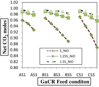
4.1.2. CO2 Emission:
The CO2 emissions at 1 bar pressure and 700°C of the CLC fuel reactor for different inputs of OC and different input feed conditions is shown in Fig. 4. It was seen that the CO2 emission from the fuel reactor increase with increase in the amount of OC. It was also observed that the product CO2 moles generally decrease with increase in feed CO2 moles
at constant GaCR. The maximum amount of CO2 emission was found to be 0.99 moles for case AS1, while the minimum CO2 emission was observed to be 0.87 moles (CS4).
4.1.3. Syngas ratio:
The syngas ratio at 1 bar pressure and at 700°C of the CLC fuel reactor for different inputs of OC and different input feed conditions is shown in Fig. 5. It was observed that the syngas ratio remains constant irrespective of increase in the amount of OC. It was also observed that the syngas ratio generally decreased with increase in feed CO2 moles at constant GaCR. The maximum syngas ratio was found to be 5.73 (CS1), while the minimum of syngas ratio was observed to be 0.25 (CS4). This constant syngas ratio observation is reported for the first time in this paper.
4.2 Effect of GaCR Conditions and Temperature.
4.2.1. Net CO2 emission:
The Net CO2 emissions from the CLC process is used to measure the CO2 utilization and is shown in Fig. 6. The net CO2 emission (moles) = CO2 moles (in output) - CO2 moles (in input). An increase in
0.00 0.02 0.04 0.06 0.08 0.10 0.12 0.14 0.16 0.18 0.20
AS1 AS3 BS1 BS3 BS5 CS1 CS3
(CH
4+
C
O
+
H
2)
m
ol
e
s
GaCR Feed conditon
Fig. 3- (CH4+ CO + H2) moles emittedfrom the fuel reactor at 700˚C.
S_NiO 1.25S_NiO 1.5S_NiO 0.80 0.82 0.84 0.86 0.88 0.90 0.92 0.94 0.96 0.98 1.00 1.02
AS1 AS3 BS1 BS3 BS5 CS1 CS3
Ne
t C
O
2m
oles
GaCR Feed conditon
Fig. 4- CO2 moles emitted from the fuel reactor at 700˚C.
S_NiO 1.25S_NiO 1.5S_NiO 0.00 1.00 2.00 3.00 4.00 5.00 6.00 7.00
AS1 AS3 BS1 BS3 BS5 CS1 CS3
S
y
n
g
a
s
ra
ti
o
GaCR Feed conditon Fig. 5- Syngas ratio at 700˚C.
temperature from 500 to 1200˚C resulted in decrease in net CO2 emission. At constant GaCR, increasing
the CO2 moles in the input (with simultaneous decrease in H2O moles) decreased the net CO2
emission in output. The net maximum CO2 emission
found in case CS1 (3 moles H2O + 0 moles CO2).
4.2.2 H2 and CO formation:
The H2 formation increased with increase in temperature from 500 to 1200˚C. Increase in the CO2 moles (with simultaneous decrease in H2O moles)in GaCR ratio decreased the H2 formation in output. The maximum H2 formation was found in case AS1 (3 moles H2O + 0 moles CO2) fig. 7a. Similarly, increase in the process temperature led to an increase in CO formation. Increase in the CO2 in GaCR ratio increased the CO formation in output. The minimum CO formation found in case AS1 (3 moles H2O + 0 moles CO2) as shown in fig. 7b.
4.2.3. Syngas Yield:
The syngas yield is calculated by adding the H2 and CO moles obtained from the process. As seen in Fig. 8, the syngas yield generally increased with increase in temperature from 500 to 1200˚C and for constant GaCR. Increase in the feed CO2 moles led to a decrease in syngas yield, e.g. the syngas yield increased from 0.09 to 0.24 moles for case AS1, and the syngas yeild increased from 0.06 to 0.37 moles for case AS4 and 0.06 to 0.33 for BS5.
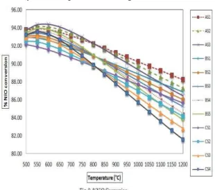
4.2.4. NiO conversion:
It is assumed that the CH4, CO, and H2 are oxidized to CO2 and H2O by means of NiO in the CLC fuel reactor. The oxygen carrier (NiO) gets reduced in the CLC fuel reactor. The NiO conversion slightly decreased with increase in temperature from 500-1200˚C. For e.g. the NiO conversion decreased from 93.75% to 88.23% in case of AS1 while it decreased from 93.21% to 81.57% in case of CS4 as shown in fig. 9.
the 100% carbon conversion was achieved at relatively low temperature for higher GaCR.
4.2.5. 100% carbon conversion in fuel reactor:
It is very important for the CLC process to get 100% carbon conversion in the fuel rector as the unreacted carbon can go to in air reactor and form CO2. The lowest temperature for 100% carbon conversion was found to be 900˚C in case CS1, so this point was found to be the best point for process operation.
Table 2- Carbon Conversion
V.
Conclusion
This theoretical study was done to understand the material balances for process design of direct CLC of rice husk. The study considered the effect of temperature and effect of amount of oxygen carrier in the fuel reactor using steam and CO2 as gasifying agents in steps. It was concluded that rice husk CLC using 3 moles H2O and 0 moles CO2 per mole carbon at 1 bar pressure and 900˚C is the best point to operate the process as hundred percent carbon conversion in the rice husk occurs in the process. The results obtained in this detailed study can be used for
scale up of the process. Further Experimentation is required for the commercialization of the technology.
References
[1] Calin-Cristian Cormos, Letitia Petrescu, “Evaluation of calcium looping as carbon capture option for combustion and gasification power plants”, Energy Procedia, 51, 2014, 154 – 160.
[2] Zhongyi Deng, Rui Xiao, Baosheng Jin, Qilei Song, He Huang, “Multiphase CFD Modeling for a Chemical Looping Combustion Process (Fuel Reactor)”Chem. Eng. Technol., 31(12), (2008), 1754–1766. [3] M. A. Habib, H. M. Badr, S. F. Ahmed, R.
Ben-Mansour, K. Mezghani, S. Imashuku, G. J. la O‟, Y. Shao-Horn, N. D. Mancini, A. Mitsos, P. Kirchen, A. F. Ghoneim, “A review of recent developments in carbon capture utilizing oxy-fuel combustion in conventional and ion transport membrane systems”, Int. J. Energy Res., 35, 2011, 741–764.
[4] MohammadM. Hossain, Hugo I. de Lasa, “Chemical-looping combustion (CLC) for inherent CO2 separations—a review”, Chemical Engineering Science, 63, 2008, 4433 – 4451.
[5] Jung, J. and I.K. Gamwo, „Multiphase CFD based models for chemical looping combustion process: Fuel reactor modeling.” Powder Technology, 183(3), 2008, 401-409.
[6] He Fang, Li Haibin, and Zhao Zengli, “Advancements in Development of Chemical-Looping Combustion: A Review”, International Journal of Chemical Engineering, 2009, (2009).
[7] Henrik Leion, Anders Lyngfelt, Tobias Mattisson, “Solid fuels in chemical-looping combustion using a NiO-based oxygen carrier”, Chemical Engineering Research and Design, 87(11), 2009, 1543-1550. [8] Tobias Mattisson, Marcus Johansson,
Anders Lyngfelt, “The use of NiO as an oxygen carrier in chemical-looping combustion”, Fuel, 85(5–6), 2006, 736-747. [9] M.M. Yazdanpanah, A. Forret, T. Gauthier,
A. Delebarre, “Modeling of CH4 combustion with NiO/NiAl2O4 in a 10 kWth CLC pilot plant”, Applied Energy, 113, 2014, 1933-1944.
[11] Magnus Rydén, Erik Cleverstam, Marcus Johansson, Anders Lyngfelt, Tobias Mattisson, “Fe2O3 on Ce-, Ca-, or Mg-stabilized ZrO2 as oxygen carrier for chemical-looping combustion using NiO as additive”, AIChE Journal, 56(8), 2010, 2211–2220.
[12] T. Mendiara, A. Abad, L. F. de Diego, F. García-Labiano, P. Gayán and J. Adánez, “Biomass combustion in a CLC system using an iron ore as an oxygen carrier.” International Journal of Greenhouse Gas Control, 19, 2013, 322-330.
[13] Rein Kuusik, Andres Trikkel, Anders Lyngfelt, Tobias Mattisson, “High temperature behavior of NiO-based oxygen carriers for Chemical Looping Combustion”, Energy Procedia, 1, 2008, 3885-3892.
[14] J. Adánez, P. Gayán, I. Adánez-Rubio, A. Cuadrat, T. Mendiara, A. Abad, F. García-Labiano, L. F. de Diego, “Use of Chemical-Looping processes for coal combustion with CO2 capture”, Energy Procedia, 37, 2013, 540 – 549.
[15] Aline Lima da Silva, Iduvirges Lourdes Müller, “Towards H2-rich gas production from unmixed steam reforming of methane: Thermodynamic modeling”, Journal of Power Sources, 196, 2011, 8568– 8582. [16] Lin Zhu, Junming Fan, “Thermodynamic
analysis of H2 production from CaO sorption-enhanced methane steam reforming thermally coupled with chemical looping combustion as a novel technology” Int. J. Energy Res, (2014).
[17] Rutuja Bhoje, Ganesh R. Kale, Nitin Labhsetwar, and Sonali Borkhade, “Chemical Looping Combustion of Methane A Technology Development View”, Journal of Energy, 2013, (2013).
[18] X. Wang, B. Jin, W. Zhong, Y. Zhang and M. Song, “Three-dimensional simulation of a coal gas fueled chemical looping combustion process.” International Journal of Greenhouse Gas Control, 5(6), 2011, 1498-1506.
[19] Giddel M.R and. Jivan A.P, “Waste to Wealth, Potential of Rice Husk in India a Literature Review”, International Conference on Cleaner Technologies and Environmental Management PEC, Pondicherry, India, (2007).
[20] XIE Jian-jun, YANG Xue-min, ZHANG Lei, DING Tong-li,SONG Wen-li, LIN Wei-gang, “Emissions of SO2, NO and N2O in a circulating fluidized bed combustor during co-firing coal and biomass”, Journal
of Environmental Sciences, 19, (2007), 109– 116.
[21] MSW learning tools, Copyright © 2001 University of Central Florida.