N. L. Maziero
Universidade de Passo Fundo Faculdade de Engenharia e Arquitetura Campus I, Bairro São José Caixa Postal 611/631 99001-970 Passo Fundo, RS. Brazil [email protected]
J. C. E. Ferreira
Universidade Federal de Santa Catarina Departamento Engenharia Mecânica GRIMA/GRUCON Caixa Postal 476 88040-900 Florianópolis, SC. Brazil [email protected]
F. S. Pacheco
Universidade Federal de Santa Catarina Departamento de Engenharia Elétrica-LINSE Caixa Postal 476 88040-900 Florianópolis, SC. Brazil [email protected]
A Method for the Automatic
Identification of Contacts in
Assemblies of Cylindrical Parts
A significant amount of research has been made on determining the optimum assembly sequence, assembly planning, etc. However, those research works consider that the necessary information for the analysis (e.g. the contacts among the parts in the assembly) is already available, which is not usually the case. This paper describes a method for extracting information within the design, aiming at supporting applications of assembly identification, which is needed for assembly planning. The system determines the surfaces to be machined and the dimensions to receive tighter tolerances, which are important for process and inspection planning. Initially, the group of parts that compose the product is input, and then the procedure for automatic identification of assembled parts begins for the given assembly. The final analysis is done by an expert system that checks the conditions of the assembled parts. The system is applied to cylindrical parts, in a design by features environment.
Keywords: Assembly, computer-aided design, features, expert system, dimensioning
Introduction
Identifying assembled parts, as well as their contact surfaces, is very important in design and manufacturing, since this information is necessary for many decisions, which include: a) determination of the optimum assembly sequence; b) identification of surfaces to be machined; c) determination of the dimensions to receive tolerances and surface roughness; and d) assignment of dimensions as a function of the parts in the assembly. A significant amount of research has been carried out on assembly planning, determining the optimum assembly sequence, etc. (Lim et al., 1995; Zha et al., 1998), but those works consider that the necessary information for the analysis is already available.1
In this paper, a technique for extracting information within the assembly is presented, aiming at supporting applications of assembly planning, determination of surfaces to be machined and dimensions to receive tolerances, which are important for process and inspection planning. The determination of the dimensions to receive tolerances is done while identifying the assembled parts.
The method is applied to cylindrical parts in a feature-based design system. Initially, the group of parts that compose the product is input, and then the procedure for automatic identification of assembled parts begins for the given assembly. The final analysis is done by an expert system that checks the conditions of the assembled parts.
Paper accepted September, 2004. Technical Editor: Atila P. Silva Freire.
Previous Work on Assembly Modeling and Planning
Assembly Modeling
Assembly modeling and manipulation involves structural and spatial relations among individual parts on a much higher level of abstraction than the representation of one single part (Anantha et al., 1996). Therefore, in order to represent an assembly adequately in the computer, the data structure should enable the support to assembly constraints to all parts involved, individual selection of parts in the assembly, choice of the relative position of the parts, and manipulation of the assembly as a whole.
Some data structures for assembly modeling were developed in the past. Two examples of such data structures were the ones implemented by Lee and Gossard (1985) and Ko and Lee (1987). Both have a hierarchical structure, and they use the concept of a link between the elements involved in an assembly.
Another data structure was proposed by Gu and Yan (1995), who represented an assembly through two types of graphs: link graphs and contact relations graph. The link graph provides the connections between parts, but this information is in a generic format, without details like what the relation between the parts is. The contact relations graph describes many types of assembly relations, such as tight fit, sliding fit, key fit and threaded fit. The assembly relations are then classified into two classes, i.e. fits and contacts, where in the end every piece of information is converted into contact relations.
The authors consider that the above data structures have the limitation that they do not use features for part and assembly modeling, and the use of features was recommended by many authors (see for instance Shah, 1992). Features were used for assembly modeling in the system developed by Shah and Tadepalli (1990), which extracts the information about two coupled parts, and allows the choice of fits to be made after the parts are assembled.
The feature-based design modeling approach was also recommended by Mascle et al. (1994), who defined an assembly feature as an interaction between two connected elements (parts or features) by a link that can be mechanical (physical contact) or functional (geometrical or clearance constraints). They proposed the development of a modeler that should be not only geometrical, but also technological, where existing links between the parts should be evaluated.
In that same work, Mascle et al. (1994) proposed that two "visions" should be considered for assembly modeling. One of them adopts the kinematical vision, which is related to the utilization of robots. In this case, the size, tolerances and orientation of the surfaces of the object must be precisely known, and each surface is treated separately. The definition of the assembly characteristics includes: the part geometry (e.g. location and orientation in the Cartesian space), dimensions and directions of assembly; tolerances; relations between the part and the product; identification of similar parts. The other assembly vision utilizes the polyhedral representation of objects and parts; the model includes the following types of information: geometrical information (i.e. form and dimensions of the parts, relative position in the final assembly); information of the parts (e.g. handling, part base, part priorities); final assembly information; topological information (e.g. types of contacts, assembly constraints). Although in the present work these two visions are not contemplated, all of the above data are included in the structure of the system described in this paper.
Features were also used in the system developed by Zha and Du (2002), which is a product data modeling system for concurrent design and assembly planning based on STEP (Standard for the Exchange of Product Model Data - ISO 10103) (ISO, 1992). Their system has a hierarchical structure, and it aims at enabling practical data exchange standards for assembly in computer-integrated systems.
Assembly Planning
Mascle et al. (1994) point out that the use of computers in assembly planning is more difficult than in part manufacture. The main problems are the low level of standards of assembly operations, in contrast with manufacture, where operations such as turning and milling have been known for a long time. The complexity of the assembly planning problem is also mentioned in Gu and Yan (1995), who consider such complexity as the main cause for the slow development of research on automatic assembly of mechanical products by robots compared with the assembly of electronic products.
Bronsvoort and Jansen (1994) and Shah et al. (1994) mentioned that the assembly planning task can be subdivided into different stages, which are:
•Decomposition into subassemblies, which can be determined based either on the functional decomposition or on the connectivity properties that describe the interaction between the parts.
•Generation of possible assembly sequences, which is based on the given subassemblies. However, only some sequences are feasible, since the geometric configuration imposes an order to the assembly sequence.
•Assembly sequence planning, since there are alternative assembly sequences. The objective of a plan is to analyze the different costs involved with respect to tools, transport, and storage, allowing verifying the best conditions for performing the assembly.
•Assembly operation planning, which is responsible for generating the instructions for the equipment in the assembly cell (e.g. robots, conveyors, etc.).
The present work contributes directly to automate the determination of the interactions between the parts in the assembly, thus helping speed up the assembly planning process.
It is generally recognized that the assembly process has low quality, low efficiency and high cost, which are all inter-related. These factors have lead to Design for Assembly ("DFA") (Boothroyd and Dewhurst, 1989), which aims at selecting the most economical production process during the design stage, adapted to the characteristics of the chosen assembly method.
According to Ko and Lee (1987), in order to generate assembly procedures automatically, there are three problems to be considered: a) how to represent an assembly in a computer; b) how to structure the parts hierarchically; c) how to generate assembly procedures from a hierarchical tree of parts. Some works were found in the literature that consider these problems, and one of them was developed by Dini and Santochi (1992), who analyzed subassemblies and assembly sequences based on the mathematical model of the product, obtained through the definition of three matrices: interference, contact and connection. The possible subassemblies are detected automatically when they satisfy some mathematical conditions applied to those matrices. However, the source of those matrices is not revealed, nor how they are obtained so that the analyses can be made.
Another computer-aided assembly system was proposed by De Fazio and Whitney (1987), which questions the user about the assembly, and these questions require geometric reasoning and understanding by the user, which requires the user to have a significant design experience. A system with a higher degree of automation was proposed by Eyada and Ong (1991), which is a CAD system capable of identifying an assembly and specifying the tolerances automatically. The assembly is defined through the recognition of "block" entities that compose the parts in the CAD system. The combinations of parts are identified based on the comparison of lines that compose the different blocks. The system utilizes this information to specify the tolerances automatically.
An expert system called KOMPASS (Weule and Friedman, 1989) utilizes the disassembly sequence for assembly analysis. In that system it is assumed that all the surface connections be known, e.g. the external surfaces of each part that touch other parts, which can become constraints to assembly.
Mazouz et al. (1991) applied artificial intelligence and a knowledge-based system in order to generate an optimum assembly sequence without intervention from the user. They define the parts as external and internal, and assume that contacts occur among the parts in order for the assembly to occur.
Gu and Yan (1995) proposed the utilization of a feature-based CAD system to support the extraction of information from the product in order to perform assembly sequence analysis for robots. However, the algorithms proposed by them assume that the assembly description is available, and so the task becomes to find the best assembly sequence.
Zha and Du (2002), in their feature-based product modeling system for assembly planning using STEP, a knowledge-based expert system was implemented to support the main assembly design and planning process. Those authors mention that the relations among the parts are needed for assembly planning, but they assume that the part relations are already available.
Gottipolu and Ghosh (2003) developed a method for automatically generating assembly sequences from a solid modeler. Based on the assembly model, that method generates two types of matrices indicating the presence or absence of contacts. Those matrices are used by an algorithmic procedure that generates feasible assembly sequences. This method is not feature-based, and the procedure for generating the matrices is not described in that paper.
Different methods were described above for solving the assembly planning problem, and it can be noticed that in those research works the importance of identifying assembled parts for assembly planning decisions to be made. In this paper a computer system that performs automatic identification of assembled parts is described.
Data Representation in the Developed System
In order for a computer software to perform the identification of parts that are assembled in a product, a data structure is necessary, and in this work such a data structure corresponds to a feature-based modeler. This modeler has a hierarchical structure, where a product is composed of an assembly, an assembly can be composed of many subassemblies, a subassembly is composed of the collection of many parts, and each part by one or more features. Each element in this hierarchy has its attributes.
In the present work, it is considered that only one assembly exists, which is composed of many parts, and these are composed of features. The assembly has a name, a list of parts and other attributes. Similarly, the part has a name, a list of features and other attributes.
When analyzing an assembly, it is important to perceive each part in the assembly and each feature in each part. Therefore, it is necessary to define the attributes that will represent each part and each feature involved that have some meaning for assembly. Some of the attributes of a part are: Name, Source and Material. The
Name is given by the user; the Source relates to whether the part is
manufactured by the company itself, by a supplier or whether it is a standard part (e.g. bearings, bolts, etc).
The features are classified into: (i) Basic, which are the cylindrical shaft and the cylindrical hole (it can also be a conical hole), and (ii) Modifiers, which alter the basic features (e.g. fillets, chamfers).
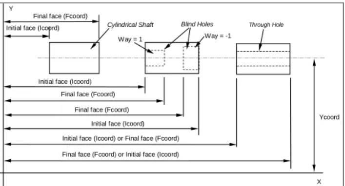
The attributes of a feature cylindrical shaft/hole are:
Name:
Type: cyl_shaft / blind_cyl_hole/ through_cyl_hole Position: internal/external
Direction: axial/radial Way: right/left (1/-1) Centerline: Ycoord Initial Face: Icoord Final Face: Fcoord
Volume: positive/negative (1/-1)
Initial face (Icoord) Final face (Fcoord)
Initial face (Icoord) Final face (Fcoord)
Final face (Fcoord)
Initial face (Icoord) Ycoord
Cylindrical Shaft Blind Holes
Y
X
Through Hole
Initial face (Icoord) or Final face (Fcoord) Final face (Fcoord) or Initial face (Icoord)
Way = 1 Way = -1
Figure 1. Graphical representation of the features cylindrical shaft and hole.
In Fig. 1 the attributes of these features in the absolute coordinate system are represented. For a shaft, the initial face (Icoord) is always on the left-hand side, whereas the final face (Fcoord) is always on the right-hand side. For a blind hole, the initial face (Icoord) is always the start of the hole (its position is chosen by the user with the mouse), and the final face (Fcoord) is the bottom of the hole. For a through hole, the initial face corresponds to the face input by the user, and the final face is opposite to the initial face.
Analysis of the Modeled Product
The decision about having a machined surface and the assignment of a certain tolerance to a dimension, as well as the arrangement of the dimensions to be controlled, is a function of a rigorous analysis of the assembly. Therefore, it is very important the specification of correct attributes to each part and feature, and this is not a result of the analysis of the part alone, but considering the assembly where it will work. In order to decide on the tolerance, surface roughness aspects, and the identification of their surfaces as well as the functional dimensioning, it is essential to have a global vision of the assembly, i.e., the description of how the parts are assembled.
It is necessary a data structure that supports the product representation with its hierarchy. With this information, which is normally analyzed manually by the designer, it is possible to automate these analyses through a computer software.
The first analysis consists of identifying what parts are assembled to one another, as well as the features that have contact between the parts. In other words, which cylindrical surfaces are in contact (i.e. diametrical contacts) as well as the axial contacts that occur. After determining the shaft and the hole that have diametrical contact, it is possible to affirm that these dimensions must be assigned tighter tolerances compared to those surfaces that will not be in contact. If the assembly pair is identified, it is possible to choose interactively, with the help of a program, the type of fit that best suits the pair. The surface finish that must be assigned to these surfaces is determined as a function of the chosen tolerance.
After determining the axial contacts, it is possible to define the tolerances of the axial dimensions, as well as the surface finishes of these surfaces. These surfaces that have axial contact work as references for the axial dimensioning of the parts, from which the assembly conditions of the part can be obtained. As a result, if a surface has a contact, it must be machined, and therefore a good surface finish should be assigned to it.
information can also be utilized for process and inspection planning, and also for operation sequencing.
Characterization of an Assembly
In the present work, during the detailed design phase, the graphical representations are made with nominal dimensions, i.e. neither manufacturing deviations nor functionality problems related to the clearance and interference that should occur between the assembled parts are considered. These problems are solved in another phase, after the design is represented.
When identifying the assembled parts, the system asks the user for information about tolerances and fits, according to the way the assembly pairs are identified. So, when each pair is identified, a module that provides information about the tolerances is activated, and the user selects the one that is most convenient for the coupled pair depending on the application.
Identification of Cylindrical Parts
In order to check whether two parts have diametrical contact, the initial condition is that the nominal dimensions of the hole and of the shaft are the same. Another condition is that the centers of rotation of the parts are coincident. The last condition is that they occupy the same position in space.
In Fig. 2(a) diametrical contact occurs, because: (i) the diameters are the same, (ii) the centers of rotation of both parts are coincident, and (iii) they occupy the same position in space. In Fig. 2(b) the condition of diametrical contact does not occur, since the nominal diameters are different. In Fig. 2(c), although the nominal diameters are the same, and they occupy the same position in space, the centers of rotation are not coincident, and therefore there is no diametrical contact. In Fig. 2(d), the parts do not occupy the same position, and thus there is no diametrical contact, even if the other conditions are satisfied.
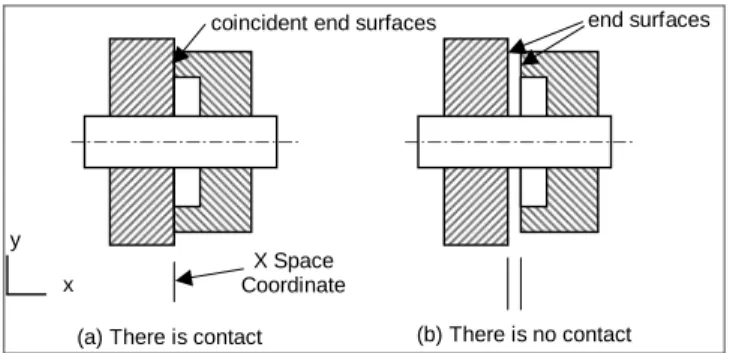
In an assembly of cylindrical parts, usually the axial contact performs the positioning of parts in the assembly. If the position of the end surfaces of two parts is the same, they have axial contact (Fig. 3(a)). In Fig. 3(b) there is no contact because the end surfaces do not coincide.
parts are not centralized
(c)
There is no superposition
(d)
diametrical contact there is no contact
(a) (b)
Figure 2. Conditions for diametrical contact.
The occurrence of two contacts of the same type and at the same time in a part is not adequate for assembly, and an example of this situation is given in Fig. 4(a). However, Fig. 4(b) shows an adequate assembly where there is a contact of each type between the parts. In Fig. 4(c) there are two axial contacts between two parts, resulting in an inadequate assembly. The best solution is represented in Fig. 4(d). The presence of adequate contacts reduces the necessary precision, resulting in easier manufacture, assembly, inspection, etc.
coincident end surfaces coincidentes
x y
X Space Coordinate
end surfaces
(a) There is contact (b) There is no contact
Figure 3. Conditions for axial contact.
An axial contact is defined based on the coordinates that correspond to the plane faces of the features. In Fig. 5 the external axial contacts are represented, and they occur at the plane faces of the features, which in this case are shafts and holes. In Fig. 5(a) it occurs both diametrical contact and axial contact. But in Fig. 5(b), parts 1 and 2 have axial contact despite they do not have diametrical contact, and thus this is another form of assembly. In Fig. 5(c) contact occurs between a face of one internal feature with the face of another external feature.
There are cases where axial contact does not occur between two parts due to the diameter. In Fig. 6(a), diametrical contact occurs between Part0 and Part1, but there is no axial contact. In Fig. 6(b) Part0 and Part1 do not have diametrical contact, and the axial contact does not occur due to the fact that Part0 has an internal diameter greater than the external diameter of Part1. And in Fig. 6(c) there is only diametrical contact between the two parts.
Specification of the Contacts
The identified contacts in an assembly should be represented in a form such that one could know what parts are involved in the assembly, the features in each part and the type of contact that occurs. In order to achieve that, the types of contacts are represented as shown in Fig. 7. In Fig. 8 an example is given with regard to the axial contact, whose attributes are:
•Contact_coordinate: it corresponds to the axial coordinate which is the same for both faces in contact;
•Part_axial_shaft: it is the part that owns the shaft which is in contact with the face of the hole;
•Part_axial_hole: it is the part that owns the hole that is being analyzed;
•Feature_axial_shaft: it corresponds to the shaft that has axial contact with the part that owns the hole;
•Feature_axial_hole: it is the hole whose face is in contact with the shaft in Part_axial_shaft.
With regard to the diametrical contact, its attributes are defined as follows (see Fig. 9):
•Contact_diameter: nominal dimension that is equal to the shaft diameter and hole diameter which are assembled;
•Part_Diameter_Shaft: it is the part that owns the shaft which is in contact with the part that owns the hole;
•Part_Diameter_Hole: it is the part that owns the hole that is in contact with the part that owns the shaft;
•Feature_Diameter_Shaft: it is the shaft feature that is in contact with a hole;
•Feature_Diameter_Hole: it is the hole that is in contact with the shaft;
Two diametrical contacts
One axial contact
(a) contacts in excess (b) adequate contacts Diametrical contact
(c) incorrect contacts (d) adequate contacts Axial contacts in excess
Figure 4. Occurrence of contacts.
Part0
Part1
axial contact: parts 0 and 1
Part0 Part1
Part2
axial contact: parts 0 and 1
axial contact: parts 1 and 2
(a) (b)
axial contact
Part1 Part2
(c)
Figure 5. Axial contact between shafts and holes.
(a) (b) (c)
Part0 Part1 Part0 Part1
Part1 Part0
Figure 6. Situations where axial contact does not occur.
Assembly
Connections
Axial Contact Diametrical Contact
Contact_Coordinate Part_Axial_Shaft Part_Axial_Hole Feature_Axial_Shaft Feature_Axial_Hole
Contact_Diameter Part_Diameter_Shaft Part_Diameter_Hole Feature_Diameter_Shaft Feature_Diameter_Hole Feature_Type
Figure 7. Attributes of the axial and diametrical contacts, which compose the connections class.
Identification of Diametrical Contact
In order to identify the parts and features that are in contact, and to describe the assembly conditions, a procedural algorithm combined with an expert system is applied. This algorithm searches the possible assembly pairs, whereas the expert system verifies the assembly conditions. The flowchart of the procedural algorithm to identify possible diametrical contacts is shown in Fig. 10, where n and m are indexes that refer to two different parts that are to be identified as having diametrical contact (i.e. pair hole/shaft).
Contact_coordinate
Part_Axial_Shaft Part_Axial_Hole
Feature_Axial_Shaft
Feature_Axial_Hole
Figure 8. Definition of the features and parts involved in an axial contact.
Part_Diameter_Shaft Part_Diameter_Hole
Feature_Diameter_Shaft
Feature_Diameter_Hole
Dh
Ds
Dc
Diameter_shaft(Ds) = Diameter_hole(Dh) = Contact_ Diameter (Dc)
Part_Diameter_Shaft Part_Diameter_Hole
Feature_Diameter_Shaft
Feature_Diameter_Hole
Dh
Ds
Dc
Diameter_shaft(Ds) = Diameter_hole(Dh) = Contact_ Diameter (Dc)
Figure 9. Definition of the features and parts that have diametrical contact.
Part(n)
Is there Part (n)? N
Y
Does it have a hole?
N
Y
n=n+1
Is there a hole to the right? Y
Is there a hole to the left?
Y
N
N
Part (m)
Is there Part(m)? N
Y
Part (n) = Part(m)?
N Y
m=m+1
Shaft (k)
Is there Shaft(k)? N
Y
N
Y
Diam/hole = Diam/shaft(k)
? k=k+1 Start
n=0 ; m=0
Expert System verifies the assembly
by the diameter
Is there an assembly by thediameter
? N
Y
Assign values: Diameter Part_Hole Feature_Hole
Part_Shaft Feature_Shaft Type_Feature
1 (fig.11) End
2
Asks information on the tolerances k=0
The process of identification of assembled parts in an assembly begins with the search for the first part in the assembly, and if there is no part (Part(n)), the algorithm ends. If there is a part, the next step is to verify whether the part has a hole. If there is no hole, the algorithm searches the next part in the assembly (Part(n+1)). If there is a hole, it is checked whether the hole is to the right or to the left. Whatever is the way, the algorithm searches the first part in the assembly (Part(m)). If the assembly does not have a part of index m, the algorithm returns to the starting point and gets the part
Part(n+1). If there is no other part, the algorithm ends.
If part Part(m) exists, it is checked whether both parts (n and m) are the same, i.e., if they have the same name. If that is the case, the next part (Part(m+1)) is obtained, it is checked whether the first feature in this part (i.e. a shaft) has its nominal diameter equal to the diameter of the hole. If they are different, the algorithm searches the next shaft, and repeats the operation until it finds a shaft with nominal diameter equal to the hole diameter. If no shaft is found, the algorithm starts to traverse the next part.
If there is a shaft and a hole with the same nominal diameters, the information about them is sent to the expert system, which verifies the occurrence of assembly or not. If there is no assembly, the next shaft in the part is searched. If the expert system confirms the assembly, the information that characterizes the assembly by the diametrical contact is stored in the data structure.
Identification of the Axial Contact
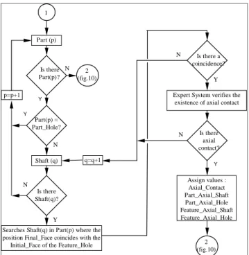
If the assembled pair hole/shaft is accepted (diametrical contact, exit 1 in the flowchart in Fig. 10), it is verified whether there are axial contacts between the hole in the part and the other parts in the assembly; also, the axial contacts between the features are verified (Fig. 11). This information is stored in the attributes described in the
connections class (Fig. 7).
2 (fig.10)
2 (fig.10) 1
Part (p)
Is there Part(p)?
Part(p) = Part_Hole? Y p=p+1
N
Searches Shaft(q) in Part(p) where the position Final_Face coincides with the Initial_Face of the Feature_Hole
Is there a coincidence? N
q=q+1
Y
Expert System verifies the existence of axial contact
N
Y
Assign values : Axial_Contact Part_Axial_Shaft Part_Axial_Hole Feature_Axial_Shaft Feature_Axial_Hole N
Y
Is there Shaft(q)?
Y N
Shaft (q)
Is there axial contact?
Figure 11. Flowchart of assembly analysis - identifying the axial contact.
After the parts and features involved in the description of diametrical contact are identified, the identification of the axial contact starts with the feature Part_Hole and Feature_Hole that have diametrical contact. The assembly structure is traversed in order to
find a shaft in a part whose initial face (Icoord) or final face (Fcoord) coincides with the initial face of Feature_Hole.
If there is a shaft in these conditions, the expert system performs the analysis and returns a conclusion. If the conditions satisfy the assembly and the axial contact, the information is stored in the data structure as attributes of the subassembly, in the connections class. If the conditions do not occur, the next shaft in the part chosen for analysis is searched, or the next part. In the end the system returns to node “2” in the flowchart in Fig. 10, and continues the search in the assembly.
Implementation of the Expert System
The implementation of the expert system consists of modeling situations in the form of rules. Each situation should be described considering both the conditions that cause its approval and the conditions that disapprove them.
The shell for the development of expert systems CLIPS was used. It allows the description in the form of classes, and it provides the inheritance mechanism, which permits to simplify significantly the definitions.
Implementation of the Knowledge Base for Assembly
The procedural algorithm verifies the conditions that characterize the assembly, whereas the expert system performs a more detailed analysis, which can be of two types, i.e. diametrical and axial contacts. They correspond to two independent modules within the same knowledge base, and they are activated through the algorithm represented in figs. 10 and 11.
Rules for Identifying Diametrical Contacts
The information about the parts and features is provided to the expert system through a communication interface that converts the data recorded in the product model into the format read by the expert system. The information in feature format in the product model is independent of the CAD system database, which is utilized here as a graphical tool.
In order to identify a diametrical contact, it is necessary information on: a) the part that owns the hole, and about the hole itself; b) the part that owns the shaft, and about the shaft itself. The attributes described in the definition of the features are utilized for writing up the rules.
The system in its current implementation has 80 rules in its knowledge base, and one example of rule is presented below. Note that in the rules the letter "H" refers to a hole, and the letter "S" refers to a shaft.
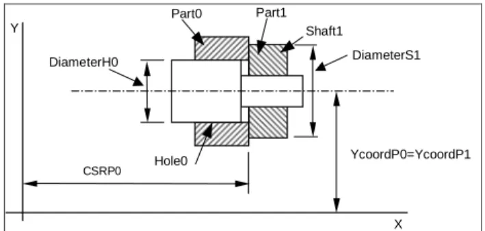
Rule 1:
Assembly occurs if the shaft has Fcoord outside the hole and IcoordS=IcoordH (Fig. 12)
IF (YcoordH = YcoordS) and (Type=through_cylindrical_hole) and (DiameterH = DiameterS) and (Way = 1)
and (IcoordH = IcoordS) and (FcoordH < FcoordS)
and ((FcoordH - IcoordH) ≥ DiameterH/2)
CSRP0
Part0 Part1
X Y
DiameterS1 DiameterH0
Hole0
Shaft1
YcoordP0=YcoordP1
Figure 12. Graphical representation of Rule 1 of diametrical contact.
As initial condition, the centers of rotation of the hole and the shaft must coincide, and the feature is a through cylindrical hole; another condition is that the hole and the shaft must have the same nominal diameter; and the hole must have its way to the right.
The axial positioning condition between the hole and the shaft is analyzed with regard to the positioning of their respective initial and final faces. The initial faces of the hole and shaft should coincide, and the final face of the hole does not coincide with the final face of the shaft, and it must be located closer to the initial face of the hole. Finally, the supporting dimension between the hole and the shaft must be equal to half of the hole diameter.
If this rule is triggered, the expert system sends a message confirming that the coupled pair of features is an assembly, and at the same time this message activates a module for selecting interactively the tolerances for that assembly pair.
Rules for Identifying Axial Contacts
For the occurrence of axial contact, it is necessary that the position coordinates (Icoord and Fcoord) of two faces of features in different parts have the same nominal value. The verification of axial contact is done only for the features that have diametrical contact, and the assembly condition accepted (see figs. 10 and 11). Some rules are presented below.
Rule 1:
Axial contact between a part with a hole to the right and any other part (Fig. 13)
IF (YcoordP0 = YcoordP1) and (CSRP0 = FcoordS0) and (WayH1 = 1) and (DiameterH0 < DiameterS1) and (FcoordS0 = IcoordH1)
THEN Flag = 0 (there is axial contact between the parts)
IcoordH=IcoordS
FcoordH
FcoordS
YcoordH=YcoordS
X Y
Support length
Figure 13. Graphical representation of Rule 1 of axial contact.
This rule analyzes two parts that have axial contact only, and the diametrical contact occurs through a third part. The first condition is that the center of rotation of the involved parts must coincide. Also,
the shaft in Part0 is the last on the right-hand side of the part (CSRP0 = FcoordS0).
The hole is towards the right, and in order to occur axial contact the hole diameter in Part0 must be smaller than the shaft diameter in Part1, otherwise Part0 and Part1 would have only coincidence of positioning. In order to confirm the axial contact, the final face of the shaft in Part0 must coincide with the initial face of the hole in Part1.
Rule 2:
There is no axial contact between a part with a hole to the right with any other part (Fig. 14)
IF (YcoordP0 = YcoordP1) and (CSRP0 = FcoordS0) and (WayH1 = 1) and (DiameterH0 > DiameterS1) and (FcoordS0 = IcoordH1)
THEN Flag = 1 (There is no axial contact between the parts)
X
Y Part0 Part1
Shaft1 Hole0
YcoordP0=YcoordP1 DiameterS1
DiameterH0
CSRP0
Figure 14. Graphical representation of Rule 2 of axial contact.
This rule is similar to the previous one, and the difference is that the diameter of the hole in Part0 is greater than the shaft in Part1, which is not an axial contact between the faces of both parts involved.
Application Example
An assembly of cylindrical parts is presented in Fig. 15. The assembly is composed of a rear housing that is closed by a front housing, and a stepped_shaft is located inside, over which a rotor and a bushing are assembled. The shaft is supported by the holes located in the rear housing and the front housing.
rear housing
stepped_shaft
front housing
rotor bushing
Figure 15. Assembly based on Dini and Santocchi (1992).
CLSH0
CLHL0 CLHL1
CLSH0 CLSH1
CLHL0
(a) features that compose the rear housing
(b) features that compose the front housing
Figure 16. Description of the features that compose the rear housing and the front housing.
In Fig. 17 the parts stepped_shaft, rotor and bushing are represented, with their respective features indicated. The attributes of those parts are presented in Table 2.
CLSH0
CLSH1 CLSH2
CLSH3 CLSH4
CLSH5
(a) stepped_shaft (b) rotor ( c) bushing
CLSH0
CLHL0
CLSH0
CLHL0
Figure 17. Indication of the features that compose the parts stepped_shaft, rotor and bushing.
The process of assembly identification begins with the rear housing, which was the first part to be created through the feature modeler. Since the rear housing has a hole (CLHL0), another part that has a shaft with the same diameter of the hole (= 70, according to Table 1) is searched. The next part is the front housing, which has a shaft (CLSH1) with diameter equal to 70 (see Table 1).
After the algorithm identifies the shaft, the expert system receives the data referring to the involved features. The rule below sets the conditions for assembly between the above parts:
IF (YcoordH = YcoordS) and (Type = blind_cylindrical_hole) and (DiameterH = DiameterS) and (WayH = -1)
and (IcoordH = FcoordS) and (IcoordH < FcoordS) THEN Flag = 0 (assembly occurs)
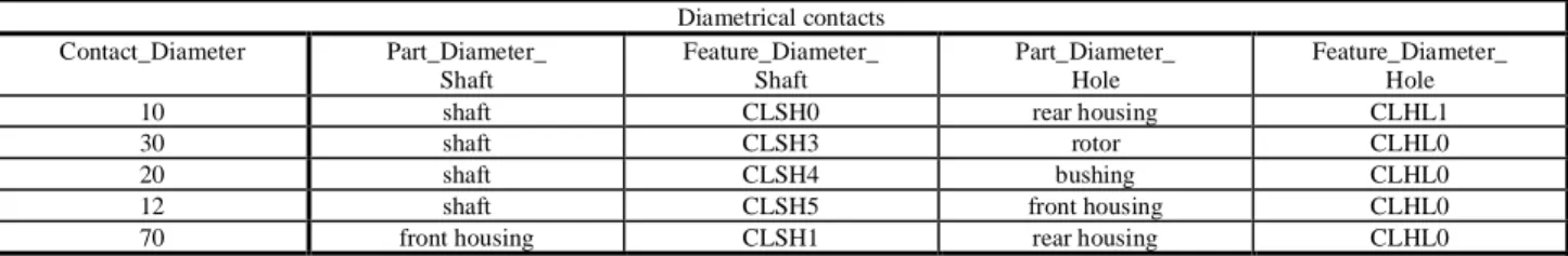
All the conditions in the LHS of this rule are satisfied (see Table 1), and therefore this rule is triggered. Notice that the last two conditions guarantee that CLSH1 in the front housing is inside CLHL0 in the rear housing. So, this rule assures that there is an assembly with diametrical contact between the rear housing and the front housing. These data are sent as attributes to the connections class. The diameters that have diametrical contact are shown in Fig. 18, and their characteristics are shown in Table 3 in the form of attributes that belong to the connections class.
Figure 18. Diametrical and axial contacts among the parts in the assembly example.
Table 1. Attributes of the features in parts rear housing and front housing.
Features in part rear housing Features in part front housing
Name CLSH0 CLHL0 CLHL1 CLSH0 CLSH1 CLHL1
Type cylindrical_shaft blind_ cylindrical_hole
Through cylindrical_ hole
cylindrical_shaft cylindrical_shaft through_ cylindrical_hole
Position external internal internal external external internal
Direction axial axial axial axial axial axial
Way 1 -1 -1 1 -1 1
Ycoord 100 100 100 100 100 100
Icoord 100 185 112 185 185 177
Fcoord 185 112 100 192 177 192
Leng/Depth 85 73 12 7 8 15
Diameter 90 70 10 90 70 12
Volume 1 -1 -1 1 1 -1
Table 2. Attributes of the features in parts stepped_shaft, rotor and bushing.
Features in stepped_shaft Features in rotor Features in bushing
Name CLSH0 CLSH1 CLSH2 CLSH3 CLSH4 CLSH5 CLSH0 CLHL0 CLSH0 CLHL0
Type cyl_shaft cyl_shaft cyl_shaft cyl_shaft cyl_shaft cyl_shaft cyl_shaft through_cy l_hole
cyl_shaft through_cy l_hole Position external external external external external external external internal external internal
Direction axial axial axial axial axial axial axial axial axial axial
Way -1 1 1 1 1 1 1 1 1 1
Ycoord 100 100 100 100 100 100 100 100 100 100
Icoord 112 112 115 122 152 177 122 122 154 154
Fcoord 100 115 122 152 177 227 154 154 174 174
Leng/Depth 10 3 7 30 25 50 32 32 20 20
Diameter 10 22 40 30 20 12 60 30 40 20
Table 3. Diametrical contacts and the attributes in the class connections.
Diametrical contacts Contact_Diameter Part_Diameter_
Shaft
Feature_Diameter_ Shaft
Part_Diameter_ Hole
Feature_Diameter_ Hole
10 shaft CLSH0 rear housing CLHL1
30 shaft CLSH3 rotor CLHL0
20 shaft CLSH4 bushing CLHL0
12 shaft CLSH5 front housing CLHL0
70 front housing CLSH1 rear housing CLHL0
After making sure that there is diametrical contact, it is verified the presence of axial contact that may occur between the cylindrical hole CLHL1 in the rear housing with a shaft in another part. Therefore, a search for a new part in the assembly that owns a shaft whose Icoord or Fcoord attributes coincide with the Icoord attribute of hole CLHL0 (see Table 1) is started.
In this case, there are two shafts in the front housing (CLSH0 and CLSH1), that may have axial contact with hole CLHL0 in the rear housing, and shaft CLSH0 has Fcoord=185, while shaft CLSH1 has Icoord=185. However, only shaft CLSH0 in the front housing has a diameter greater than the diameter of the hole CLHL0, and so it allows the contact between the initial surface of the hole and initial surface of the shaft. The rule below sets the conditions for verifying this axial contact (index “0” corresponds to the features in the front housing, and index “1” to the features in the rear housing):
IF (YcoordP0 = YcoordP1) and (IcoordS0 <> CSLP0) and (Type = blind_cylindrical_hole) and (WayH = -1) and (IcoordH1 = IcoordS0) and (DiameterH1 < DiameterS0) THEN Flag = 0 (assembly occurs)
The condition (IcoordS0 < > CSLP0) assures that the initial face of the shaft in the front housing does not coincide with the leftmost face of the part. The condition (IcoordH1 = IcoordS0) assures that the shaft CLSH1 in the front housing is inside the hole CLHL0 in the rear housing. The condition (DiameterH1 < DiameterS0) means that the diameter of the hole CLHL0 in the rear housing must be smaller than the diameter of the shaft CLSH1 in the front housing, which guarantees the support between the two end surfaces. This can be seen in Fig. 18 in position=185, and in Table 4, where the conditions of axial contact in the connections class are shown.
Since the rear housing has another hole (diameter = 10), this is the next hole to be analyzed. The system then searches a shaft that has an equal diameter, which corresponds to shaft CLSH0 in the part stepped_shaft (Fig. 17). The triggered rule is as follows:
IF (YcoordH = YcoordS) and (Type = hrough_cylindrical_hole) and (DiameterH = DiameterS) and (WayH = -1)
and (IcoordH = FcoordS) and (FcoordH < IcoordS) THEN Flag = 0 (assembly occurs)
The result of the analysis can be seen in Table 3 in the line Contact_diameter = 10. The procedure to identify the axial contact is the same as was described previously, and it corresponds to the contact between the bottom of the hole CLHL0 in the rear housing and the shaft CLSH1 in the stepped_shaft.
Since there are no more holes in the rear housing, the next part to be analyzed is the front housing, which has a through cylindrical hole with diameter equal to 12 (i.e. CLHL1, see Table 1), which has diametrical contact with the cylindrical shaft CLSH5 (see Table 2) in the stepped_shaft. This situation is confirmed by the following rule:
IF (YcoordH = YcoordS) and (Type = hrough_cylindrical_hole) and (DiameterH = DiameterS) and (WayH = 1)
and (IcoordH = FcoordS) and (FcoordH < FcoordS) THEN Flag = 0 (assembly occurs)
The axial contact is made at position=177 (see Fig. 18), which is confirmed by the rule below, and also from the indications in Tables 1 and 2 (index “0” corresponds to the stepped_shaft, and the index “1” to the front housing).
IF (YcoordP0 = YcoordP1) and (FcoordS0 <> CSRP0) and (WayH = 1) and (IcoordH1 = FcoordS0)
and (DiameterH1 < DiameterS0) THEN Flag = 0 (assembly occurs)
The condition (FcoordS0 < > CSRP0) means that the final face of the shaft must not coincide with the right-end of the part.
The next part that has a cylindrical hole is the rotor, in which the diametrical contact between hole CLHL0 and shaft CLSH3 in the stepped_shaft (diameter = 30) was identified (see Fig. 18). In this case the length of the shaft CLSH3 in the stepped_shaft is smaller than the depth of the hole CLHL0 in the rotor. The next rule describes these conditions, and the result is found in Table 3 in the line Contact_diameter = 30.
IF (YcoordH = YcoordS) and (Type = hrough_cylindrical_hole) and (DiameterH = DiameterS) and (WayH = 1)
and (IcoordH = IcoordS) and (FcoordH > FcoordS) THEN Flag = 0 (assembly occurs)
This rule confirms that axial contact occurs between shaft CLSH2 in the stepped_shaft and the hole CLHL0 in the front housing. The description of this axial contact is shown in Table 4 in the line Axial_contact=122.
Since the rotor also has only one hole, the algorithm searches for the next part, which is the bushing, and it has one hole (CLHL0) with diameter=20 (Fig. 18). The algorithm also finds a shaft CLSH4 in the part stepped_shaft, and the assembly is confirmed by the following rule:
IF (YcoordH = YcoordS) and (Type = hrough_cylindrical_hole) and (DiameterH = DiameterS) and ((WayH = 1) or (WayH -1)) and (IcoordH > IcoordS) and (FcoordH < FcoordS)
THEN Flag = 0 (assembly occurs)
The axial contact is given by rule 1 described in section 4.3. The information that results from this analysis is shown in Table 3 in the line corresponding to Contact_diameter = 20, and in Table 4 in the line Contact_coordinate = 154.
Assignment of Dimensions and Tolerances
Since it is known which parts have diametrical contact, it is possible to access this information in the connections class, and through the recommended tolerances to define automatically what roughness to assign to the surface.
Since in the present work the surfaces with axial contact are also known, it is possible to define what dimensions must be assigned special tolerances. The identification of the reference surfaces in each part corresponds to verifying in the connections class what parts and features have the same contact surface, which can be used for nominal dimensioning, and then to decide the tolerances to be applied.
In Fig. 19 the stepped_shaft is presented, on which the surfaces that have axial contact are indicated. In the figure it is also shown the dimensions that must be controlled rigorously (A, B and C), where “C” is the depth of the hole CLHL0 in the rear housing. In this way, each part has one or more surfaces with axial contact recorded in Table 5, which is a result of Table 4. Such surfaces are references for the dimensioning of each part.
Table 4. Axial contacts.
Axial Contacts Contact_
coordinate
Part_Axial _Shaft
Feature_Axial _Shaft
Part_Axial _Hole
Feature_Axial_ Hole
112 shaft CLSH1 rear
housing
CLHL1
122 shaft CLSH2 rotor CLHL0
154 bushing CLSH0 rotor CLHL0
177 shaft CLSH4 front
housing
CLHL0
185 front housing
CLSH1 rear
housing
CLHL0
stepped_shaft housings
Figure 19. Surfaces with axial contact and dimensions to be controlled.
Table 5. References for dimensioning.
References of contact for dimensioning
Part Name Reference 1 Reference 2 Reference 3 Reference 4
shaft 112 122 177 ---
rear housing 112 185 --- ---
bushing 154 --- --- ---
rotor 122 154 --- ---
front housing
177 185 --- ---
Software and Hardware Utilized
The algorithm was implemented in C++, running under AutoCAD for Windows on a Pentium PC. The features are represented in a data structure that is independent of the CAD database. In order to do that, an element that links the data structure to the CAD database was used, which permits the correspondence between the graphical and technological data about the features and the graphical entities of the CAD system.
As mentioned previously, the CLIPS expert system shell was used, which allows object-oriented programming, besides providing an easy communication with the independent data structure.
The system’s communication is done in the following way: ADS (Autodesk Development System, which is Autodesk’s proprietary programming language) ↔ C++ (used for part and feature management, aiming at sending assembly candidates to the expert system) ↔ CLIPS (used for assembly verification). When the user runs the system, he/she is in the AutoCAD environment; but depending on the choice made in the main menu, actually C++ and CLIPS will be running transparently.
Conclusions
In this paper a method to identify assembled parts automatically in a feature-based design environment was described. This method was implemented in order to reduce the time to perform the assembly design process using the computer.
The utilization of features for assembly modeling was important, because through the features it was possible to identify the information necessary to perform assembly analysis. The implemented data structure allowed the representation of assemblies, parts and features, which helped identify the diametrical and axial contacts among the features, consequently enabling decisions to be made on the relations between the parts.
The information extracted from the product about the assembly must be stored in a format that can be interpreted, and in the present work it corresponds to the connections class, which is an attribute of the assembly. The information in the connections class is used to generate a list describing the links between the assembled parts, the involved features and the type of link (i.e. diametrical or axial). This list was successfully used to generate the functional dimensions for the parts in the assembly, and this procedure is described in (Maziero et al., 2001). Also, this list helped identify the parts that need to be assigned tighter tolerances due to contacts that occur between them.
Although the developed system allows the automatic identification of the assembly relations among the parts based on features, in the present implementation modifications to a part cannot be made after the part is positioned in the assembly, i.e. such modifications do not propagate to the other parts in the assembly. The authors intend to implement a solution to this problem in the future, which can be facilitated because the contacts among the parts are already available in the system.
One of the difficulties in the development was the use of a graphical representation of the model in 2D, but the authors consider that it was sufficient for validating the applied concepts.
The utilization of an expert system gives flexibility to the developed software, since it is possible to alter the knowledge base without modifying the main system. However, careful attention should be given when defining the parameters that represent the physical situation of assembly, which must be included in the rules. The authors consider that the developed knowledge base encompasses the types of assemblies that can occur with the features described in the system.
When the dimensions, tolerances, fits and their relations among the parts and features are known, this information can be sent to a process planning system, an inspection planning system, or a program that analyzes the assembly sequence performed by robots.
The system so far considers only simple features, but it is intended to extend it to other types of features, such as threaded parts.
parts. However, the authors have not yet contemplated the applicability of this approach to prismatic parts, which is considered a subject of further investigation.
References
Anantha, R., Kramer G.A. and Crawford, R.H., 1996, "Assembly Modelling by Geometric Constraint Satisfaction", Computer-Aided Design, 28(9), 707-722.
Boothroyd, G. and Dewhurst, P., 1989, “Product Design for Assembly”, Boothroyd Dewhurst Inc.
Bronsvoort, W.F. and Jansen, F.W., 1994, "Multiview Feature Modelling for Design and Assembly", in: Shah, J.J., Mäntylä, M. and Nau, D.S., eds., Advances in Feature Based Manufacturing, (Elsevier Science), 313-330.
Chen, K.Z., Feng, X.A. and Ding, L., 2002, “Intelligent Approaches for Generating Assembly Drawings from 3-D Computer Models of Mechanical Products”, Computer-Aided Design, 34 (5), 347-355.
De Fazio, T.L. and Whitney, D.E., 1987, "Simplified Generation of All Mechanical Assembly Sequences", IEEE Journal of Robotics and Automation, RA-3(6), 640-658.
De Lit, P., Latinne, P., Rekiek B. and Delchambre, A., 2001, "Assembly Planning With an Ordering Genetic Algorithm”, International Journal of ProductionResearch, 39(16), 3623-3640.
Dini, G. and Santochi, M., 1992, "Automated Sequencing and Subassembly Detection in Assembly Planning", Annals of the CIRP, 41 (1), 1-4.
Eyada, O.E. and Ong, J.B., 1991, "An Assembly Recognition Algorithm for Automatic Tolerancing", Transactions of NAMRI/SME, 309-314.
Gottipolu, R.B. and Ghosh, K., 2003, “A Simplified and Efficient Representation for Evaluation and Selection of Assembly Sequences”, Computers in Industry, 50 (3), 251-264.
Gu, P. and Yan, X., 1995, "CAD-directed Automatic Assembly Sequence Planning", International Journal of Production Research, 33 (11), 3069-3100.
ISO 10303, 1992, “STEP Part 203, Application Protocol: Configuration Controlled Design”.
Ko, H. and Lee, K., 1987, "Automatic Assembling Procedure Generation from Mating Conditions", Computer-Aided Design, 19 (1), 3-10.
Lee, K. and Gossard, D.C., 1985, "A Hierarchical Data Structure for Representing Assemblies: Part 1", Computer-Aided Design, 17 (1), 15-19.
Lim, S.S., Lee, I.B.H., Lim, L.E.N. and Ngoi, B.K.A., 1995, “Computer-Aided Concurrent Design of Product and Assembly Processes: a Literature Review”, Journal of Design and Manufacturing, 5, 67-88.
Mascle, C., Dupinet, E. and Maranzana, R., 1994, "Feature Modeling in Assembly Planning", in: Proceedings of the IFIP International Conference of Feature-Modeling and Recognition in Advanced CAD/CAM Systems, 2, 605-627.
Maziero, N. L. and Ferreira, J.C.E., 2001, “Automatic Dimensioning of Cylindrical Parts in an Intelligent Feature-Based Design System”, in International IFIP Conference on Feature Modeling and Advanced Design-For-The-Life-Cycle Systems - FEATS 2001, Valenciennes, France
Mazouz, A. K., Souilah, A. and Talbi, M., 1991, "Design of an Expert System for Generating Optimal Assembly Sequences", Computer-Aided Engineering Journal, 255-259.
Ngoi, B.K.A. and Ong, C.T., 1996, "Optimum Assembly Using a Component Dimensioning Method", Advanced Manufacturing Technology, 11, 172-178.
Shah, J.J. and Tadepalli, R., 1990, "Feature Based Assembly Modeling, Computers in Engineering", 1, 281-287.
Shah, J.J., 1992, “The Design of Design Environments”, Computers in Engineering, 1, 253-260.
Shah, J.J., Mäntylä, M. and Nau, D., 1994, "Introduction to Feature Based Manufacturing", in: Shah, J.J., Mäntylä, M. and Nau, D.S., eds., Advances in Feature Based Manufacturing, (Elsevier Science), 1-11.
Weule, H. and Friedman, T., 1989, "Computer-Aided Product Analysis in Assembly-Planning", Annals of the CIRP, 38 (1), 1-4.
Zha, X.F., Lim, S.Y.E. and Fok, S.C., 1998, “Integrated Intelligent Design and Assembly Planning: A Survey”, International Journal of Advanced Manufacturing Technology, 14, 664-685.